I thought I’d look into reading data from an EEPROM that is I2C capable from a PCB, the PCB is from a KVM which is a device that allows you to use your keyboard, video (monitor) and mouse on different PCs without switching out the cables.
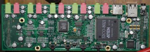
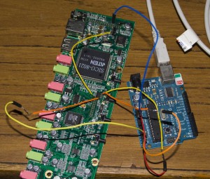
Below is the PCB and the EEPROM which we’ll be looking at.
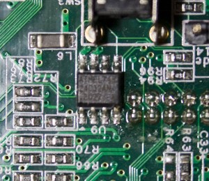
If you can make it out it’s a Atmel 24C32A, a 32Kbit EEPROM, datasheet here: atmel 24c32a
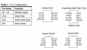
First things first, we need to check the datasheet to see which pins are for what and then verify those findings.
We are looking at the 8-lead SOIC, so A0 on the picture taken above would be the lower left, GND then lower right, VCC the top left and SDA the top right. Now we use our multimeter to find the GND, we do this by touching one probe to the pin we suspect is GND and then one to the power supply input GND or any other nearby devices that we know would be GND, like a USB header plate; we can now do this for the VCC however depending on the circuit your multimeter might not show 0 ohms or beep.
Now we probe A0, A1 and A2 to find what they are; turns out that they are connected to GND so the address will be 1010000 (shown on the datasheet page 11).
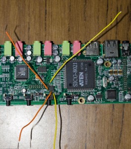
Time to solder some wires to it, you don’t need to much of the wire sticking out, just the bare minimum and only touch the EEPROM pins for just a second no more.
It’s time to connect it to the Arduino and program the Arduino.
I found this guide to step me through accessing an EEPROM via I2C: http://10kohms.com/arduino-external-eeprom-24lc256 (edit: this website is down but I have a copy here: Expanding-the-Arduino-storage-with-an-external-I2C-EEPROM-chip-24LC256-10kohms)
Here is the code I used, basically it just asks the EEPROM from address 0 to 4096 and sends it to serial monitor application in the Arduino program.
#include

#define disk1 0x50

void setup(void){
 Serial.begin(9600);
 Wire.begin();
 unsigned int address = 0;
 for (address = 0; address < 4096; address++) {  Serial.print(address);  Serial.print("\t");  Serial.print(readEEPROM(disk1, address), DEC);  Serial.println();  } } void loop(){ } byte readEEPROM(int deviceaddress, unsigned int eeaddress ) {  byte rdata = 0xFF;  Wire.beginTransmission(deviceaddress);  Wire.send((int)(eeaddress >> 8));   // MSB
 Wire.send((int)(eeaddress & 0xFF)); // LSB
 Wire.endTransmission();

 Wire.requestFrom(deviceaddress,1);

 if (Wire.available()) rdata = Wire.receive();
 return rdata;
}
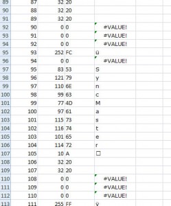
After a few seconds we have all the data which I copy across to an Excel spreadsheet found here: eeprom data XLS or eeprom data CSV. I have only included the first 360 addresses because the other addresses were just full of 255’s. Now 8 bit EEPROMs store a number from 0 to 255 so I’ve got another column in the spreadsheet to convert the number to hex and another column to convert it to ASCII.
If you scroll down a bit in the eeprom data spreadsheet you’ll see what looks like garbage but on the address 95 we have some real text, it says Syncmaster which is a model of a Samsung monitor that was connected to it, I was excited to see that! 😛
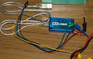
Just for fun I thought I’d attach my newly received Scanalogic 2 Pro to the SDA/SDL and see the data myself.
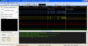
I’ve got it set to 500KHz, trigged as logic change and then reset the Arduino, only have around 500ms of capture it as shown below. Download the save here: atmel 24c32a data via i2c on kvm pcb
Now we zoom right in and we can see the first request to the EEPROM for data, W>>80 in Hex is W>>0x50 (our EEPROM address), the first Write: 0 I believe is telling the EEPROM that we want to read, the second Write: 0 is the address and the R<<80 is the reply from the EEPROM (0x50 hex) and the data back which is 0.
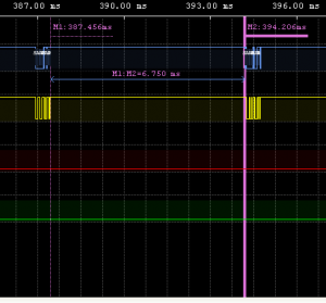
Seems like there is quite a delay between each read request, I’ve found it to be 6.7ms, could this be improved? I think it should be possible, the datasheet does say that the “Time the bus must be free before a new transmission can start” is 1.2us. I think it could be the serial printing that is slowing everything down.
And that’s the end of my playing around with this EEPROM, it was quite exciting to actually see it all work. I’m thinking next I could perhaps grab the data from the Logitech LX310 receiver from my last teardown and then use the Scanalogic to capture data from it whilst it’s actually functioning to see what if anything changes in the EEPROM.


http://www.insidegadgets.com/wp-content/uploads/2010/12/Expanding-the-Arduino-storage-with-an-external-I%C2%B2C-EEPROM-chip-24LC256-10kohms_files.zip
When I d/l this I get the files but not the html file to go with them?
Oops my mistake, here it is with the HTML file: http://www.insidegadgets.com/wp-content/uploads/2010/12/Expanding-the-Arduino-storage-with-an-external-I2C-EEPROM-chip-24LC256-10kohms.zip
don’t know where to ask. finally, i made a small speedometer using attiny2313 and a hall sensor. it sends data to uart port so that I can read it on my ipod.
now i have to save odometer data to the internal EEPROM. What I want to do is to save it on power loss. The idea is to use a Schottkie diode and an electrolytic capacitor between the VCC pin of the µc and the 1117-33, and to watch the power source directly on the other pin of the µc and use the BOD. The data to be saved is long int, which is 4 bytes. To save each byte the microcontroller needs 3.4ms, which renders to at least 13.6ms (under normal voltage, but i’ll be sourcing the device from 3.3V – as I don’t want to burn my ipod). Do you have any idea of what’s the minimum voltage drop out of the diodes (which one to use), and how long does it take for a capacitor to discharge from 3.3v to 2.8v with the typical consumtion of the microcontroller (not sure but the datasheet says it’s 230µA)
Hi, good to hear that you’ve progressed with your project!
The 230uA current at 1MHz is for when it’s running at 1.8V, for 3.3V it’s about 500uA. When you write to the EEPROM the current draw should increase although I don’t know how much by, it could be 1mA or more.
For the diode you want a schottky diode as they have a very low drop voltage, try the part BAT42. If you check that part’s PDF, it will show you the voltage drop vs the current being used – for 3mA it seems to be 300mV drop (but you should always test this out).
For the capacitor, you would want at least 150uF but I think 330uF would be better suited. You can simulate the discharge of the capacitor using Circuit Simulator, 330uF with a 1mA load seems to last 150ms.
my supplier doesn’t have BAT42. Trying to understand if BAT54C would suit my needs.
If the current you will consume is 1mA there will be a 300mV drop on the BAT54C.
VCC -> 1117-33 (3.3V) -> Schottky -> Capacitor -> AVR
Is this what you want to achieve? And you would measure the 1117-33 output with the ADC? What voltage do you or would you like to run the AVR and other components at?
argh, after a while I decided to continue with atmega328, turn to LM7805, and use voltage divider to 3.3 for my ipod’s uart.
1. not sure if I can both source µc and recharge my iPod (0.5A) from the same LM7805, or should I better have two separate circuits for these purposes?
2. that’s the ultimate degree of stupidity, but I can’t find out neither in datasheets nor in the internet how to use BOD with an extra capacitor and schottky to save couple of bytes on power loss, although it seemed I saw it in the datasheet…
all clear. just understood, it’s not a BOD, it’s external interrupt (probably, int1) on falling edge 😉
hope, a large capacitor after the voltage regulator won’t affect the accuracy of ADCs
1. Yes you can the LM7805 can provide up to 1A, just make sure you are using a decent heatsink on it.
E.g 12V in, 5V out with 0.5A output means the LM7805 is dissipating 3.5W ((12 – 5) *0.5). Anything about 1W for a TO-220 you would want a heatsink on.
it’s not about LM7805, it’s about the quality of vcc for µc (with my eeprom writes on power loss, various adc’s, etc. This could bring some troubles, when I have a 0.5A load turning on and off next to a µc, drawing next to nothing. however, i’m not sure if it is nice to connect the grounds of the two LM7805.
besides, when the engine is on, the Vin will be closer to 14-15, which means, T0-220 will have to dissipate even more heat.
I just ported the code from tiny2313 to mega328. tested okay, from the very first attempt, with ADC 😉
Right now I’m gonna draw the circuit in Eagle and try to layout the board (for higher adc accuracy it’s not that easy). haven’t decided yet which connectors to use and what sort of case it will be.
Ah I see, I suspect that switching 0.5A on and off won’t be good for the ADC (at least).
look, i need advice on the cable to connect my device to my ipod. I just ordered 30-pin connectors to ipod and I need a cable to transfer at least stereo line out (3 wires), full USB (4 wires) and at serial port (either 2 or 3 wires). Besides, I might need to wire out some signal pins and/or video for future use). Am I right that the easiest way is to break up an HDMI cable? I could also use the other end to connect it directly to HDMI connector on board?
What could be the drawbacks?
As for power in – I am thinking of using simple Jack connector. Although, not sure if they are suitable for automotive applications…
Using an existing cable like HDMI would be a clean and workable solution. I don’t think there would be any problems, I have seen others use RJ45 connectors and network cables to link parts of their projects.
Having the HDMI connector on the board and just plugging in the cable just makes things easier and look better if you are going for a professional look, you just have to make sure you get the wiring right!
As for the jack connector, I don’t see a problem with it (but always do your research), that’s better than just having two wires coming out of a box.
Sorry for this mess in the comments. While routing the layout, I just realized that using a P6KE10A protecting diode to the ground before the voltage divider could affect the readings of my ADC? (I intend to use several diodes for several lines of the ADC).
Next, I realized that LM7805 for recharging an iPod at 0.5Amp in the car is almost impossible without a large radiator (it would have to dissipate ~5W), so I decided to use MC34063 instead. Still, I’ll use LM7805 to power my microcontroller. However, after reading the datasheets and forums, I am not sure which capacitors should I use in the vicinity of 7805, as I have a large capacitance of 330µF for my custom BOD, won’t it overload the 7805? People say, that the input capacitor should be at least three times larger, than the output capacitor. Considering that I have a 0,1µF at the output and 0,33µF at the input, I’m still using another 330µF for the BOD, so the input capacitor should be ~1000µF?
The P6KE10A has a reverse voltage of 8.55V, anything below this voltage it shouldn’t affect the readings. Once you start reaching somewhere around 9.5V – 10.5V is when the TVS will start kicking in. When you reach 14.5V is when it will take the full amount of current.
Good idea about using the MC34063 for the iPod.
Using a 330uF capacitor won’t overload the 7805; it will just provide a more stable input voltage (especially if you were drawing a lot of current). I have not heard about the 3x rule however the 7805 datasheet shows a 0.33uF for the input and 0.1uF for the output. But I don’t think you will need to change the input capacitor.
that’s great! thank you for your suggestions and capacitance investigation. I’d check what components are available over here.
Some guys suggest that instead of using BOD I should opt for FRAM and save this data, say, once a second. Due to its high endurance, I can do that as often as I want.
Well, just updated my ipod app (initially it was designed for 4 impulses per rev, but I have not found enough magnets, so that I have just 2 pulses). Went for testing. It seems when the speed is low – like 5km/h, it works fine. But with the speed increasing, the difference between the readings of my device and the original speedometer is quite subtantial: my device shows just 35 km/h, while the scooters speedometer reads 50 km/h.
Still can’t understand, if the internal oscillator is 8MHz, the CKDIV8 bit is set, the prescaler is set to three (/64) – what’s the actual duration of each tick? 64/8000000 or 64/1000000?
argh, just found that bug – when calculating the real speed on my ipod, I forgot the 1.35 coefficient (l of the wheel).
The app also has ampermeter and voltmeter, as well as some level indicator (probably). To use the I’d need to change to another microcontroller (mega?), as attiny doesn’t seem to provide an easy way for voltage measurements. Besides, I don’t know how that ampermeter gauge works (it has the scale -40 to +40, and the needle is set to zero.
The way to measure voltage accurately with an ATtiny is to use the 1.1 volt reference with a resistor divider and then ADC, here is how I’ve done it before – http://www.insidegadgets.com/2011/11/05/modifying-the-standalone-temperature-logger-to-log-voltage/
thanks, but the thing is I’d need to measure
speed (hall sensor)
tacho (hall sensor?)
voltage (probably 0-20, or, at least 0-16V)
resistance (for fuel level)
resistance (for engine temperature, instead of Ampermeter)
and if I decide to stay with BOD – I’d need another pin for voltage.
I guess, measuring resistance is essentially the same as voltage (your temp/voltage logger proves that).
however, I am not sure tiny would allow me to measure all this at a time (or sequentially, within a second) – I need some way to switch voltages on the pin?
To switch voltages on a pin you can use a mosfet. If your run the ATtiny with a fast enough clock speed you should be able to do everything. What you’ll need to do is find out how much time you have left to do things at the moment. Another good thing to do is to use AVR Studio 4 and load your .elf file there and then run the simulator. This show you what’s happening in your code and any potential issues.
argh. it was a tough task on a mac. well, I managed to install it on my girl’s macbook, but I did it just to compile some project coded in avr-studio. Probably, I’ll install it on my mac and get acquainted with its capabilities. Thank you for the hint!
argh, did not notice, it seems, attiny2313 (the one I chose for my initial project) doesn’t have an ADC…
I guess, all your research is also applicable to atmega…
If you want to stick with the ATtiny series there is an ATtiny24/44/48 or 261/461/861 that have more pins and ADC too.
they are harder to find. and I have couple of spare megas now 😉
FRAM as others suggested would also be a suitable solution.
About the timer – it depends on the clock source you select. If you look at the datasheet you will find some timers can use asynchronous (clock comes from fast peripheral clock PCK which can usually be 64/32MHz) or synchronous (clock comes from CPU speed). Most of the time it will be synchronous.
There is a neat calculator here to help with it – http://www.frank-zhao.com/cache/avrtimercalc.php. If you select a synchronous clock and you are at 1MHz clock, then it would be 64/1000000 per tick.
Thank you for the link. I used syncrhronous, and it seems, it doesn’t matter if I have CKDIV8 set 1 or 0, the time remains the same? (at least my calculations and the resulting data are the same).
System Clock is set to 8MHz, with the CKDIV8, but the timer doesn’t seem to pay attention to CKDIV8 fusebit.
Hmm, that’s odd. Try to stick a LED on one of your pins and have nothing else run on the AVR, put the timer prescaler as Clk/1024. In the while loop, start the timer, have it run _delay_ms(1000) and have a volatile variable keep track of timer overflows. Then after that 1 second delay, have the LED blink the number of overflows, try this with CKDIV8 set as 1 and then 0 and see what you get?
For 1MHz clock you should get 3 blinks and for 8MHz clock it would be 30 blinks (assuming you use an 8 bit timer)
well, just connected the board to the programmer and reread the fuses: CKDIV8=1, SPIEN=0; oscillator – value CKSEL=0100, SUT=10, BODLEVEL=111. So, basically, the chip is running at 8MHz, so I was just mistaken and there are no oddities in the behavior of my firmware.
Was always wondering what’s that SUT for? I’ve read it somehow relates to the BOD…
SUT defines the start up time from power down or from reset, there is recommended uses for each time and one of those options is BOD. Others are a stable clock or slowly rising power.
probably, few examples of application would be better explanations.
Mind if I host the ‘Expanding-the-Arduino-storage-with-an-external-I2C-EEPROM-chip-24LC256-10kohms)’ resource on my blog as well? It’s a great help and could do with being shared far and wide 🙂
Yes, sure go for it.
Thanks.
Which pins of memory orange wires were connected?
Hi, they would have been SCL and SDA.