Welcome to Part 5, in this part we’ll talk about enabling brown out detection to our Standalone Temperature Logger as a safety mechanism. The information below about brown out detection is also available as a video explanation, I recommend viewing the video whilst reading below.
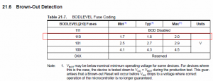
Before we do anything let’s take a look at the ATtiny85’s datasheet, we want to check what voltage range works on.
It appears the safe operating voltage can range from 1.8v to 5.5v. We’ve like to use 2 AA batteries, so this means that when our AA batteries start going flat, once each battery is at 0.9v (0.9 x 2 = 1.8v) it’s the minimum voltage that the ATtiny85 will work properly. The cut off voltage (i.e. when the battery is almost dead) for AA batteries is usually 0.8v so having 0.9v minimum per battery isn’t too bad.
What would happen if we left the ATtiny on 2 AA batteries for x amount of days and then it drops to 1.79v?
It appears all sorts of funny things can happen, one of them being that the EEPROM can become corrupted which isn’t a good thing especially since all our logged data is there.
It also can happen with the ATtiny’s flash as well!
We counteract this issue by enabling what’s called Brown-out detection. It’s like what happens when your home has power issues (e.g. an electricity station overloaded) and you see your lights dim a bit. This sort of thing can damage electrical equipment because it’s running a lower voltage than they should be.
Enabling brown out detection does use some power but it’s a factor you’ll need to take into account if you can’t control your power source over time. What happens is when say 1.8v is detected, the ATtiny85 connects the Reset pin to ground so it stops itself from running.
So we just need to set our BODLEVEL to 110 to set the turn off voltage to 1.8v typical. To actually change the BODLEVEL we need to set a “fuse” on the ATtiny. The Atmel range of microcontrollers contain re-writable “fuses” which control various internals, like the brown-out level, disabling the reset, debugging, etc.
So where exactly do we enter our values for the “fuses”? As an example if you go to your Arduino hardware directory C:\Program Files\arduino-0021\hardware\arduino and open up boards.txt you’ll see the below.
##############################################################

uno.name=Arduino Uno
uno.upload.protocol=stk500
uno.upload.maximum_size=32256
uno.upload.speed=115200
uno.bootloader.low_fuses=0xff
uno.bootloader.high_fuses=0xde
uno.bootloader.extended_fuses=0x05
uno.bootloader.path=optiboot
uno.bootloader.file=optiboot_atmega328.hex
uno.bootloader.unlock_bits=0x3F
uno.bootloader.lock_bits=0x0F
uno.build.mcu=atmega328p
uno.build.f_cpu=16000000L
uno.build.core=arduino

##############################################################
There are many different Arduino boards listed in the boards.txt file as each board has a different setup or configuration. We can see a few things like the board name “Arduino Uno”, the CPU speed “16000000L” which divided by 1,000,000 equates to 16MHz, the maximum size of the sketch “32256” bytes and so on.
uno.bootloader.low_fuses=0xff
uno.bootloader.high_fuses=0xde
uno.bootloader.extended_fuses=0x05
uno.bootloader.unlock_bits=0x3F
uno.bootloader.lock_bits=0x0F
Here’s the part we are really interested in which are the 3 different fuses and unlock/lock bits. Keep this in mind as we’ll need to add and change the fuse values to our ATtiny board.txt in just a little bit.
There’s a nice website (http://www.engbedded.com/fusecalc) that lets you pick your microcontroller and choose which kind of fuse bits to set, or reverse what the current fuse bits set mean.
Firstly choose the ATtiny85 and press select.
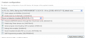
The default values for the ATtiny85 are shown. Can you see the BOD LEVEL that needs to be changed?
Go ahead and change it to BOL LEVEL 110 and press Apply Feature.
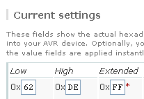
Scroll down a little until you see the fuse bits outputted, these are the ones we’ll use so note these down. Lets jump back to the Arduino hardware folder but this time for the ATtiny (C:\Program Files\arduino-0021\hardware\attiny45_85) and open up the boards.txt file.
attiny85.name=ATtiny85
attiny85.upload.using=arduino:arduinoisp
attiny85.upload.maximum_size=8192
attiny85.build.mcu=attiny85
attiny85.build.f_cpu=1000000L
attiny85.build.core=attiny45_85
The first thing you’ll notice is that no fuses are defined. This is perfectly ok, it just means the ATtiny85 will run off the default fuse values from the factory.
Now in order to upload the fuse bits to the ATtiny85, we have to burn what’s called a Bootloader which is something that runs straight away when you power up the chip. The bootloader can be left empty which is what we will do but you need to re-program the bootloader every time you want to change any of the fuse bits.
attiny85.name=ATtiny85
attiny85.upload.using=arduino:arduinoisp
attiny85.upload.maximum_size=8192
attiny85.bootloader.low_fuses=0x62
attiny85.bootloader.high_fuses=0xDE
attiny85.bootloader.extended_fuses=0xFF
attiny85.bootloader.unlock_bits=0xFF
attiny85.bootloader.lock_bits=0xFF
attiny85.build.mcu=attiny85
attiny85.build.f_cpu=1000000L
attiny85.build.core=attiny45_85
Let’s add the fuses we got from the fuse calculator website and unlock/lock bits, save the board.txt file and re-load the Arduino software.
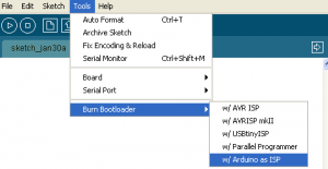
Select Tools -> Burn Bootloaders -> w/ Arduino as ISP.
You can ignore the error messages it gives you about the read operation. Now just re-upload your sketch to the ATtiny85 and it’ll have the brownout detection enabled at 1.8 volts. If the batteries drop to 1.8 volts, the ATtiny85 will pull the reset pin to low and therefore disabling the ATtiny85 from running.
Read the below if your fuse bits didn’t set properly or if you would like to know another way to set the fuse bits without burning the bootloader, I recommend you do!
If this is the first time you’ve burnt the bootloader to the ATtiny85 it’ll work fine but if you try again for some reason it doesn’t work but that’s ok there is another method around it. What we’ll do is use AVRDUDE to read and program the fuse bits ourselves.
Firstly we’ll need to open up a command prompt to C:\Program Files\arduino-0021\hardware\tools\avr\bin.
Make sure your Arduino is connected to the ATtiny85 like you are going to program it and then type in the following to the command prompt: avrdude -C “C:\Program Files\arduino-0021\hardware\tools\avr\etc\avrdude.conf” -p ATtiny85 -c stk500v1 -b 19200 -P COM2 -v
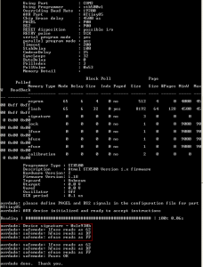
What this does is read the configuration file for Avrdude, specify that we will be talking to an ATtiny85, specify the ISP as a stk500v1, we overwrite the bit rate to 19,200 bits/sec, connect to our ISP using COM2 (this will change depending on what COM port your Arduino is on) and then -v just says output any information you have on our ATtiny85.
We can see there is a large amount of information but all we are interested is in the fuse bits, you can see they are actually still set as the defaults.
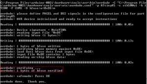
Now we run the following command: avrdude -C “C:\Program Files\arduino-0021\hardware\tools\avr\etc\avrdude.conf” -p ATtiny85 -c stk500v1 -b 19200 -P COM2 -U hfuse:w:0xDE:m
This is like the first command except this time we use -U and say we want to do something with highfuse (hfuse). We say we’d like to write to it (:w) the value 0xDE (:0xDE:m).
You’ll see the above come back which it looks like the fuse bit was successfully set so we’re all good now! I’ve tested it out and it does work as intended, please view the video to see the changes.
Thanks for reading, in the next part we’ll cover the changes to the code and components to actually make our Standalone Temperature Logger work at 1.8 volts minimum.






Hey thanks!
This tutorial really helped me understand how to change the fuse settings in an ATtiny85. (via Avrdude.) Your writing is clear and thorough, and the videos really put it together. Thanks for taking the time to do this.
BTW I liked how you rolled your own TWI. You also might be interested in master and slave TWI libs I just finished for the ATtiny85. You can get them here:
http://www.arduino.cc/playground/Code/USIi2c
Thanks again, and good luck on your projects.
Thank you for your feedback 🙂
I’ve taken a look at your TWI libs and they look good, nice work! I’ll be sure to use them (I was always thinking to myself how am I ever going to use a I2C EEPROM with the ATtiny if any of my projects needed it)
I checked your website and saw you’ve recently found out about the watchdog interrupt for sleep mode, me too I just discovered it last week 🙂
I have a program setup on an ATtiny85 that has a pushbutton to select one of several modes. Currently when I have a power failure the mode selection clears, when the circuit is powered up you must reselect the mode that was last in service. Would brown out detection allow the ATtiny85 to resume it’s previous mode selection on power up? If not, do one of the other fuse selections allow for this?
Hi Mike. The brown-out detector only works to essentially cut the power to the ATtiny if it detects the voltage drops too low, so it won’t suit your needs.
What you need is to use internal EEPROM, a place where you can store bytes of data, for the ATtiny85 it’s 512 bytes. All you would need to do is store the current mode into the first address of the EEPROM.
An example of reading and writing to an EEPROM can be found on the Arduino software examples by going to Open -> EEPROM -> eeprom_read or eepromwrite. A tutorial can be found here – http://tronixstuff.wordpress.com/2011/03/16/tutorial-your-arduinos-inbuilt-eeprom
Hi,
you are refereing to ATTiny85V, aren’t you? Ordinary ATTiny85 is only down to 2.8V.
Best
Andreas
Hi Andreas, yes that’s right I was talking about the ATtiny85V.
hello,
i am having a problem with my attiny85 it works fine when i connect the power source with my laptop but as soon as i connect it with the dc charger (my phone charger) it works only first time then it stops working can you let me know the reason. please is it because BOD disable?
Hi Hirdesh,
Could you advise the voltages of the laptop power source and the dc charger/phone power source?
If you set BOD like in this tutorial, it’s set to 1.8V typical and most phone chargers are 4-5V so it’s unlikely that it’s BOD.
You can calculate the fuse bits by going to this site and selecting ATtiny85 – http://www.engbedded.com/fusecalc
If you turned off BOD and still have issues, I would try adding a 100uF capacitor near the ATtiny.