I’ve decided to come back to this project after learning how to use the ATtiny’s ADC in differential mode. With the ATtiny44A we can use a gain of 20x for the differential mode and if we used a 1 ohm resistor with a load of 100uA, it would give us reading of 2mV (0.1mV x 20) which means we could remove the op-amp from our circuit.
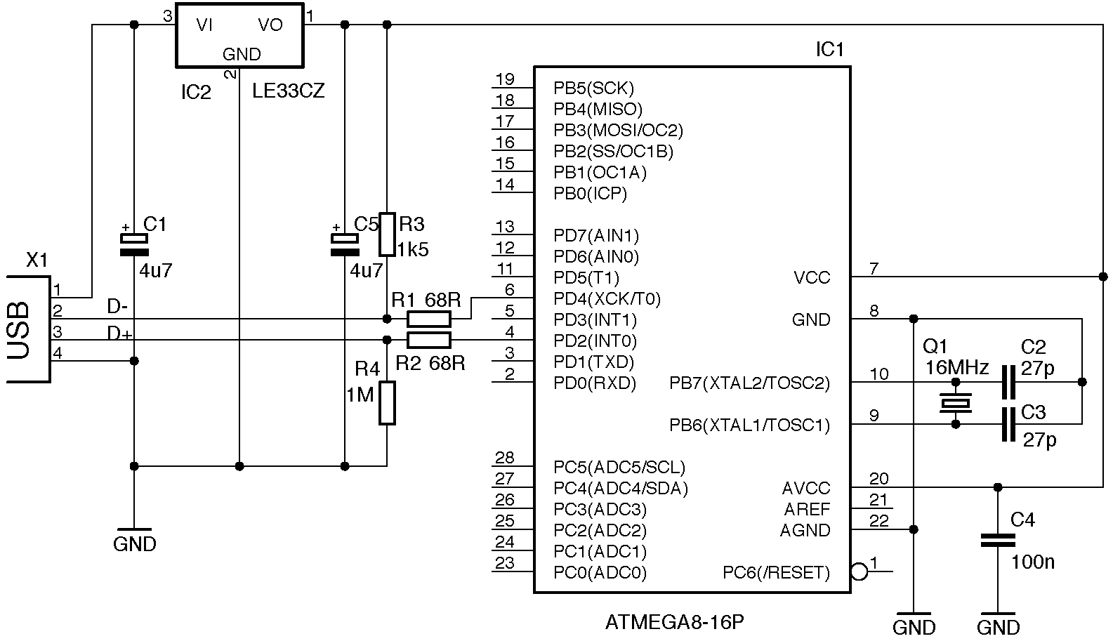
I also wanted to remove all the level shifters from the circuit and have it all powered by the USB instead of using a battery. There was an example of a V-USB circuit which used a 3.3V low voltage dropout regulator and I was able to get my hands on an LP2950.
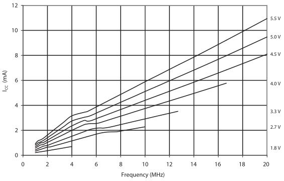
Since we will be running the ATtiny44A at 3.3V it can’t run at 16MHz but it can run at 12MHz and V-USB supports this too (if we didn’t get the ATtiny44 “A” version then 12MHz at 3.3V isn’t supported).
I decided to test out the differential mode on 20x gain because I hadn’t done that before, the results were some what different to what I expected. On a low reading such as 2mV it didn’t seem to give reading, it just stayed at 0 while I was expecting a reading of 40. Increasing the voltage drop on the resistor a bit more didn’t seem to give results of 20x gain either. When increasing the drop on the resistor even further to the point when the result read between 400-500 that’s when the 20x gain was sort of most accurate.
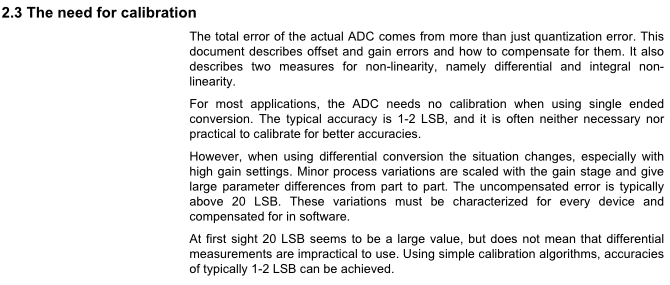
There is a PDF from Atmel titled Characterization and Calibration of the ADC on an AVR which says that when using the differential mode especially in high gain there can be a error of 20LSB and that calibration is required to reduce this typically to 1-2LSB.
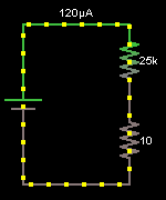
But I don’t want to calibrate the ADC. If we re-arrange the circuit we could simply move the shunt resistor to ground and not have to use differential mode at all. We can now use single ended mode and instead of a 1 ohm shunt we increase it to 10 ohms. At about 10mA of current flowing, we’ll get a voltage drop of 100mV and 10mA will be close to the maximum I would want to be measuring.
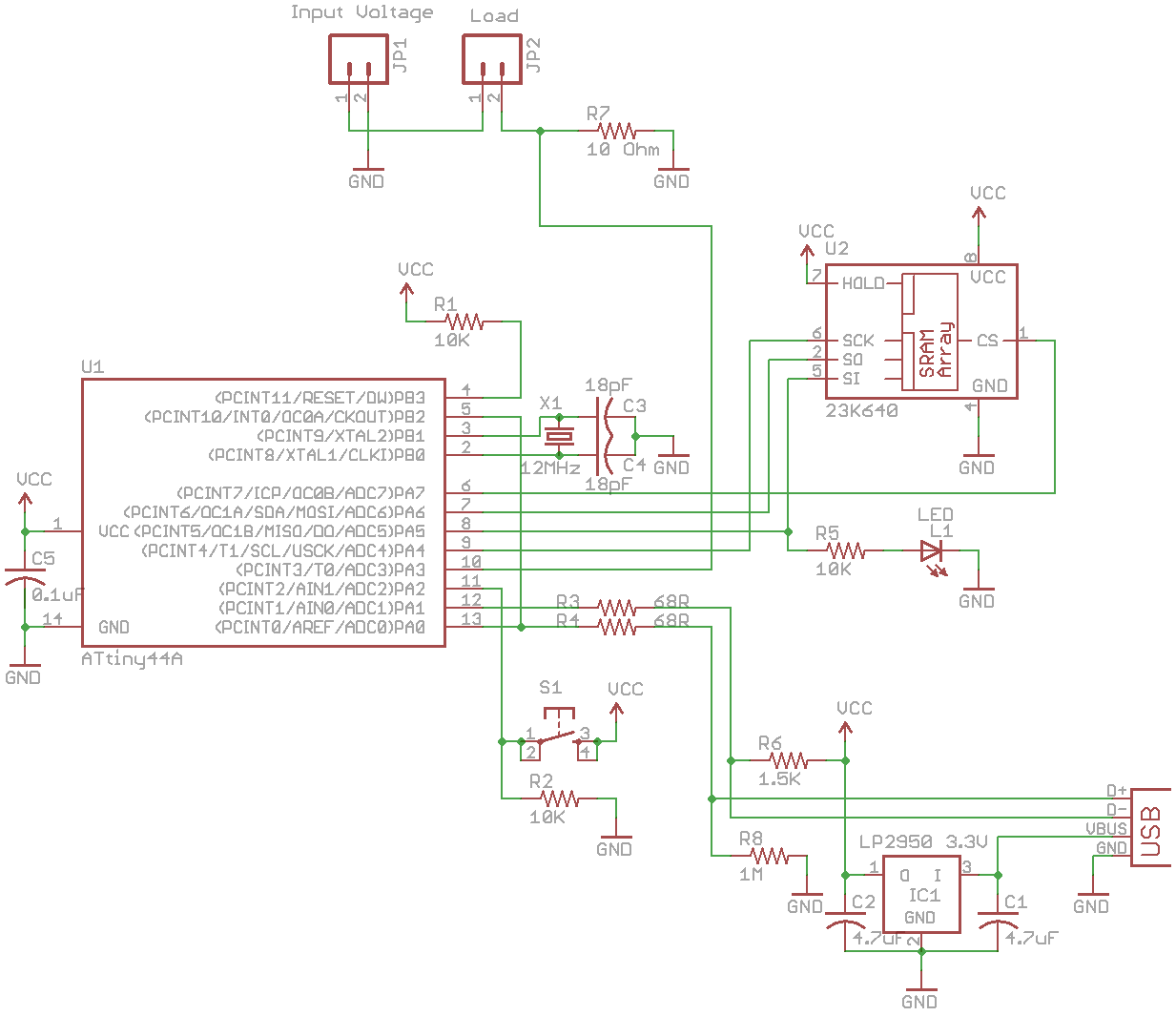
Here’s how the circuit looks now, much more simpler than before.
After testing it appears to be working correctly, with a static load it seems to have an accuracy of 0.2mA which is less than what we got with the op-amp but we now have less parts so I’m happy with that.
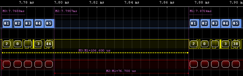
Since we dropped down to 12MHz, for our ADC clock we divide by 64 to give 187.5KHz which is faster than the 16MHz with ADC clock at 125KHz. It now only takes 106us to perform the ADC conversion and write it to the SRAM. With a 256Kbit SRAM we should be able to log 1.6 seconds.
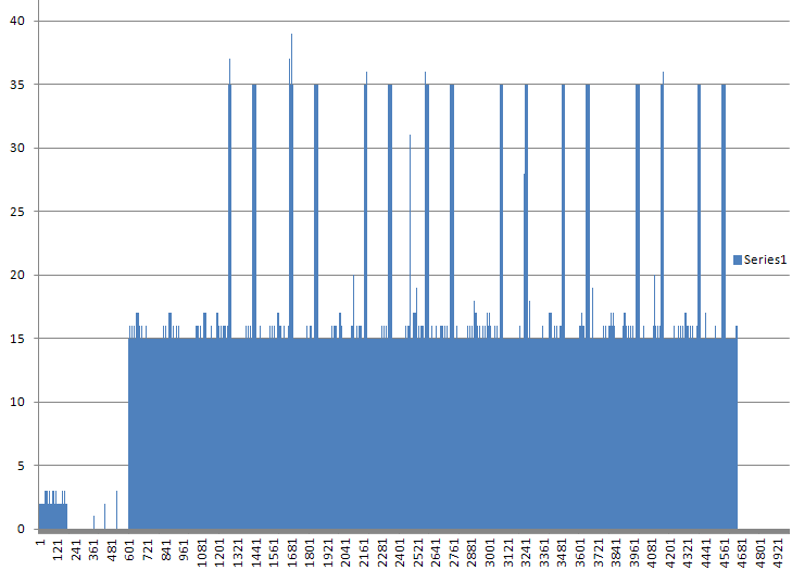
19
12
19
12
19
20
331
20
11
19
12
12
19
12
However I’ve noticed some large spikes (such as 331 as above which means 33mA) which isn’t possible with the load I was using (I was testing the SATVL).
if (nBytes > 0) {
  int number = atoi(buffer);
  if (counter >= 5) { // If counter is higher than 5, we can start checking the averages

    // Move the newer number to the end of the array and move the rest of the numbers down one
    int x = 0;
    for (x = 0; x < 4; x++) {
      averaging[x] = averaging[x+1];
    }
    averaging[4] = number;

    // Average all 5 results
    int average = 0;
    for (x = 0; x < 5; x++) {
      average += averaging[x];
    }
    average = average / 5;

    // Check if the average number is more than 0, if not then we'll crash if we try the below
    if (average >= 1) {
      // We work on the middle number, after dividing it by the average, if it's more than 2
      // then we should ignore the result because it is too far away from the average
      if (!((averaging[2] / average) > 2)) {
        printf("%i\n", averaging[2]);
        char tempbuffer[10];
        sprintf(tempbuffer, "%i\r\n", averaging[2]);
        fwrite(tempbuffer, 1, strlen(tempbuffer), pFile);
      }
    }
    else { // Should give us a reading of 0
      printf("%i\n", averaging[2]);
      char tempbuffer[10];
      sprintf(tempbuffer, "%i\r\n", averaging[2]);
      fwrite(tempbuffer, 1, strlen(tempbuffer), pFile);
    }
  }
  else { // Start adding the numbers to average array until we reach 5 numbers
    averaging[counter] = number;
  }
  counter++;
}
I wrote a software filter which uses averaging to determine if there is a spike between the normal results, if there is a spike it’s ignored. For example, if we got up to the result of 331, the average of the 4 numbers around it including the 331 number would be 80, then we divide 331 by 80 which gives 4.1 that’s more than 2 (a number I chose to compare to based on testing). If we tried it on the next result of 20, the average is 80, then we divide by 80 which gives 0.25 so it’s recorded.
Here are the results with the software filter when the SATVL is first starting up and performing the EEPROM tests, when the EEPROM is written to the total current used is 3.5mA which seems correct. Download SACL_v0.5
Having a total logging time of 1.6 seconds may not be long enough for some projects, you could easily increase that time by having some delay after the ADC conversion. If you delayed 1ms, you would get a total logging time of 17 seconds.
That’s all for now, I have been playing around with a 13bit external ADC so potentially we could switch back to a 1 ohm shunt resistor.


