As the nRF24L01 modules are so cheap I bought quite a lot of them and have been thinking about networking them together. I have the idea of using nRF24 to be able to find out which other nRF24’s are around then then eventually be able to forward traffic for one another if it can’t communicate with a nRF24 that may be too far away but that’s an idea for later on.
The nRF24L01 allows for up to 6 receive addresses but I want to make this much higher so the way I decided to do this was through software and it would allow for up to 255 addresses. It would use all 32 bytes of data that we can send and its format is:
- From address (byte 0)
- To address (byte 1) – address 0 means it’s for everyone
- Forward address (byte 2) – 0 means it’s a normal packet, 1-255 means to forward it to the address
- Acknowledgement (byte 3) – 0 means no ack is needed, 1 means ack is needed back, 2 is the ack to send back, 3 is the ack to send back when forward is complete
- Data (byte 4 to 31)
Here’s an example of how it would look:
FROM    TO    FWD    ACK    DATA
1       2     0      1      12345
2       1     0      2
We will be using just 1 address for the RX and TX addressing which means that every module has the same TX/RX address so we need to disable auto acknowledge and auto retransmit otherwise each module would auto acknowledge each other, we’ll implement this functionality ourselves. Download nRF24_Multi-Network_v0.1
Transmitter
data_out[FROM] = MYADDR; // Our address
data_out[TO] = 2; // Address 2
data_out[FWD] = NOFWD; // No forwarding needed
data_out[ACK] = YESACK; // Ack our packet
data_out[DATA] = 12345;

if (send_packet_wait_ack()) {
  PORTB |= (1<<PB2);
  _delay_ms(500);
  PORTB &= ~(1<<PB2);
  _delay_ms(1000);
}
We setup the transmitter details.
// Send a packet and wait for an ack back, times out after 10 ms
uint8_t send_packet_wait_ack(void) {
  uint8_t packet_retries = 0;
  while (packet_retries < 2) {
    mirf_transmit_data(); // Transmit data
    if (mirf_receive_data()) { // Wait to receive a packet
      // Check the ACK
      if (data_in[FROM] == data_out[TO] && // Coming from who we sent it to
        data_in[TO] == MYADDR && // Packet intended for our address
        data_in[FWD] == NOFWD && // Same FWD type
        data_in[ACK] == ACKRESPOND) { // ACK is respond type

        return 1;
      }
    }
    packet_retries++;
  }
  return 0;
}
We transmit the packet and wait to receive a packet back, we check to see if the packet we received is addressed to us and matches what we sent, we do this 2 times.
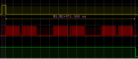
The yellow shows CE pulsed for 15uS and the green shows when the transmission was received by the receiving module (green going low). I found that transmitting data, that it can take between 500uS to 570uS or so.
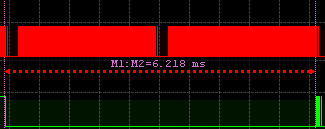
It takes about 6ms for the receiving module to read out the data and write the reply data at 1 MHz, so we should be transmitting for all the time just in case the receiver didn’t receive the packet the first few times because like above if it was just reading out the data it wouldn’t be listening.
There have been some times when even after trying to send the packet 8 times that it didn’t go through which is why I have it re-initialise itself and resend it another 8 times.
TX_POWERUP; // Power up to transmitter mode
mirf_flush_rx_tx(); // Flush RX and TX FIFO

mirf_CSN_lo;  // Pull down chip select
spi_transfer(W_TX_PAYLOAD); // Write cmd to write payload
spi_write_data(data_out, mirf_PAYLOAD); // Write payload
mirf_CSN_hi; // Pull up chip select

// Reuse TX Payload, it takes 5ms for the receiver to read out RX Payload so re-send the packet a few times to ensure they get it
for (int x = 0; x < 8; x++) {
  mirf_CE_hi; // Start transmission
  _delay_us(15);
  mirf_CE_lo;

  _delay_us(500); // Wait until packet is transmitted

  mirf_CSN_lo;  // Pull down chip select
  spi_transfer(REUSE_TX_PL); // Write cmd to reuse last payload
  mirf_CSN_hi; // Pull up chip select
}
// We always flush TX/RX before sending/receiving so we don't need to do it here to void the Reuse TX PL
Inside the transmit function, we transmit the packet 8 times, wait 500uS and then use the Reuse TX payload function to re-use the payload that’s in the nRF24 already for our next data transmission.
Receiver
RX_POWERUP;
mirf_flush_rx_tx(); // Flush TX/RX
mirf_CE_hi; // Start listening

// Wait for incoming requests
while (!(mirf_status() & (1<<RX_DR))) {
  _delay_us(50);
}
mirf_CE_lo; // Stop listening

// Read the data received and process the packet
if (receive_packet_and_process()) {
  // Blink LED
  PORTB |= (1<<PB2);
  _delay_ms(50);
  PORTB &= ~(1<<PB2);
  _delay_ms(50);
}
We just wait for a packet and then process it.
uint8_t receive_packet_and_process(void) {
  // Clear the data_in
  for (int x = 0; x < 32; x++) {
    data_in[x] = 0;
  }

  // Read the payload
  mirf_CSN_lo; // Pull down chip select
  spi_transfer(R_RX_PAYLOAD); // Send cmd to read rx payload
  spi_read_data(data_in, mirf_PAYLOAD); // Read payload
  mirf_CSN_hi; // Pull up chip select
  mirf_config_register(STATUS,(1<<RX_DR)); // Reset status register

  // Check the packet if it was intended for us, otherwise exit
  if (data_in[TO] != MYADDR) {
    return 0;
  }

  // Check if an ACK is required
  if (data_in[ACK] == YESACK) {
    // Clear data out
    for (int x = 0; x < 32; x++) {
      data_out[x] = 0;
    }

    data_out[FROM] = MYADDR; // From our address
    data_out[TO] = data_in[FROM]; // Send back to the address that we received this packet from
    data_out[FWD] = data_in[FWD]; // Set FWD to same type
    data_out[ACK] = ACKRESPOND; // Ack respond

    // Send the ACK
    mirf_transmit_data();

    // We assume our ACK made it if we don't heard back in 10 ms (seems to give the best results)
    uint8_t wait_retries = 0;
    while (wait_retries < 2) {

      // Wait for packets
      if (mirf_listen_5ms_timeout()) { // If packet received
        uint8_t temp_data_in[32];

        mirf_CSN_lo; // Pull down chip select
        spi_transfer(R_RX_PAYLOAD); // Send cmd to read rx payload
        spi_read_data(temp_data_in, mirf_PAYLOAD); // Read payload to temp variable
        mirf_CSN_hi; // Pull up chip select
        mirf_config_register(STATUS,(1<<RX_DR)); // Reset status register

        // Matches data in we received at the start?
        if (data_in[FROM] == temp_data_in[FROM] &&
          data_in[TO] == temp_data_in[TO] &&
          data_in[FWD] == temp_data_in[FWD] &&
          data_in[ACK] == temp_data_in[ACK]) {

          // Send the ACK
          mirf_transmit_data();
        }
      }
      wait_retries++;
    }
  }
  // Process the packet

  return 1;
}
We read out the payload, if it wasn’t for our address we exit. If an acknowledge is required, we set our data out and send the acknowledgement. After 6ms or so of transmitting acks, we start listening for 5ms which is in case the transmitter thinks we never received any of it’s 8 attempts of sending a packet to use and if it matches the packet we received at the start we send another 8 acks back.
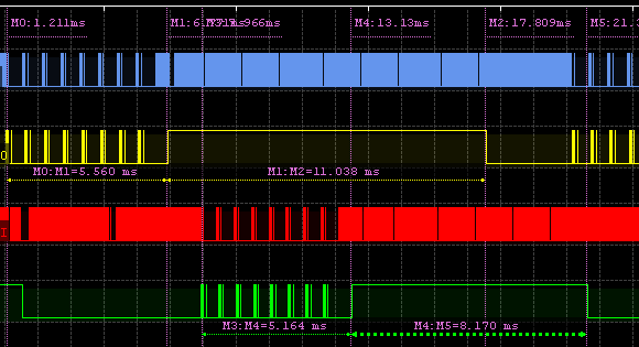
Here’s an example, on the top we have the transmitter (TX) and the bottom is the receiver (RX). The RX has received the packet and tries to send an ack back but the TX never received it. The TX tries to re-send the packet which the RX receives (and later on the RX will send it’s ack back).
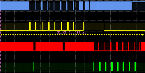
If the transmit and receive works on the first 8 attempts then we can see it takes 15 ms from TX packet load to the RX end, it will take almost double this time if it fails after 8 attempts.
https://www.youtube.com/watch?v=7Ud9NtIsXoM
We have 2 receivers on the left and the transmitter on the right, the TX sends a packet to each one and you see their LED blink when they send an ACK back, works well.


Dear Alex,
I am trying to do a network that allows a receiver to read the data from transmitters that send the data of the sensors. Each nrf24 sends the sensor data to the receiver, that actuates like a central. Do you think it’s possible to do this based on the code made by you? Your code helped a lot. I am using a msp430, from Texas Instrument.
Regards,
Marlos
Hi Marlos,
Yes that’s possible, if you have less than 6 modules transmitting sensor data then you can modify my example here – http://www.insidegadgets.com/2013/01/05/front-door-pir-detector/ or here – http://www.insidegadgets.com/2012/08/22/using-the-nrf24l01-wireless-module/ and give each sensor a different address. That will make it easier than adding on this software solution.
If you did have more than 6 modules transmitting sensor data, you can give them all the same address as long as they don’t send data at the same time and have the first byte of data be the address and the next bytes be the sensor data.
Hi Alex,
I have some problem when transmitting sensor(nrf24l01 more than 2 nodes). Can you help me to find the solution?! ( each sensor a diffirent address, I think it right but i can’t know how to do it).
I using Arm to code.
Hi Songoku,
What sort of issues are you experiencing? Does it happen if only the TX and only 1 RX are on? Have you tried any example code and does that work?
I have 2 NRF 24L01 modules, one acting as Tx and another as Rx.
Let us assume Tx transmits in particular RF channel.
Is there a way on the Rx module to scan and find out which RF channel the Tx is transmitting (i.e kind of snooping).
I tried to read the CD or RPD bit on the Rx when there is no transmission. This bit is supposed to be set only when a carrier is detected. However I get CD or RPD = 1 all the time on the receiver.
Can you please let me know whether what I am tring is achievable
Hi Krishna,
I played around with the RPD today and I was seeing 0 all the time until I found out that RPD has to be read very quickly otherwise it’s reset to 0.
I made a simple RPD counter which scans each channel, code here: http://pastebin.com/KgJY5ye5
The RPD can be influenced by other wireless devices such as microwaves, wlan routers, etc and due to this fact, I wouldn’t recommend using RPD as a way to detect which channel the TX is on unless you are sure there will never be any interference.
Otherwise, if your TX can transmit say 1 packet a second on the channel it’s on, then you can switch into each channel with your RX, wait for 1 second, read the RX_DR and if no packet is there, go to the next channel. The speed of your channel switching depends how many packets you set your TX to transmit every second.
Hi Alex
Many thanks for replying, my original post has lot of typos as I was half asleep when I posted it last night 🙂
As you mentioned looking at RPD may not work in my case as I am surrounded by 802.11 🙂
I have described my problem below and if you can think of a different solution please advise, I am a newbie with NRF.
I have a remote control which uses NRF to communicate with a base station. I SPI sniffed the line between the micro controller to NRF inside the remote control and demodulated the protocol between the base station and the remote.
The remote acts as a receiver all the time and the base station sends out a keep alive signal on a particular frequency with the Data pipe address pointing to the remote. In the auto acknowledge message the remote sends the key press data.
I got the address of the remote from the SPI message between the microcontroller and the NRF in the remote i.e a write message to RX_ADDR_P0 register had the address.
Using the above address, I am able to mimic the functionalities of the base station using my own setup i.e a Microcontroller and a NRF break out board and able to communicate with the remote. So my microcontroller is able to receive data from the remote and send data to it as well.
I re-packed the remote and removed all the solder wires, with out investigating another scenario. i.e the remote had a synchronise button, so is the base station, this is to pair new or additional remote controls to the base station.
When new remote gets added to the base station using Synch, I assume that the remote becomes a Tx and the base station a receiver on a pre-determined channel. I also assume that all the remote’s are hard coded with the base station address. During the Synchronization process, the remote seems to send its address to the base station so that the base station updates its database.
I need to figure out how the remote transmits its address to the base station.
The logical but harder method is to sniff it again.
I am just trying out whether I can scan the channels and find out the Tx address of the remote when the synchronize button is pressed on the remote. Instead of random scanning, I can probably scan on a limited channels which I have figured out during my earlier sniffing. But even if I manage to find a CD/RPD on that channel, will I be able to find out the Tx address ? Am I on a wild goose chase in following this method?
With the CD/RPD method if you ever manage to find the channel they were transmitting on, there is no easy way to find the Tx address of the transmitter because the nRF only accepts packets to put in it’s Rx buffer if it matches the Rx address you set up beforehand (there isn’t any way that I know of to set the nRF into “listen to all packets to any RX address” mode).
How do the base station and remote addresses look like, are they random?
Maybe the base station address never changes but as you say they both change to a specific channel? If so, then you could try hopping to each channel and listening with the base station RX address when you press the sync button.
I just bit the bullet and re-soldered the wires. Looks like during synchronisation the remote still acts as a receiver but on a different address (which is shared by all remotes and the console probably knows this). The base station broadcasts a 10 byte data during this synchronisation, on receipt of that message the remote sends its unique address in the acknowledgement.
Dear Alex,
I am a hobby programmer and use ATmega8 /32 for my activities. Inspired by your posts , I bought a pair of nRFs and used it for a Tx / Rx pair with ATmega8 16MHz as Rx and ATmega32 16MHz as Tx. To my surprise , It worked like a charm in the First Go. ( after a small change in SPI_Transfer routine – added an extra variable to transfer SPDR to it and return the same from the function).
It is really nice of you to help us by taking so much pain in writing such exhaustive posts. Thanks a Lot !.
BTW , I am not getting the range . In fact , I switched Off my Router , but still I can not get it through from room to the other though it works flawless on line of sight. Any thoughts ? Tx running @3V and RX at 3.3V.
Hi Ashis, Good to hear it worked for you.
About the line of sight, what kind of material do you have in-between the walls? I have standard (non-brick) walls, and I have the nRF going through 2 walls about 10cm / 15cm wide and it’s about 10 metres away without issues.
Do any packets make it through? Are the nRF still facing each other behind the walls? (mine are)
Can you connect your MCU to a serial monitor for the RX side, output the status register to see if anything changes after a while and maybe have an LED blink if the RX received a packet?
Dear Alex ,
Last night , I powered the TX @3.6V instead of 3V as earlier and I could roam around my home from one room to other and get the packets through to the Tx at 3.3V. Thank you very much once again. I will wait for your future posts on data forwarding from NRF to NRF and building a sensor network where any sensor at any part can forward the data to the RX through other sensors in vicinity.
Dear Alex,
thx for sharing the code. I work with AVR studio and i try to compile the code from your website. Unfortunately some errors occured.
Propably the row
#define mirf_ADDR (byte *)”clnt1″
is responsible. What does this line do?
Regards,
Eric
Hi Eric,
That line defines the wireless address of the nRF module. Try using “uint8_t” instead of “byte” or without using define: uint8_t mirf_ADDR[] = “clnt1”;
Hello,
You have a lot here but I just wanted to clarify what can be done with your code. I’m just starting an arduino project using the RF24 libraries. I know in Manicbug’s original library, the design is that a pseudo mesh network can be setup in tree topography; each note can listen to 6 children. Messages pass drown from children to parent and then over to other parents and back up to target children.
So my question is, are you suggesting here that each parent can listen for up to 255 children?
Thanks!
Hi Riccar,
Yes that’s correct, basically we have all the nRF using the same RX and TX MIRF address so that any nRF that sends data will be received by all other nRF. This then means we need to add in the software the FROM and TO address so each nRF can only listen to the packets it needs to process.
Hi Alex.
I find your web project for nRF24L01+ multi network..
I also searching small easy and open sensor network and find you ..
I have question :
1. your network working in start topology .. but use same range extended or not ??
2. what is power consumption of sensor ??
regards
Hi Dzairo,
It’s a mesh topology – any nRF can talk to any other nRF. When they do talk to each other, any other nRF can listen in.
Power consumption in transmit is 12mA for a few milliseconds, for receive it’s the same but it’s up to you as to how long you wish to listen for packets. It runs fine with a 3V coin cell for short transmit/receives.
Hi Alex ..
It’s really good to hear that you make mesh network with nRF24L01+ module.. for GCC no Arduino…
I’m not check code but .. is possible to write more about your solution??
If sensor wake up .. then what ?? Are all sensor synchronized ??? What about latency ?? What is average power consumption of sensor send five packet per sec for example ?? You make any testing ?? You try do it for atmega8 or atmega168 etc.??
I must look to your code , to understand how it work.
Thanks .
Hi Dzairo,
In the example zip, the RX is always listening and the TX just sends a packet and blinks an LED is a reply is received so it’s all up you to on how to implement the rest. There is no sync implemented, latency would probably be 20-30ms per packet but it can be quicker if you increase the AVR clock higher than the default 1MHz. My guess for average power consumption for 5 packets per second would be 12mA bursts lasting 5ms and waiting a few ms to receive a reply x 5 packets, so for 1 second assuming AVR is sleeping the rest of the time – about 1mA at a rough guess. I haven’t tried this on the Atmega.
It sounds like it may be good for you to have 1 RX become the server and have it always listening for any TX from the sensors, you could have the AVR wake up every 8 seconds and check in with the server.
Hi Alex,
very good job, my compliments!!!
i would like to ask you for a little help for my project
i’m trying to make a cyclocomputer with arduino using sensor from Polar, i managed to use the heartrate sensor as it’s shown in this blog.
http://vorticityflux.blogspot.it/2011/11/connecting-polar-wind-chest-strap-to.html
but now i would like to implement it using speed sensor and cadence sensor always form Polar. i suppose that all sensor works on the same channel but with different pipe address, do you have some idea how to find these address of other sensor?
thanx a lot
Hi Simone,
I think the best way would be to probe the nRF24 and when the board starts up, with a logic analyser you will be able to see what it sets the receive address to.
thank you alex,
could you please show me te way to get it? how can i make a logic analyser?
If you don’t have a logic analyser, would you have an oscilloscope? If not, if you have an Arduino maybe you could find a logic analyser for it?
Hi Alex,
i need to use ARDUINO IDE to build your code. Does your code need some special includes in order to works in this environment? As I see in your zip archive, there are many files that I do not know (such as *.idb, *elf). Do these filese needed by ARDUINO IDE?
Best Regards.
Stefano
Hi Stefano,
You can ignore those files, what you need is mirf.c/.h and nrf24l01.h, then check main.c/setup.c on how to use.
Hi Alex,
many thanks. I’ll use them. My future aim will be to develop a wireless home security system, based on that component, and I found your idea (same physical address, more software addresses) very good. Did you never use cryptography for encrypt/decrypt the payload data?
Stefano
Hi Stefano,
Originally I was going to use AES but found that it didn’t fit on the ATtiny84 when also using SHA, HMAC and a 256bit random number. In reality it shouldn’t matter as long as you have verification, because really the server/sensor will just be sending 3 things, arm, disarm and trigger (if you encrypted these, the result would be the same unless you used a nounce but then someone could just replay the message and you couldn’t validate it – if you only encrypted).
For the sensors – I settled on using using a 256bit random number that is run through SHA1 and sent to the server.
The server uses HMAC on the random number and includes the state to the sensor back (plus some other states like rolling code addition). The sensor uses HMAC on the HMAC the server sends back, it compares against it’s own result of the HMAC and performs the state if they match. This gives us validation as we never use the same random number and the server only has a few hundred milliseconds to respond.
If the sensor detects someone, it sends a rolling code to the server which was initialised by the rolling code addition (how many times to increment the rolling code number) from the server.
More information available here: https://www.insidegadgets.com/2012/09/29/alarm-system-modification-part-3-secure-communication/ (there are 13 parts in total so far)
Hi Alex,
many thanks again! I’ll keep you informed on the progress of my project (of course, if you want). Now I’m in a very early stage of the project (the menu section where I can choose which zone I can enable/disable), and I’m still waiting for the sensors from Amazon marketplace (!).
Regards
Stefano
Hi Stefano,
Sure, keep me informed on your progress, do you have a blogging site?
Hi Alex!
Your code is being very useful to me and my project. Thank you very much.
Actually I have included your code inside into another nRF24L01 that uses software SPI. It worked like a charm. I’m using an Arduino Mega as TX and an bare Atmega64 as RX.
I’m not a very skilled uC programmer. May I ask you some questions?
In the function mirf_listen_5ms_timeout(void) what happens when a timeout occurs? I’ve put a 500ms delay on my tx main loop what made this timeout to happen and data still being transmitted/received as expected. Is that ok?
My Arduino Mega will receive data from various (more than six) Atmega64 clients, parse it and send that data to a server using GPRS. Would be great if Arduino could send data packets to those clients too. I know it should be possible but I don’t know the best approach to do it on my main loops. Any advice?
Thanks in advance, I’m devouring all the great knowledgement from your posts! Great stuff.
Hi Willian,
In the mirf_listen_5ms_timeout function, we are hoping that it does timeout. We send an ACK to the nRF address we received a packet from and then we listen for 5ms to see if we receive an identical packet that we’ve just ACK’d; if we receive another packet, then we know the transmitter didn’t receive our ACK.
It’s mostly used to line up the receiver and transmitter together after the receiver has read out the packet received because we are running slowly. If you wanted to, you could might be able to remove “// Wait for packets, if we receive another packet the same, send another ack” part if you boosted your clock speed to say 10MHz+.
Sounds like an interesting project, it should be as simple as reusing the TX loop example but just changing the addresses, then on the RX side after the “data_out[ACK] = ACKRESPOND; // Ack respond” part, you can add your data to data_out[DATA]. On the TX side, in the “if (send_packet_wait_ack()) {” you need to read out the data_out[DATA] variable. If you need to add more than 1 byte, you will need to adjust the payload size in mirf.h and use say data_out[DATA+1], data_out[DATA+2], etc.
Hi Alex,
i am working on the project where I am making a network4 nrf24l01 transceivers, such that one can broadcast the text message from one transceiver at the base station to all the other transceivers connected to it. After receiving the message, the transceiver should reply back to the base station in same manner.
I am using 4 nrf24l01 and 4 Arduino Uno boards.
Have you used RF24 Network library?
I need your some guidance in the coding. What should be the code at base station and what could be the code at other node?
Please help..It’s urgent!!!
Thank you
Hi Divyesh,
If you are using all Arduinos, it’s probably easier to use an Arduino library like the RF24 (https://github.com/maniacbug/RF24). if there will only be 1 server and 3 clients, all you’d need is to set the TX/RX pipes and then you can simply use the auto acknowledgement function so the clients will reply back automatically and you can check for that on the server.
Hi Alex,
Thank you very much for your reply. I looked the examples available on RF24 library. In that there is an example called “starping”. In that example the transceiver at the base station receives messages from other radios and then broadcasts its acknowledgement to all the radios.
Now how can I modify that code, such that the base station broadcasts the text message to all the radios and then the radios reply back in the serial chat manner?
Any suggestions?
The starping example is as below.
/*
Copyright (C) 2011 J. Coliz
This program is free software; you can redistribute it and/or
modify it under the terms of the GNU General Public License
version 2 as published by the Free Software Foundation.
*/
/**
* Example RF Radio Ping Star Group
*
* This sketch is a more complex example of using the RF24 library for Arduino.
* Deploy this on up to six nodes. Set one as the ‘pong receiver’ by tying the
* role_pin low, and the others will be ‘ping transmit’ units. The ping units
* unit will send out the value of millis() once a second. The pong unit will
* respond back with a copy of the value. Each ping unit can get that response
* back, and determine how long the whole cycle took.
*
* This example requires a bit more complexity to determine which unit is which.
* The pong receiver is identified by having its role_pin tied to ground.
* The ping senders are further differentiated by a byte in eeprom.
*/
#include
#include
#include “nRF24L01.h”
#include “RF24.h”
#include “printf.h”
//
// Hardware configuration
//
// Set up nRF24L01 radio on SPI bus plus pins 9 & 10
RF24 radio(9,10);
// sets the role of this unit in hardware. Connect to GND to be the ‘pong’ receiver
// Leave open to be the ‘pong’ receiver.
const int role_pin = 7;
//
// Topology
//
// Radio pipe addresses for the nodes to communicate. Only ping nodes need
// dedicated pipes in this topology. Each ping node has a talking pipe
// that it will ping into, and a listening pipe that it will listen for
// the pong. The pong node listens on all the ping node talking pipes
// and sends the pong back on the sending node’s specific listening pipe.
const uint64_t talking_pipes[5] = { 0xF0F0F0F0D2LL, 0xF0F0F0F0C3LL, 0xF0F0F0F0B4LL, 0xF0F0F0F0A5LL, 0xF0F0F0F096LL };
const uint64_t listening_pipes[5] = { 0x3A3A3A3AD2LL, 0x3A3A3A3AC3LL, 0x3A3A3A3AB4LL, 0x3A3A3A3AA5LL, 0x3A3A3A3A96LL };
//
// Role management
//
// Set up role. This sketch uses the same software for all the nodes
// in this system. Doing so greatly simplifies testing. The hardware itself specifies
// which node it is.
//
// This is done through the role_pin
//
// The various roles supported by this sketch
typedef enum { role_invalid = 0, role_ping_out, role_pong_back } role_e;
// The debug-friendly names of those roles
const char* role_friendly_name[] = { “invalid”, “Ping out”, “Pong back”};
// The role of the current running sketch
role_e role;
//
// Address management
//
// Where in EEPROM is the address stored?
const uint8_t address_at_eeprom_location = 0;
// What is our address (SRAM cache of the address from EEPROM)
// Note that zero is an INVALID address. The pong back unit takes address
// 1, and the rest are 2-6
uint8_t node_address;
void setup(void)
{
//
// Role
//
// set up the role pin
pinMode(role_pin, INPUT);
digitalWrite(role_pin,HIGH);
delay(20); // Just to get a solid reading on the role pin
// read the address pin, establish our role
if ( digitalRead(role_pin) )
role = role_ping_out;
else
role = role_pong_back;
//
// Address
//
if ( role == role_pong_back )
node_address = 1;
else
{
// Read the address from EEPROM
uint8_t reading = EEPROM.read(address_at_eeprom_location);
// If it is in a valid range for node addresses, it is our
// address.
if ( reading >= 2 && reading 250 )
timeout = true;
// Describe the results
if ( timeout )
{
printf(“Failed, response timed out.\n\r”);
}
else
{
// Grab the response, compare, and send to debugging spew
unsigned long got_time;
radio.read( &got_time, sizeof(unsigned long) );
// Spew it
printf(“Got response %lu, round-trip delay: %lu\n\r”,got_time,millis()-got_time);
}
// Try again 1s later
delay(1000);
}
//
// Pong back role. Receive each packet, dump it out, and send it back
//
if ( role == role_pong_back )
{
// if there is data ready
uint8_t pipe_num;
if ( radio.available(&pipe_num) )
{
// Dump the payloads until we’ve gotten everything
unsigned long got_time;
bool done = false;
while (!done)
{
// Fetch the payload, and see if this was the last one.
done = radio.read( &got_time, sizeof(unsigned long) );
// Spew it
printf(“Got payload %lu from node %i…”,got_time,pipe_num+1);
}
// First, stop listening so we can talk
radio.stopListening();
// Open the correct pipe for writing
radio.openWritingPipe(listening_pipes[pipe_num-1]);
// Retain the low 2 bytes to identify the pipe for the spew
uint16_t pipe_id = listening_pipes[pipe_num-1] & 0xffff;
// Send the final one back.
radio.write( &got_time, sizeof(unsigned long) );
printf(“Sent response to %04x.\n\r”,pipe_id);
// Now, resume listening so we catch the next packets.
radio.startListening();
}
}
//
// Listen for serial input, which is how we set the address
//
if (Serial.available())
{
// If the character on serial input is in a valid range…
char c = Serial.read();
if ( c >= ‘1’ && c <= '6' )
{
// It is our address
EEPROM.write(address_at_eeprom_location,c-'0');
// And we are done right now (no easy way to soft reset)
printf("\n\rManually reset address to: %c\n\rPress RESET to continue!",c);
while(1) ;
}
}
}
// vim:ai:ci sts=2 sw=2 ft=cpp
Hi Alex,
I’m trying to set a home automation system using nrf24 modules.
I’m a bit confused if your library is what i need, perhaps you could give me a hint…
Basically the idea is to have a central arduino CPU and a number of slaves to control devices on an off based on time and day of the week, with settings loaded from the central.
Each slave should allow up to 4 on/off outputs and have an address configured by some jumpers (say a 8 bit number) right on the board. The idea is the central broadcasts data to all slaves, in the format id number (8 bit) + data (2 bit). This allows the code on the slaves to be exactly the same and I can have several slaves receiving the same stream. Say for example, if I have 4 outside lights around the house, they could all receive the same control signal.
Currently I am aiming for about 32 different devices within the network.
Would this work? Any suggestions to make my work easier?
Many Thanks
Hi Carlos,
This little library has some things to help you start off with but some other things you don’t need (like forwarding) so I would trim it down.
Since you only need 2 bytes, you can change uint8_t data_in[32] / uint8_t data_out[32] to be [2]. The MYADDR variable in mirf.h for the receiver should be set by your jumpers and we can remove some of the other functions, here’s a simpler version that should suit your needs: https://www.insidegadgets.com/wp-content/uploads/2016/01/nRF24_Multi-Network_TX-RX_v0.1_Simple.zip
NRF24L01 want to get data from 32 channels. How to do?
Hi
If I want to communicate between raspberry pi and arduino with your system, what libraries or alike could I need to use on the raspberry?
Or would you then just connect an arduino to the raspberry?
Hi,
The Raspberry Pi has an nRF24 library so you can use the nRF24 with it directly, here’s an example of nRF24 with RPI and Arduino – http://hack.lenotta.com/arduino-raspberry-pi-switching-light-with-nrf24l01/
Hi Alex
Thanks, but is that compatible with your implementation above?
With this 255 address mod, no it wouldn’t work unless you made the same changes to the RPI side which shouldn’t be too hard.
Hi Alex,
Nice job!
My goal here is to read and send data from 4 sensors to 1 receiver. I have five sets of Arduino Unos + rf24 modules, one set as receiver.
I setup one transmitter to one receiver, it works perfect! After I added second set of sensor reading+sending to receiver, I got two set of readings on receiver. But when I change value on one, both readings are changing. and even I disconnected one, the receiver still reading two set of data.
Now I am confused.
my transmitter-1 code:
#include
#include
#include
#include
int address = 0x28; // 28 is the address
byte byte1, byte2, byte3, byte4;
RF24 radio (8, 10);
float p1 [10];
float t1 [10];
float s1 [10];
const uint64_t pipes[3] = { 0xB3B4B5B6F1, 0xB3B4B5B6CD, 0xB3B4B5B6A3};
void setup()
{
Wire.begin();
radio.begin();
Serial.begin(9600);
radio.openWritingPipe(pipes[1]);
radio.stopListening();
}
void loop()
{
Wire.requestFrom(address, 4); // byte is 4;
if (Wire.available()<=4 <=4) {//
byte1 = Wire.read();
byte2 = Wire.read();
byte3 = Wire.read();
byte4 = Wire.read();
}
long unsigned p_counts = (long unsigned)byte1 << 8
| (long unsigned)byte2;
long unsigned t_counts = (long unsigned)byte3 << 8
| (long unsigned)byte4;
p1[0] = ((p_counts%16384-1638.0)/13107.0*20.0)-10.0;
t1[0] = ((t_counts/32.0*200.0)/2047.0-50.0);
s1[0] = (p_counts/16384);
bool ok=radio.write(p1, sizeof(p1));
ok=radio.write(t1, sizeof(t1));
ok=radio.write(s1, sizeof(s1));
if(ok)
{
Serial.println("Pipe 1");
Serial.println(p1[0]);
Serial.println(t1[0]);
Serial.println(s1[0]);
}
else
{
Serial.println("it failed to send");
}
delay(500);
}
Receiver code:
#include
#include
#include
RF24 radio (8, 10);
float p1[10], p2[10], p3[10];
float t1 [10], t2 [10], t3 [10];
float s1 [10], s2 [10], s3[10];
const uint64_t pipes[3] = { 0xB3B4B5B6F1, 0xB3B4B5B6CD, 0xB3B4B5B6A3 };
void setup()
{
radio.begin();
Serial.begin(9600); // radio.setDataRate(RF24_250KBPS);
radio.openReadingPipe(1,pipes[1]);
radio.openReadingPipe(2,pipes[2]);
radio.startListening();
delay(1000);
}
void loop()
{
if (radio.available())
{
radio.read(p1, sizeof(p1));
radio.read(t1, sizeof(t1));
radio.read(s1, sizeof(s1));
Serial.println(“Pipe1”);
Serial.print (“Pressure= “);
Serial.print (“Temperature= “);
Serial.println (“Status= “);
Serial.println( p1[0]);
Serial.println( t1[0] );
Serial.println( s1[0] );
radio.read(p2, sizeof(p2));
radio.read(t2, sizeof(t2));
radio.read(s2, sizeof(s2));
Serial.println(“Pipe2”);
Serial.print (“Pressure= “);
Serial.print (“Temperature= “);
Serial.println (“Status= “);
Serial.println( p2[0]);
Serial.println( t2[0] );
Serial.println( s2[0] );
}
else
{
Serial.println(“it failed to read”);
}
delay(2500);
}
Transmitter-2 code the same as transimitter-1 besides changes all p1, t1, s1 to p2, t2, s2, and Pipe 1 to Pipe2
Please help. Does the time wrong or can you see what went wrong?
Hi Jianglisha,
It looks like you are just printing out both pipes when running “if (radio.available())”, is there a way to check to see if a pipe actually has data? Maybe if you run radio.read(p2, sizeof(p2)), it will give you back a true/false if it read some data?
E.g.
if (radio.read(p2, sizeof(p2))) {
print values
}
Hi Alex,
I am want to send Data from 6 sensor to 1 receive in real time, and our sensor sampling rate have 1KHz. I have a problem. The transmitter/receive always lose package seriously.
How can i do ?
Please Help It’s urgent !
Hi sir Alex,
Can i make a mesh network using 3 devices that can transmit and receive?
Hi Aries, yes you can.
hello alex,
i want to connect 100 transmitters with single receiver ,i need your help,i am using arduino for all sender and receivers . could you give me some guidance about how can i make this ,how to code arduino for this ,i successfully connected 1:1 NRF24l01+arduino ——tx———->>>>>>NRF24l01+arduino ——rx,
please told me how can i disable auto acknowledgement in arduino .
thankyou
Hi Sachin,
You can disable like this:
thanx Alex , but my question is how i can code for 100 transmitters and one receiver
As you will have 100 transmitters, you can pretty much make them all the same code, set all the hardware registers the same and just have the transmitter number assigned in software, say the first byte of 32 bytes that can be sent. The RX will read the first byte and know which TX sent it.
thanx for reply,
I done with it but when I send data from 3 or more sender at the same time data collision occurs in Rx , can you suggest me something for this problem , sorry for my bad English.
By collision, do you mean that the data being received is incorrect, is it duplicated or is something else happening? Are you flushing the RX? The nRF has 3x 32byte FIFOs, in my code I only use the first one (1 packet), then flush the RX so the rest of the packets in the FIFO are deleted, could this relate to what is happening? If so, you would just have to check the FIFO for any data inside and then read it out so then you don’t have to flush the RX.
Hi Alex
I just fell in love with the work done by you. I have some questions regarding this
let us assume this case i have 50 nrf sensors that send the data at the same time to the same receiver address then is it possible that i could hear and get all the data by flushing fifo or moving the data from the fifo at each time i receive
Hi Virajit,
If it’s sent at exactly the same time, down to the microsecond, then it won’t work, likely the nRF will ignore those as the CRC doesn’t match. You definitely want to communicate with the RX as fast as possible, run at 2Mbps data rate and use interrupt pins to know when a packet has arrived.
There are a few ways you could do it:
– Have to delay each one by a little bit (say 1ms)
– Have several RX modules on different frequencies, so each RX only deals with a few TX if latency is a big issue
– Have each TX know when there packet was acknowledge (enable auto acknowledge) and if it wasn’t received, try send it again a random amount of time later
can i use your example like rs485 network
Hi,
thank you for this awesome tuturial.
Would it be possible to send data from up to twelf nrf24l01 transmitter nodes to one nrf24l01 receiver node at the same time? I’m working with IMU data, so the the tranmission is required to be fast and exact. Could I be using two receivers connected to one arduino, to connect six transmitters to each receiver? Or would this cause to many inferences?
Hi Alec,
You would have to do one at a time separately, if all 12 communicated at exactly the same time, it would cause interference. If the transmissions need to be very fast and almost all at the same time, yes I think you should use as many receivers as you can and just stick them on different RF channels. The MCU would also need to be fast enough to handle reading all the receivers quickly too, a CPLD/FPGA would be great for this.
Hi Alex,
We am trying to make an open-sourced LED Rubick’s cube which can be “instantly” scrambled by an arduino. We thought your nRF24 solution might be able to help us with the number of slaves but wanted your views.
As a background, each Rubik’s cube needs 20 receivers. One receiver for each little edge/corner cube. Each reciever should send color data to onboard addressable ws2812B (2 or 3 LEDs per receiver).
– The little cubes are really small (about 20mm cubed) so a board smaller than about 19mm x 21mm should fit, allowing room for battery and LEDs
– The batteries are small so we need a very low power solution.
– Typically the player will solve a pattern in 15-60 seconds, so request the arduino to push new colors to the cube every 15-60 seconds.
– The cubes don’t need to transmit any data (although some rotation or hall effect sensors in a later version could provide some neat features in the future!)
– Distance from arduino transmitter could be as little as say 25 cm
A simplier option is a 433mhz radio, but those consume a lot of power and don’t seem too reliable with the ws2812 due to timing. Not sure if proximity to so many LEDs would be an issue.
We would welcome any suggestions or comments you or others might have.
Thanks!
Hi,
Yes I would recommend the nRF24 over the 433MHz radio since the distance won’t be very far away.
There are versions of the nRF24 which have a 8051 with some flash if you didn’t want to have an MCU on board.
Keep the data rate at the default 2Mbit/s
1Mbit/son the nRF for the fastest transmission time.You would likely put the nRF to sleep and have it wake up every x milliseconds.
I can think of two ways you could do this:
1. Have each nRF share the same address and use the first byte for the address and second byte for the colour of the first LED, third byte for the second LED, really simple. The downside is that every nRF would be listening and processing every transmission.
2. The better way – nRF shared addresses but each colour is specified as 1 bit for each LED, 6 colours is 3 bits (plus 1 spare value say for off) x 3 LEDs per receiver x 20 = 180 bits / 8 = 22.5 bytes. With auto-retransmit off and auto-acknowledge off, you could have the sender nRF send 23 bytes as quickly as possible / always on, and have each receiver wake up every 100-250ms and that’s all that would be needed, each receiver would know which of the 9 bits corresponded to them.
E.g. 000 = off, 001 = white, 010 = red, 011 = green, etc
Sender sends 00101001 10100010 11xxxxxx etc
Receiver 1/20, would see it all and know to turn LED1 to white, LED2 as red, LED3 as green.
Receiver 2/20, turns LED1 to red, LED2 to white, LED3 to green
Thanks so much for your prompt and detailed Rubick’s cube answer Alex!
Based on your recommendation, I will order a bunch of nRF24 units and give this a try. Maybe I will try your simple solution #1 first to get the ws2812b LEDs up and running, then once the system works, move to your more elegant solution #2.
In the meantime, I will spend some time studying networking and getting all the cube algorythms coded…
Thanks again!
Hello Alex, how are you doing?
I just started a project in which I will need to connect up to 6k nodes. After some searching I found your tutorial and it is terrific. From your point of view:
1. Do you think getting this number of nodes is achivable in sofware just like you set it for 255 nodes?
2. Do you recommend using the nRF24L01 instead of a sub-1GHz equivalent for this number of nodes? I’m worry about interferences with WiFi and BT
In my case the 6k nodes will only receive data, in the worst scenario each node will receive different data from the transmitter. Do you think is better if all nodes have the same address and only assign an unique ID by software, so each node can descrimitate data that is not for it?
In your experience, how many days or months the nRF24L01 can run with 2 coin cell batteries?
Thanks for your time and effort.
Best regards,
Felipe.
Hi Felipe,
6k nodes is quite a lot, you could use 2 bytes as the address, so in software it’s not a problem.
It depends on the environment and the use case scenario, for a small open office with not many walls/rooms or a large open venue, the nRF24 would work well but any office/venue that has lots of walls/rooms I probably wouldn’t use it, a sub-1GHz chip would work better in that environment but it would likely consume more power.
I had an nRF24 running from a 1x CR2032, waking up once every 4 seconds, transmitting and receiving 32 bytes, it lasted around 6 months. If you would have it constantly listening on a 1x CR2032, it’s 13.5mA, plus a few mA for the MCU, looking at 6-9 hours or so.
You also have to account for the on-air time, time to load and send the data, time to read the data, lets say 10ms all up which means 100 packets can be sent per second. You could either send 1 packet to each device (say 2 bytes address and 1 byte data) or combine it all together when you send 32 bytes, that might help a little:
Packet 1 = bytes 0-1 addressing Node 1 with 1 byte data, 2-3 addressing Node 2 with 1 byte data, etc.
Packet 2 = bytes 0-1 addressing Node 11 with 1 byte data, 2-3 addressing Node 12 with 1 byte data, etc.
You could have multiple transmitters on different channels and split up the receivers, say 100 on each channel if timing needs to be quick, otherwise if they are on a single channel it could take 60 seconds to update all nodes, that is if they all receive the packet.
To deal with interference, you could implement some frequency hopping on the receivers, say if the receivers don’t receive any data for 10 seconds, it will switch channels in which you would have to setup multiple transmitters on different channels, say 3 frequencies each receiver can connect to.
Which ever way you go, lots of testing will be required!
hi,
I am trying to do machine network using nrf24l01+. I do no how to start it. If u have any idea means please share with me.
Thank you
Hi, I would start with this introduction post: https://www.insidegadgets.com/2012/08/22/using-the-nrf24l01-wireless-module/
I have a project where I will use on server and 6 clients. The server will consist of a nano and nrf24l01. The clients are pro minis with nrf24l01 and mpu6050. The server device will send a “reset” to the clients and then begin monitoring the mpu6050 data. The clients will send the mpu6050 data back to the sever. So, in short, I ned to achieve bi-directional comms between one server and 6 clients. Is this achievable? Is there a particular library you would recommend?
Thanks in advance for your help. Great turorial too!
Hi Brian,
Yes it’s achievable, I think the Maniacbug library should work fine – https://github.com/maniacbug/RF24 or try this more recent optimised library – https://github.com/nRF24/RF24
6 clients is the maximum that the nRF24 supports so you won’t need any additional software like this post to allow for more clients.
The only thing to consider is when each client will send its data as only one can communicate with the server at a time, you might be looking at a few milliseconds per client, you would just need to test that out (e.g. Client 1 sends data, 5 ms later, client 2 sends data, 5 ms later, etc)
Thanks very much for the reply and the information.
Dear Alex
I want to transmit voice with NRF24L01 from a sender to 30 receiver (NRF24L01) with 100 m distance .
Is it possible ?
Thank you
Hi Reza,
I think it could be possible, just set all receivers to the same address, turn off auto acknowledge. You could have some buffering and since it would only be voice, you could drop the bitrate down quite a bit. I haven’t really worked on audio myself so I could really say the best way to record and encode it but Atmel have an app note all about it – AVR335: Digital Sound Recorder
Hi Alex, i was wanting to know if it is possible to set up a 16 MUX in to ardiino+ nrf24 and transmit to other arduino+ nrf24 with MUX out with only change state commands.
Similar to a irrigation controller and valves but with no wires (sorry for the simplistic meanimgs)
Look forward to your thoughts.
Hi Mark,
Yes you could have the Arduino as the server with the nRF24 and have each client device with it’s own nRF24. The server would have one address and the clients could all have the same address, then you could use the first byte of each packet you send to have the client number there so only the correct client performs the action.
Hi Alex,
THANK YOU! This really sparks my interest.
I have 2 questions, please. It’s a YES or NO so as not to impose on you but I would appreciate any comments.
1.) I have 12 individual, unique sound units which need to receive their own 2-byte commands from a single transmitter (connected to Arduino UNO). . Will your sketches perform this basic exchange if I slightly modify the code to handle my 2-byte “packet”?
2.). If so, can each of the 12 receivers return a 1-byte “completed” status byte to the transmitter ?
Note: The transmitter needs to recognize which unit it’s addressing. For example, UNIT1, UNIT2,….UNIT12.
Thanks. You will save me a week’s work of trial/error and I REALLY appreciate your time.
Best regards,
Bill
Hi Bill,
1. Yes it should work, you just need to add the second byte like data_out[DATA+1] = something;
2. Yes if you enable the data_out[ACK] = YESACK; (it’s on by default). It will try only twice to send the same packet to the receiver, you can of course increase the tries, the delay in between and do something special if you receive the ACK back.
The only problem will be if some of your devices are going to be Arduino connected, you will need to check out https://www.insidegadgets.com/2012/08/22/using-the-nrf24l01-wireless-module/ to use that as a starting point and import this code to that example.
Hello, great material
[Q] is it possible to connect about 100 transmitters (nRF24L01 + arduino pro mini + thermometer) to one receiver
communication every 1min
Or do you have any other idea how to do it?
Hi Maciek,
Yes that shouldn’t be a problem if you give each one a unique software address like in the example and also give each transmitter a bit of a random delay time in between each transmission so that hopefully no transmitter is sending data when another one is.
Thank you for your answer
I think so too, do you know if there is any waiting or caching system?
Because I read about it nRF24L01 and it’s possible to make a stack, do you think it could be helpful?
Or is there an option to check if the main receiver has a free port to send or check it with a checksum?
Best Regards
There is a 3 payload (32 byte) buffer which you can use for incoming packets and there is another one for transmitting packets, once the payload buffer is full, no more packets will be accepted so you have to read it out as quickly as possible.
You could have your code read out the buffer quickly and store it in an array for later processing, there is an interrupt pin you can use which tells you if there is a packet waiting in the buffer.
If you found the 1 nRF receiver can’t handle the traffic, you can always add another one with a different receiving address and split the transmitters up in half.
OK, cool about the second NRF24L01 I was thinking that you can always add but from my calculations it comes out that it should be better
This RF24L01 has 6 possible ports to read at one time 6 * (minute [ms] / 10ms) = 6 * (60000/10) = 36,000 measurements per minute.
So it is theoretically possible to handle these 100 sensors.
There is a 3 payload it is in any RF24L01 or is it an additional element of the system? or is there any digital element that could store data for sending?
and this buffer 32 bits it
for example
(0:0:0,25.00,
0:1:0, 25.00,
0:2:0, 26.00,)
one character = 1 bit? the first line of 12 bits or 2 measurements and would have to send
While it has 6 ports to read, they are mostly there so you can easily see which port has a packet waiting for it (I believe), it doesn’t mean you can send 6 packets at each port at exactly the same time.
It should be possible to have 100 sensors send 1 packet to 1 receiver over the span of 1 minute if you can read out the packets fast and there are no collisions but there likely will be collisions which you need to account for which is where the random delay would come in. One sensor would send at 5 milliseconds, another at 34ms, another at 73 ms, etc.
In my previous comment, I should have said it could be the same or different receiver address as long as it’s on a different channel.
The 3 payload buffer slot (32 bytes each) is in the NRF24 chips. One character would be 8 bits (1 byte), if you send a packet with 5 bytes, it will fill up that payload buffer slot so when you send another packet it will go to slot 2.
If you don’t need this to be real time, then you could wait a few minutes and send a single 32 byte packet with say 10 results to the receiver. But if it is real time, it’s best to keep the packets as short as possible and have it transmit as fast as possible (2 Mbps air rate is the default).
ok, can you do that the main receiver asks each sensor, and it responds.
After the first questioning delay they would have done themselves.
or does the receiver have to know all sensor addresses? is it enough that the sensors know the address of the main receiver?
Yep asking each sensor would be a good solution, the only problem with that is, if you are concerned with battery life, as all the sensors would need to be left into receive mode which is close to 20mA.
The receiver doesn’t need to know all the sensors addresses, just the sensors need to know the receiver address. All the sensors would have the same hardware address but a different software address, you would just need to read out each packet received on the sensors and check to see if it’s really for them.
Ok, so it’s better to make everyone know the master, send him their measurements only if the master knows who wrote and can he confirm the receipt of the data?
Yes all the sensors need to know the master address to send data to. Each sensor would send their data and it’s up to you as to how you would send the sensor number inside the packet.
If the master needs to send a packet back to acknowledge receipt, you can change the TX_ADDR and then it would send a packet back to the sensor from the sensor number it got at the beginning.
Another way would be to make all the sensors have the same address so that the master doesn’t have to change the TX_ADDR side but can just add a byte in the packet it sends with the sensor number.
ok thanks for the reply and help
and your program is written in C? when I add it to the idea of arduino it will work?
It won’t work if you copy and paste it in, but the basics of this post is a software based solution – we use the first byte in the packets received to be the address identifier. It’s probably easier if you take a working example of the nRF for the Arduino and just make the first byte be the unique address of the sender, and have your receiver just check the first byte to see which address it was from.
OK Thank you
Hypothetically speaking, if I offer 3 byte’s of the payload size to increase the address bytes to uint16_t (FROM, TO, FORWARD). Could your software than be used for an amazing amount of 255^2 of nodes? I don’t have an usecase yet but i’m wondering about the possibilities.
Yep, as it’s all software controlled, you could keep going even higher!