I’ve previously bought an alarm system from Ebay and have been making modifications to it such as making the PIRs wireless and added wireless sirens. On our last part, we added a way to check which sensors have checked in.
By using everything that we’ve built and modified, it’s now time to make our own alarm system. We’ll be adding in our own PIR, Door sensor, making a slight change to the Siren and modifying the Server.
PIR Sensor
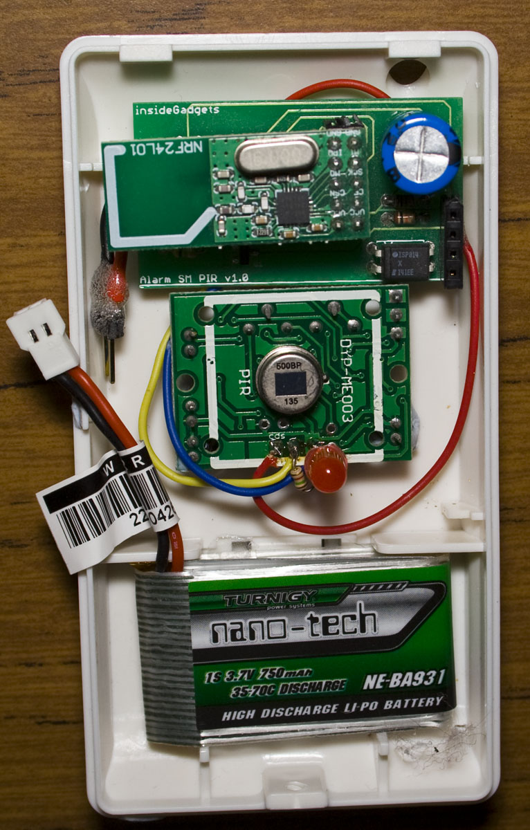
I was thinking about how I could potentially box up the PIR with the PCB but I found that the PIR module you buy from Ebay fits in nicely to the existing casing, I removed the PIR cover and it works well. I’ll be switching from the 3V coin cell to a 3.7 Li-poly so that the PIR and the PCB will run off this which should last at least a few years.
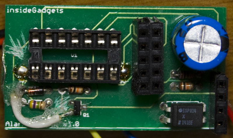
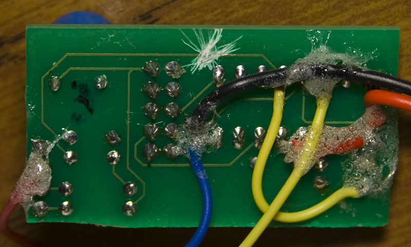
One down side of running from the Li-poly battery is that after testing I found that the PIR is unstable when the voltage drops to 3.3V the PIR automatically turns on. One thing I should have added a while ago was a way to monitor the battery voltage, so we’ll add that this time and the cut off will be 3.5V. A few cuts on the PCB, adding some resistors, re-wiring and it’s ready to go.
If the PIR detects movement, we could modify the existing way to communicate to the server to have the PIR ask the server for a random number, the PIR does a SHA1 with HMAC on it and send that it’s detected movement but this has timing issues. We need a way to send a single command to the server which is where a rolling code comes in, similar to the ones that car remotes use.
Both the server and PIR start off with a 128bit random number, when the PIR checks in, the server provides how many increments to add to the random number. If movement is detected, the PIR can now increment the random number however times the server has previously sent, SHA1 the random number and send that to the server who can verify it the same way.
// 64bit rolling code number (you should change this)
uint8_t rolling_code_base[] = {0x25, 0xF9, 0x34, 0x5A, 0xE2, 0xFD, 0x8D, 0x00,
0x4C, 0x9A, 0xF7, 0x7F, 0x69, 0xD1, 0x3F, 0x82};
uint8_t rolling_code[] = {0x25, 0xF9, 0x34, 0x5A, 0xE2, 0xFD, 0x8D, 0x00,
0x4C, 0x9A, 0xF7, 0x7F, 0x69, 0xD1, 0x3F, 0x82};
uint16_t rolling_code_addition = 0;
Here we’ve got the rolling code base number and the rolling code that gets copied over and the rolling code addition. This transaction will only happen if the alarm goes off, so very rarely (or never I hope!), so I’ve just gone with a 16bit increment.
// Sleep for 8 seconds
if (movement_detected == false) {
  watchdog_sleep(T8S);
}

// Check battery voltage
cbi(PCMSK0, PCINT0); // Remove interrupt to PIR pin so it won't interrupt us
sbi(ADCSRA, ADEN); // Turn on ADC
analog_read(batteryAdcPin); // First reading is ignored
int batteryVoltage = analog_read(batteryAdcPin);
cbi(ADCSRA, ADEN); // Turn off ADC

// If battery voltage below 3.5V then turn off the PIR
if (batteryVoltage <= 555) {
  cbi(PCMSK0, PCINT0); // Remove interrupt to PIR pin
  PORTA |= (1<<PA3); // Turn off PIR (P mosfet)
  system_state = SYSTEM_OFF;
  movement_detected = false;
}
else {
  sbi(PCMSK0, PCINT0); // Apply interrupt to PIR pin
}

// Because we turned off the interrupt, lets check the PIR output
if ((PINA & (1<<PA0)) == 1) { // PIR output high
  movement_detected = true;
}
If movement is detected, we skip the 8 second sleep. We firstly remove the PIR interrupt so it won’t interrupt us, check the battery voltage and if it’s below 3.5V then we remove the interrupt and turn everything off, otherwise we turn the interrupt back on. In the chance that the PIR went high in-between the ADC reading, we’ll check it manually.
if (movement_detected == true && batteryVoltage > 555) {
  // Power up the nRF24L01
  TX_POWERUP;
  _delay_ms(3);

  for (int x = 0; x < 24; x++) {
    data_out[x] = ALARM_TRIGGERED;
  }

  // Start off with the base rolling code
  for (int x = 0; x < 16; x++) {
    rolling_code[x] = rolling_code_base[x];
  }
  // Increment our 128bit rolling code number with the number of increments needed
  ...

  sha1(data_out, rolling_code, 128); // SHA1 of our rolling code

  // Transmit a few times to ensure the server gets it
  for (int x = 0; x < 20; x++) {
    mirf_transmit_data();
    _delay_ms(50);
  }

  // Wait a little while before re-sending
  watchdog_sleep(T2S);
}
If movement is detected, we set all our data out to the alarm triggered type, set up the rolling code, SHA1 it and then transmit it a few times to the server so we know it will definitely receive it.
else {
  // Increment our 256bit random number
  ...

  // Generate the random block (160 bit) using SHA1 from our random number
  sha1(data_out, random_number, 256);

  // Set data_out to say we are a PIR and our sensor number
  data_out[SENSOR_TYPE] = PIR_SENSOR;
  data_out[SENSOR_NUMBER] = SENSOR_NO;
  data_out[BATTERY_VOLTAGE_HI] = batteryVoltage >> 8;
  data_out[BATTERY_VOLTAGE_LO] = batteryVoltage & 0xFF;

  // Power up the nRF24L01
  TX_POWERUP;
  _delay_ms(3);

  // Check in the with server
  if (check_in()) {
    // Perform alarm state action if alarm state received is different to what we have set
    if (batteryVoltage > 555 && system_state != system_state_received) {
      system_state = system_state_received;

      if (system_state == SYSTEM_ON) {
        PORTA &= ~(1<<PA3);
        _delay_ms(20000); // Wait a little bit for the PIR to turn on / adjust
      }
      else {
        PORTA |= (1<<PA3); // Turn off PIR (P mosfet)
      }
    }
  }
}
We now do what we normally do when checking in, SHA1 the 256bit random number, add in the sensor type, sensor number and now add in the battery voltage. Later on in this project, we could have the server light up some LEDs to show which sensors have checked in and which ones have the batteries are low.
ISR(PCINT0_vect) {
  // Battery has been removed, save the random number to the EEPROM
  ...
  else if ((PINA & (1<<PA0)) == 1) { // PIR output high
    movement_detected = true;
  }
  else { // PIR output low
    movement_detected = false;
  }
}
When the pin interrupt is triggered, we check what it’s for, the battery low or PIR high or low.
Door Sensor and Siren
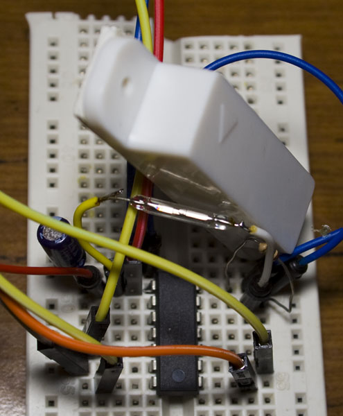
The door sensor uses the same code as the PIR except that we’re using a reed switch with a pull down of 1M, so when the magnet is close to the reed switch, the pin reads high, otherwise it’s low. I can grab the reed switch from the existing door sensor and should be able to re-use the casing too. I’m thinking of running the door sensor off a 3V coin cell because a Li-poly won’t fit well so I may increase the check in time to once every 30 – 60 seconds to increase the battery a bit.
The siren remains mostly unchanged except for changing how we send our sensor type and number.
Server
For the server, the main part is just listening for incoming requests which remains unchanged.
// Check if the request came from a PIR or Door sensor only if the siren isn't on
if (siren_state == SIREN_OFF && (data_in[SENSOR_TYPE] == PIR_SENSOR || data_in[SENSOR_TYPE] == DOOR_SENSOR)) {
  // Add the system state to data_in
  data_in[SYSTEM_STATE] = system_state;

  // Rolling number addition
  data_in[ROLLING_CODE_16BIT_HI] = sensor_rolling_code_addition >> 8;
  data_in[ROLLING_CODE_16BIT_LO] = sensor_rolling_code_addition & 0xFF;

  // Use HMAC_SHA1 on the random number received (160bit) + sensor type (8bit) + system state (8bit) + addition on rolling code (16bit) using the 256bit HMAC key
  hmac_sha1(data_out, hmac_key, 256, data_in, 192);

  // Add the sensor type back in and also the system state to the data_out so the client can use it after it's verified the HMAC signing of the random key
  data_out[SENSOR_TYPE] = data_in[SENSOR_TYPE];
  data_out[SYSTEM_STATE] = system_state;
  data_out[ROLLING_CODE_16BIT_HI] = data_in[ROLLING_CODE_16BIT_HI];
  data_out[ROLLING_CODE_16BIT_LO] = data_in[ROLLING_CODE_16BIT_LO];

  if (!mirf_transmit_data()) { return 0; }
}
...
When a sensor checks in, we check if it’s a PIR or Door sensor and if the alarm isn’t on. We add in the system state, rolling code and the SHA. For the siren request, it’s mostly the same as you can see.
// Remote control requests
if (data_in[SENSOR_TYPE] == REMOTE_CONTROL) {
  // Asking for the latest rolling code
  if (data_in[REMOTE_REQUEST] == REMOTE_ROLLING_CODE) {
    // Rolling number addition
    data_in[ROLLING_CODE_32BIT_1B] = remote_control_rolling_code_addition >> 24;
    data_in[ROLLING_CODE_32BIT_2B] = remote_control_rolling_code_addition >> 16;
    data_in[ROLLING_CODE_32BIT_3B] = remote_control_rolling_code_addition >> 8;
    data_in[ROLLING_CODE_32BIT_4B] = remote_control_rolling_code_addition & 0xFF;

    // Use HMAC_SHA1 on the random number received (160bit) + rolling code addition (32bit) using the 256bit HMAC key
    hmac_sha1(data_out, hmac_key, 256, data_in, 192);

    // Add the rolling number addition back in
    data_out[ROLLING_CODE_32BIT_1B] = data_in[ROLLING_CODE_32BIT_1B];
    data_out[ROLLING_CODE_32BIT_2B] = data_in[ROLLING_CODE_32BIT_2B];
    data_out[ROLLING_CODE_32BIT_3B] = data_in[ROLLING_CODE_32BIT_3B];
    data_out[ROLLING_CODE_32BIT_4B] = data_in[ROLLING_CODE_32BIT_4B];

    if (!mirf_transmit_data()) { return 0; }
  }
We’ll need a remote control to turn the system on and off but but I haven’t built it up just yet, though it’s going to have a similar type of rolling code to the PIR does except that it’ll be 32bit as the remote everyday. When you push the button it will ask the server for the latest rolling code and afterwards it can send the rolling code to the server, this way we don’t need a large capacitor
else { // Verify the rolling code and perform the action
  // SHA1 of our rolling code
  sha1(data_out, remote_control_rolling_code, 128);

  // Verify SHA1 (160 bit) to the client's SHA1
  if (memcmp(data_in, data_out, 20) != 0) {
    return 0;
  }

  // Increment our 128bit rolling code number
  ...

  // Increment the rolling code addition to tell sensors which random number to use
  remote_control_rolling_code_addition++;

  // Turn alarm system on or off
  system_state = data_in[REMOTE_REQUEST];

  // If system is now off, turn off sirens
  if (system_state == SYSTEM_OFF) {
    siren_state = SIREN_OFF;
    // Send alarm off SMS
    PORTA &= ~(1<<SMS_PIN);
  }
}
If the remote control is now sending the rolling code, we verify it, increment the rolling code and then turn the system on or off. Similar code would apply to the PIR’s rolling code.
Download AlarmSM_v2.0
For the next part we’ll look at adding the remote, adding the LEDs to the server, adding battery backup to the server and testing it all out. I’ve also been thinking I could use RFID cards instead of the remotes or perhaps have that as another option of entry as well.
Part 1
Part 2: Two way communication for PIR sensors
Part 3: Secure communication
Part 4: Adding on sirens and SMS sending
Part 5: Modifying the PIR sensor
Part 6: PIR PCB
Part 6.5: PCBs arrived
Part 7: See which sensors check-in
Part 8: Building our own alarm system
Part 9: Remote control and attempted improvements
Part 10: Prototype PCBs


