From our previous post, we made our remote control and looked at making some improvements however we ended up going back to how sensors communicated to the server before. This time we’re building our prototype PCBs and get to test them all out.
(sneak peak of our PCBs working together)
.
Server PCB
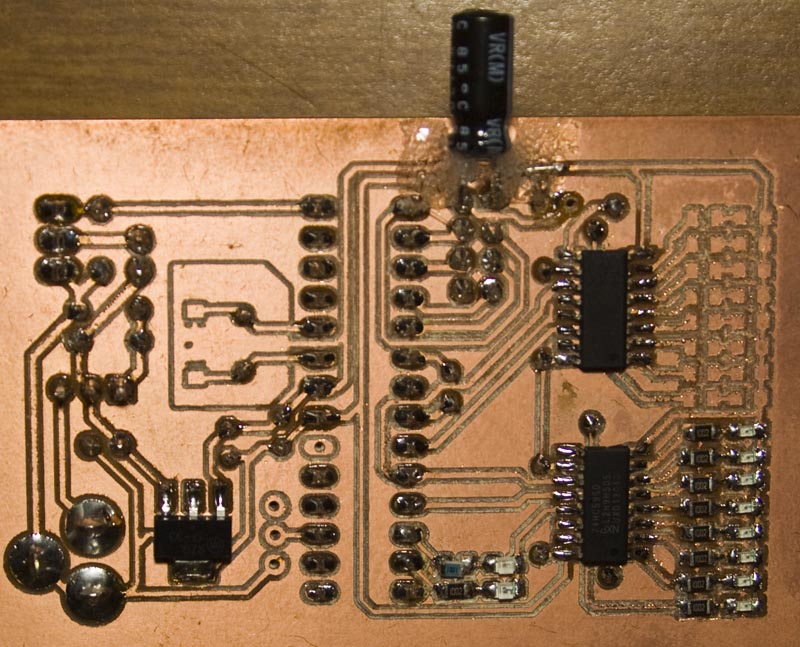
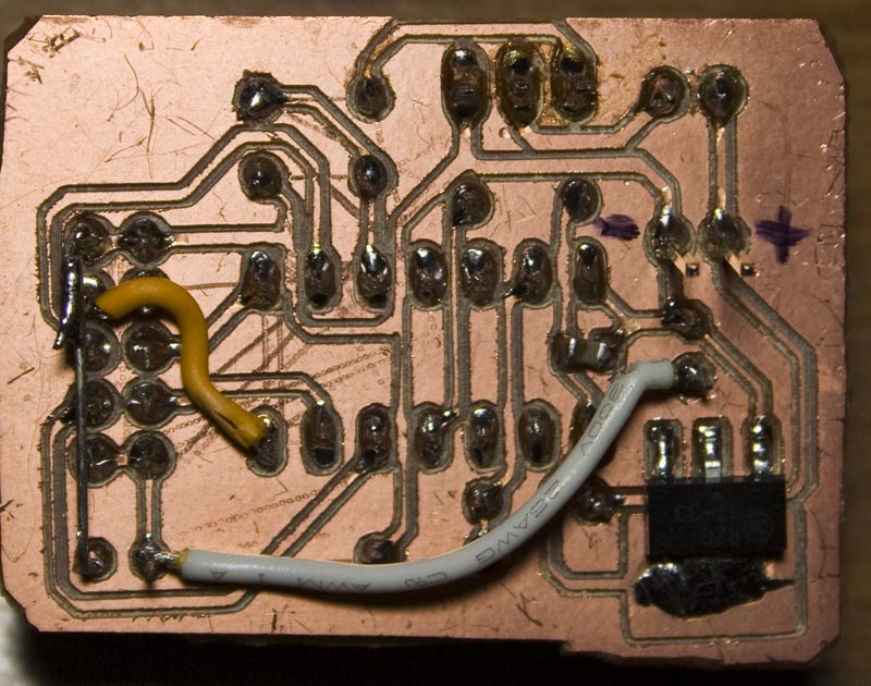
I wanted the server to have a battery backup along with a siren so I took a 15V power adapter and wanted to have some LEDs to display which sensors have checked in with some shift registers to make things easy and now we can have up to 16 sensors. There is also a green LED and red LED used for communication pass or fail, I should of put another LED to shown when the alarm is on. After about a minute or so, the sensor LEDs are reset.
I used the LM317 to reduce the voltage down to 13.5V which is the floating charge voltage for a 12V SLA, the 15V input barely cuts it for 13.5V and doesn’t provide too much current, about 50mA or so. In the end it does run a bit hot so I put in a metal piece on it I had lying around which works good enough. We’ve got a LDO to provide 3.3V to the ATmega328 and nRF24L01+ module, it too runs a bit hot, should have given it more copper. I ended up tearing the pads for the capacitor which is why it’s bodged in there like it is.
.
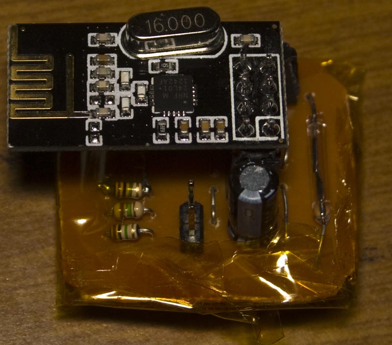
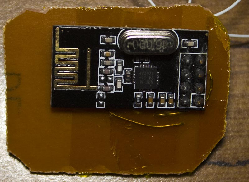
PIR Sensor
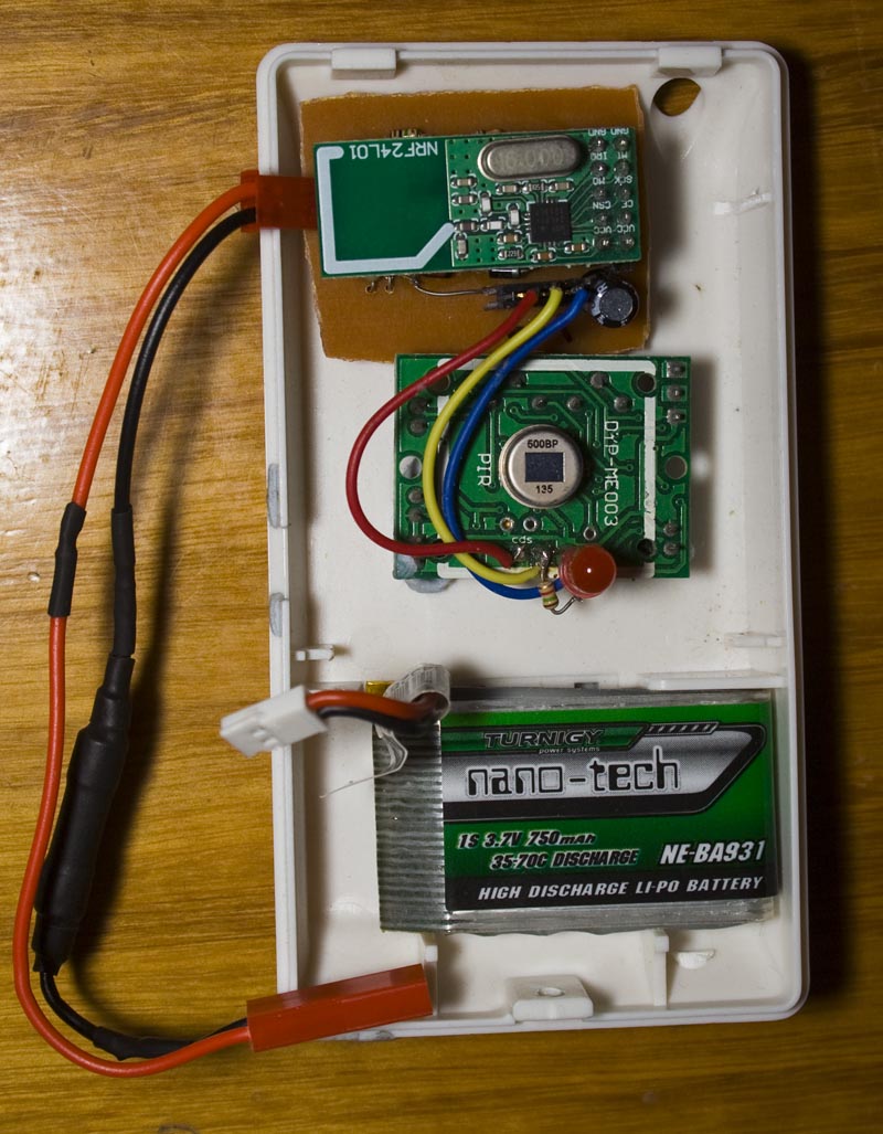
I can’t recall if I mentioned it but the sensors no longer require a large capacitor, I’ve taken the approach that when the battery runs out that the sensor should be re-programmed with a new random number. As a part of every sensor, there is a low battery check, once reaching this the sensor no longer turns on when the alarm system is. On the server, the LED for the sensor blinks every half second if the battery is low.
Since we’re now using a Lipoly a single diode won’t drop it down to a low enough voltage for the nRF, so after testing I found a schottky diode and regular diode works well.
Every since I had mosfet overload and catch on fire in my remote control car, I’m now adding fuses (I had a 250mA the time) to all Lipo devices as they’ll never need more 25mA at a time. As an after thought I forgot to add a 100K resistor to ground the PIR output and it’s just running an ATtiny84.
.
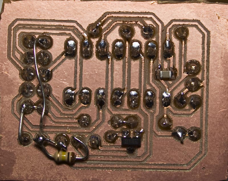
Door Sensor
The door sensor is much like the PIR sensor, it runs an ATtiny84 but to keep it smaller it’s the SMD version and will just use a 3V coin cell which I’ll mount on the bottom. I’ve harvested the reed switch from one of those cheap magnetic sensor alarms found on Ebay. I’ll need to enclose this in a little acrylic or similar box. To program the ATtiny we can just plug in our wires were the nRF is and just add the reset wire. I should add an LED to this so I know it’s working when moving it away from the magnet.
.
Siren
With the siren, I’ll be using another 12V SLA battery this time with an external circuit charging the battery by solar power and using another 3.3V LDO this time with more copper for heat dissipation. We’ve got a small mosfet to switch on the siren and apart from that it’s like the others. The siren does have an low voltage detection like the sensors but this time we don’t turn anything off if the battery is low.
.
Remote Control
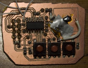
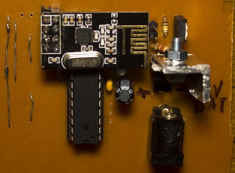
A small compact PCB with 3 switches, ATtiny84 and nRF module soldered on the top. It’s a bit smaller than the remote for the current system but I’ll need to make a case for it too. I’ve got a few small wires used for programming the ATtiny but now to re-program the when the nRF is soldered I’ll need a couple of resistors to reduce the voltage to 3.3V or less. I did have lots of trouble trying to solder the battery to anything really, so I’ll have to buy some CR1220 holders.
We have our 3 buttons – on, off and test. In test mode, we activate the sirens for 50ms and then wait 8 seconds before switching them on again, the PIR’s and door sensors also become active so we can check that they work. When you press any button, the siren on the server activates the siren for a tiny bit so you know it’s received the command.
When trying with a flat CR2032 battery on the remote there was a bit of a strange problem where pressing a button to transmit with the nRF, it would leave the battery drawing about 2mA, I’m guessing that the battery voltage either dropped quite a bit or it just couldn’t supply the current and the ATtiny becomes corrupted because it no longer responds to button pushes after this happens.
Everything’s now working well, now it’s just a matter of making the cases and building up more sensors. One potential problem with all this is that the server has no way to verify that a sensor is giving the correct sensor number / voltage as that could be spoofed.
Download the eagle files and code here: AlarmSM_v2.1 (pardon the remote control PCB layout which was just done without making the traces neat). Oh and if you haven’t noticed the lack of etching on the boards, yes I’ve now got a CNC!
Part 1
Part 2: Two way communication for PIR sensors
Part 3: Secure communication
Part 4: Adding on sirens and SMS sending
Part 5: Modifying the PIR sensor
Part 6: PIR PCB
Part 6.5: PCBs arrived
Part 7: See which sensors check-in
Part 8: Building our own alarm system
Part 9: Remote control and attempted improvements
Part 10: Prototype PCBs


