Back a few years ago when I read the EEPROM of a KVM, we did have an issue where occasionally it wouldn’t switch between computers. A KVM is a keyboard video mouse device that you switch between computers by the press of a button, they can have 2, 4, 8, 16 or more ports. Recently I did have the need for a KVM but we didn’t have one on hand, so I’ve decided it would be interesting to make my own KVM, I’ll start with a 2 port KVM first.
https://www.youtube.com/watch?v=MdbHPUWwgdk
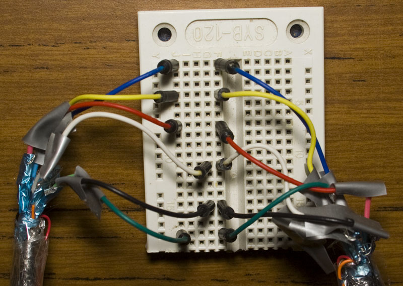
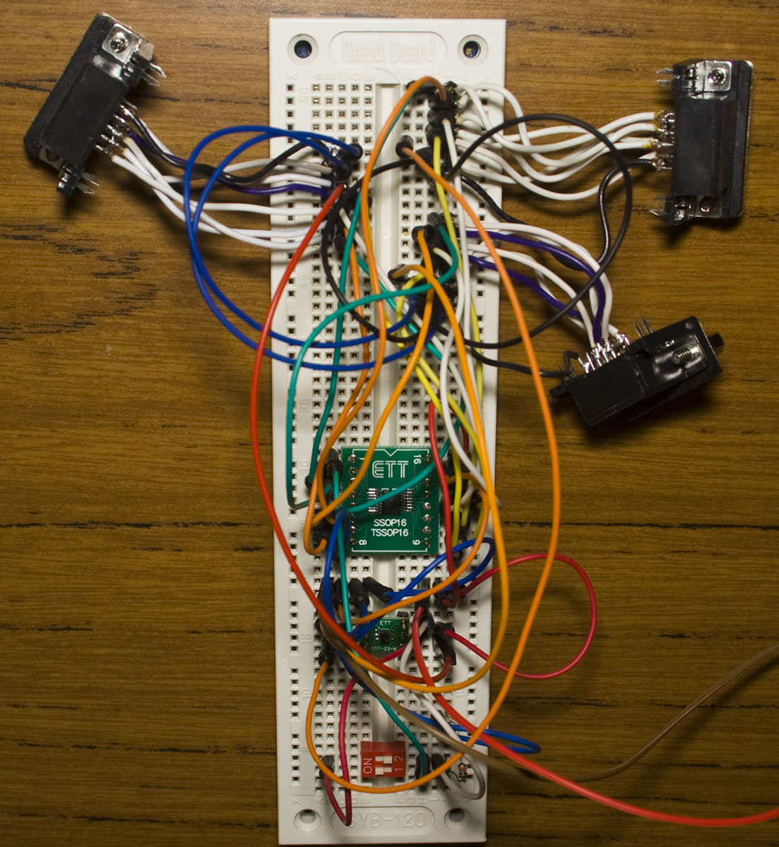
(sneak peak of our prototype in action)
The video side of the KVM will use the VGA, firstly we need to find out how many wires of the VGA we’ll need to pass through.
After slicing some VGA cables, we just need the red, green, blue, hsync and vsync. For each wire, there is a separate ground to it – red ground, blue ground, hsync ground, etc. Firstly I tried connecting all the grounds but noticed some occasional flicker, it’s likely due to the fact that the RGB signals are analog (0.7Vpp) while the H/Vsync are digital and mixing the grounds can cause issues, you normally hear this all the time – separate analog and digital grounds when laying out a PCB. After separating them to RGB and H/Vsync grounds, it works good now.
We need to find an a switch which can pass through the 5 wires we need, have a low on resistance so that our signals aren’t distorted and have enough bandwidth because once you get up to the higher resolutions and faster refresh times the pixel clock (the RGB signals changes) can reach up to 280 MHz.
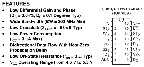
The TI TS5V330 Quad SPDT Wide Bandwidth Video Switch looks like it will do the trick and it’s only $1.2. It has a minimum bandwidth of 300MHz, low on resistance of about 3 ohms but it only has 4 inputs so we’ll need to find an additional switch for the extra 1 signal, I’ll say the vsync one. The good thing about this switch is that there a high impedance mode so we could link multiple of these switches for extra monitors. It operates from 4.5V to 5.5V so we can power it from the first computer’s USB port as we would plug in a USB port to connect in the keyboard/mouse.
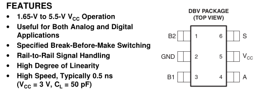
The other switch I’ve chosen is the TI SN74LVC1G3157 SPDT Analog Switch which costs $0.16 and has a typical bandwidth of 300MHz and on resistance of 6 ohms. The only issue is this switch doesn’t have an high impedance mode, but as we are just starting with 2 ports that won’t be an issue. If we need something like a high impedance mode, we could stick a 100K+ resistor on one “B” pins but that would mean we’d need one chip per computer.
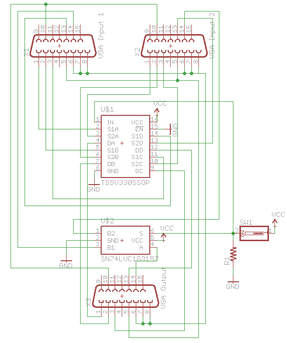
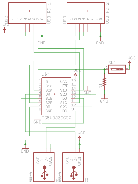
Here’s the schematic, we have the two computer’s VGA ports up the top and the VGA to the monitor down the bottom and there’s just a switch to the IN and S lines for switching displays.
.
USB side
For the USB side, as we’ll be powering our components from the first computers USB port, we should pass this through to the keyboard and mouse. All we’ll need to pass through from the keyboard and mouse to the computers are just the data lines (2 per USB device). I was starting to play around with the idea that a 4066 quad switch could do the job however after a quick test it didn’t work.
I was thinking about using a USB hub chip which would reduce the data lines to just 2 however the prices of the USB hub chips were a bit too much for me, plus they need more external components, so I went back to search for a lower priced switch than the TS5V330 for low bandwidth applications however I couldn’t find any good ones. I re-looked at the TS5V330 it is categorised on TI site as “USB/LAN/Video Switch/MUX/DEMUX” so after giving that a test, it worked for USB. Technically as we are passing the data lines through, you could connect up any USB device – pen drives, hard drives, etc.
There is a problem with passing through the USB, it’s that it will take 2 USB ports at each end, so we would need 2x USB cables for each computer – the price was about $1 each USB cable plus you’ll need to add the 2x USB B ports. I’d like to have just 1 cable, so after looking around a bit, I figure one way to do this is to use an RJ45 connector on the KVM, cut up one end of an existing RJ45 cable and connect that end to 2 USB A ports ($0.2 each). I haven’t received the USB ports yet so I can’t test this out just yet.
Here’s the schematic, RJ45 up the top for each computer and two USB ports for our keyboard and mouse.
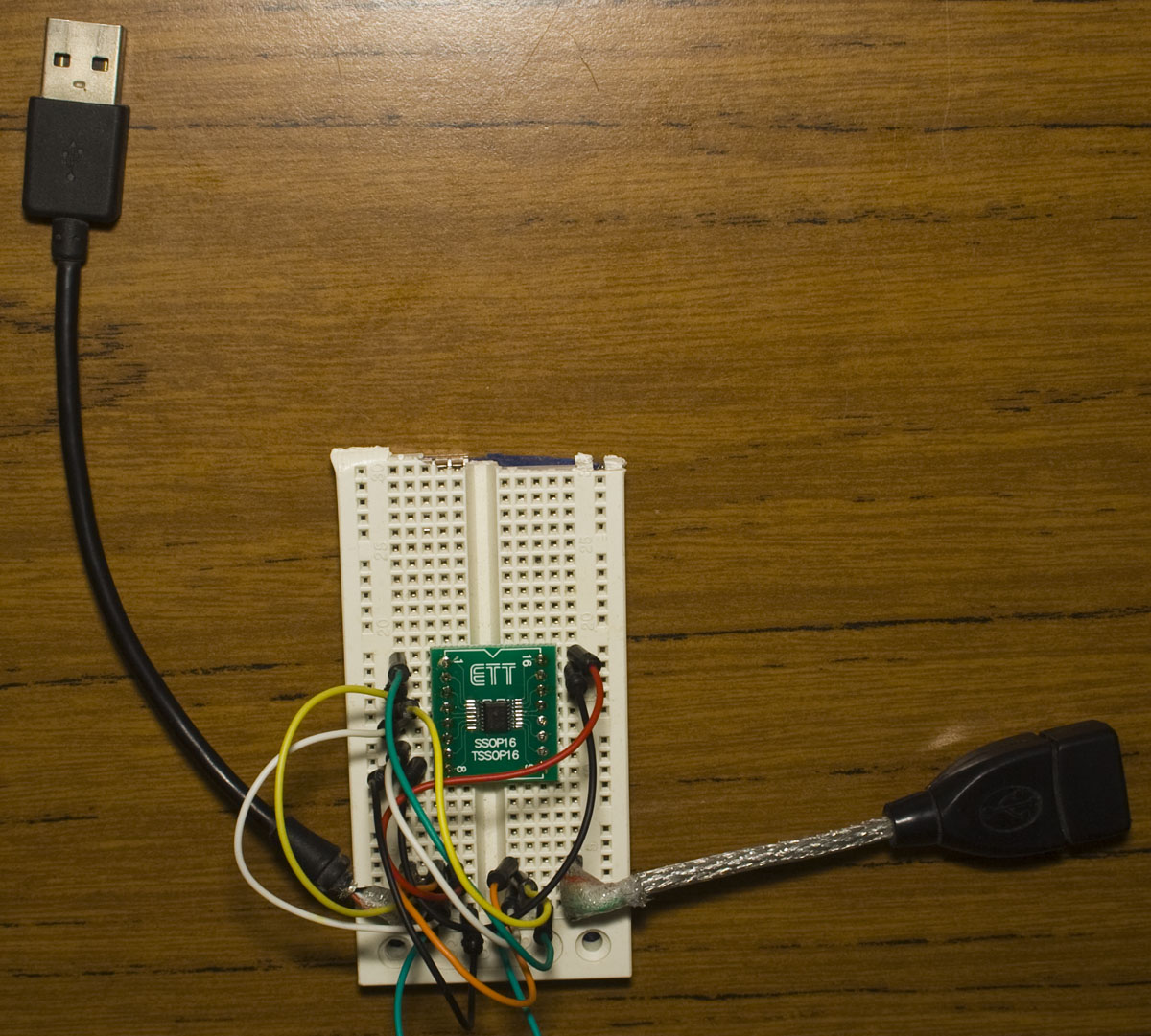
Here’s just the 1 USB connection I tested.
.
Using 7400 series logic for the buttons
I was just using switches for testing but for when we build it up, we’ll be using buttons to select the computer so we need something that can read the button presses. As normal, I was thinking going for an ATtiny however I wanted to explore different options and see if I could reduce the cost too (having a MCU just read buttons and pull lines high seems like a bit of an overkill).
(from Wikipedia)
We need to be able to press a button and have it remember the button we’ve pressed. By using 2 NOR gates in a certain way, we can create a Set Reset Latch (SR latch) which can remember a certain state depending on which NOR gate we apply a voltage to. The 74HC02 quad NOR gate chip is available for $0.2.
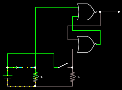
If we push the button on the left, the output goes to 0V and stays there. When we push the button on the right, the output goes to 5V and stays there. We can hook the top output to our “IN” and “S” lines in our switches and could add an LED on each NOR output so we know which computer we’re connected to. At the moment, I don’t have the NOR gates to test this with however when you do power it all up, the start state will be unknown so that could potentially cause a problem.
For the next part, we’ll put it all together on a PCB and see how it performs. I’m thinking about putting the network connector above the VGA connector and on it’s own PCB board to make the single sided boards a bit easier to make.
Building a KVM – Part 1: Selecting switches for video/USB, cabling and using 7400 series logic
Building a KVM – Part 2: PCB Prototype and expanding past 2 KVM ports
Building a KVM – Part 3: Changing to ATtiny24 and PCBs arrived
Building a KVM – Part 4: Expansion board arrived


thanks for the write up. It is pretty good. I will try one myself.
Hello
How many Ohm has the resistor R1 100k? I like build the KVM-Switch for a projekt.
Best regard
Philipp
Hi Philipp, yes 100K or 10K will do.
You should also read part 2, 3 and 4.
https://www.insidegadgets.com/?s=kvm
hay
any chance you could share your eagle library files for the TS5V330 and the SN74lvc1g3157?
Alternatively i could just not be an idiot and download the TI library with them in it.
whoops
Hi there I am trying to create a km switch to use with a Logitech g920 steering wheel to switch between Xbox one and pc is there any simple solutions on how to do this with out using any chip boards?
I am using a breadboard and my theory so far is to use the Xbox one for the power as even when it is not turned on it still powers through the USB ports but would the PC need a full circuit before connecting a device?
Sorry about my questions this is my first time doing something like this.
For a solution without any chips, relays (normally open) would be an option but they can cost $1-2 each, you would need 4 and a SPDT switch to only turn 2 on at a time. The relay would have to be rated to switch on at 5V and the switch would have to handle at least 5V/500mA DC. It would be for the D+ and D- lines, GND would be connected between the Xbox and PC (this can potentially cause a ground loop problem).
e.g
D+ - Relay - PC - Relay - Xbox 5V USB - Switch Pole 1 - PC Relay D+ & Relay D- - Switch Pole 2 - Xbox Relay D+ & Relay D-From your experience with the kvm’s, is it possible to have a usb connected device that relays keyboard and mouse commands to a computer while also presenting attached storage? Essentially a flash storage stick that is also sending keyboard and mouse commands to the attached computer from a wireless networked device.
Looks like you can if it’s a composite device (I haven’t really looked into it) – https://electronics.stackexchange.com/questions/39149/usb-composite-device-driver
Hello,
Works with USB 2.0+? Can I add an audio switch with only one TS5V330?
Thank you!
Hi, I don’t believe it will work work with USB 2.0+ due to the high bandwidth required, the PC might just switch them down to USB 1.1 speeds if it has communication issues. Yes I think you could use one to switch audio signals too.
Hi,
I would like to conform two things
1)will this device work for apple keyboard,and will it support for USB 3.0 device.
2)As you are using RJ45 connector instead of that can we use USB type A connector.
Hi Rahul,
This device should work with any USB 1.1/1.0 device, any 2.0 or 3.0 device may reduce it’self to USB 1.1. I think it should work fine for any keyboards/mice. Yep you could use a USB A connector instead of RJ45, would you just need 2 of them if you want to use 2 ports.
Hello,
Can I connect the pins 5 to 10 (DGND) and connect the pins 6 and 7 to 8 (AGND), using only 2 wires for GND? This would reduce the number of wires to 7.
Hi Axl, yes you can connect pins 5 and 10 as DGND and 6, 7, 8 as AGND, the only downside is it may cause issues if your cable length is long, say a few metres, best to test it out first before making any production units.
Can I remove the SN74LVC1G3157 and use the TS5V330 for both vsync and USB data or you think that SN74LVC1G3157 is better for vsync? Thank you!
Hi, if you have another TS5V330 spare, yep you can use it. I just used the SN74LVC1G3157 because I just needed the extra line and didn’t want to use another TS5V330 just for the 1 line.
Hi, Thank you for the informative web.
One question. In the USB part, why do you connect the VBUS and GND to the VCC and GND, respectively? I mean, the supply rail is supported from the computer so why we need to connect them to another supply voltage.
Can we connect the VBUS (and also GND) of all USBs together?
Many thanks
Hi Mahdiyar,
Maybe I’m missing something but I can confirm that all the VBUS/Vcc are tied together as everything is powered from the first PC, the only exception is that there is no power connected from the 2nd PC to prevent 5V from PC1 from feeding into PC2. This would make the whole thing not work if PC1 is switch off though, you could always use a diode on each PC side if you wanted that or a different circuit.
What is the better way to do this: when you plug the vga/usb cable changes to pc2 automatically, when you unplug the cables it returns to pc1?
You could probably detect a pulse on the H/VSYNC with an ATtiny, Arduino or similar and have that toggle the switch pin.