From our last part we chose the switches to use, the cabling idea to use network cables to connect to USB cables, the 7402 NOR gate to switch between inputs and gave it a test run on the VGA which worked. In this part we’ll put it all together and think about how we can add more input ports to do a 4, 8, 16 port KVM.
(sneak peak of KVM)
The first thing I did was test the 7402 NOR gate to see if there is an oscillation at startup, after a few attempts I found no issues but that you should tie unused gates to ground; even if it started in an unknown state, the state doesn’t change so it’s not too much of a concern for me.
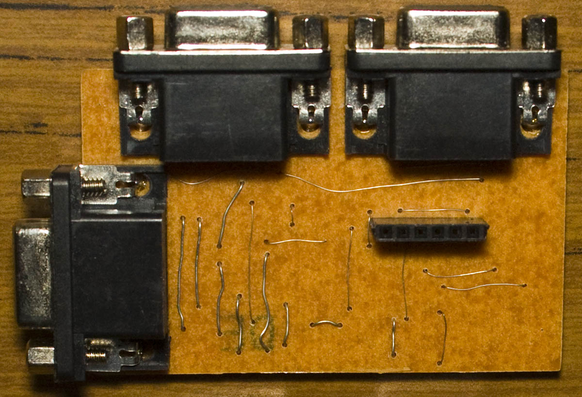
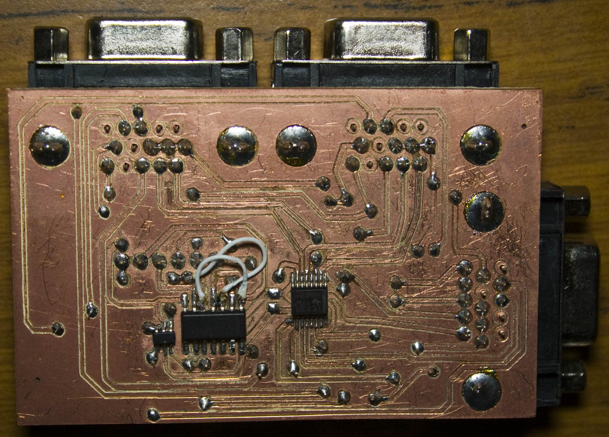
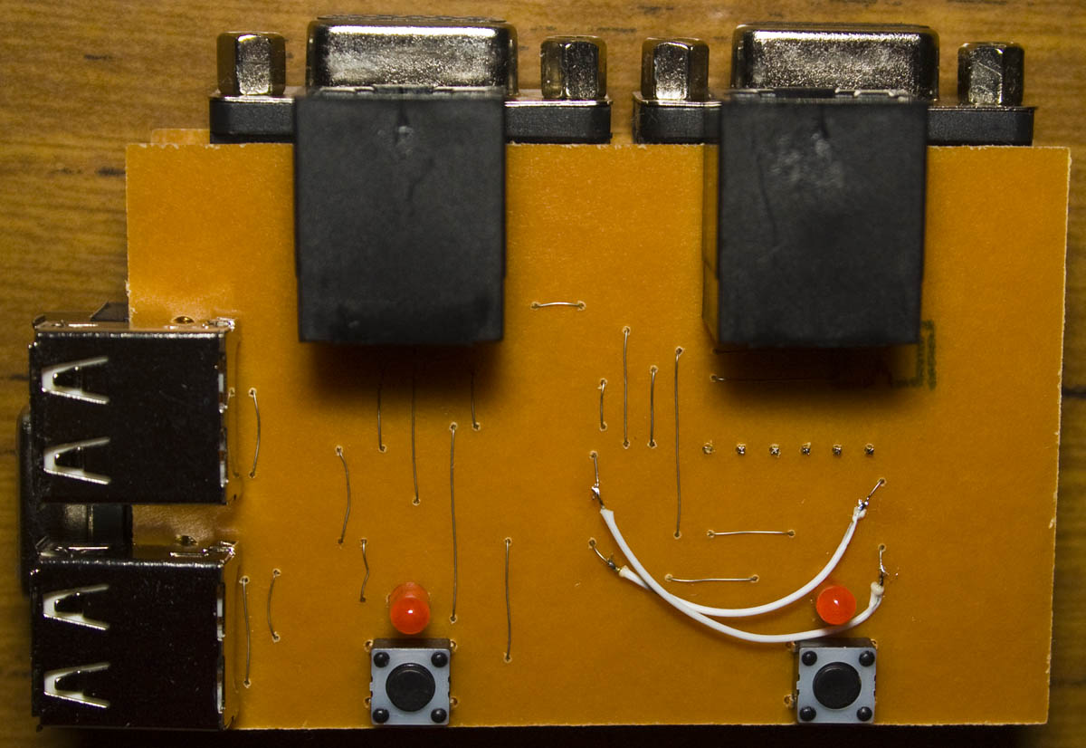
I decided to have the VGA and USB boards separate as it would be easier to route them. The VGA board was built, there was a small mistake with choosing the wrong 7402 part in Eagle so I had to make a few modifications and it tested ok, there is a 6 pin header near the center to connect to the USB board.
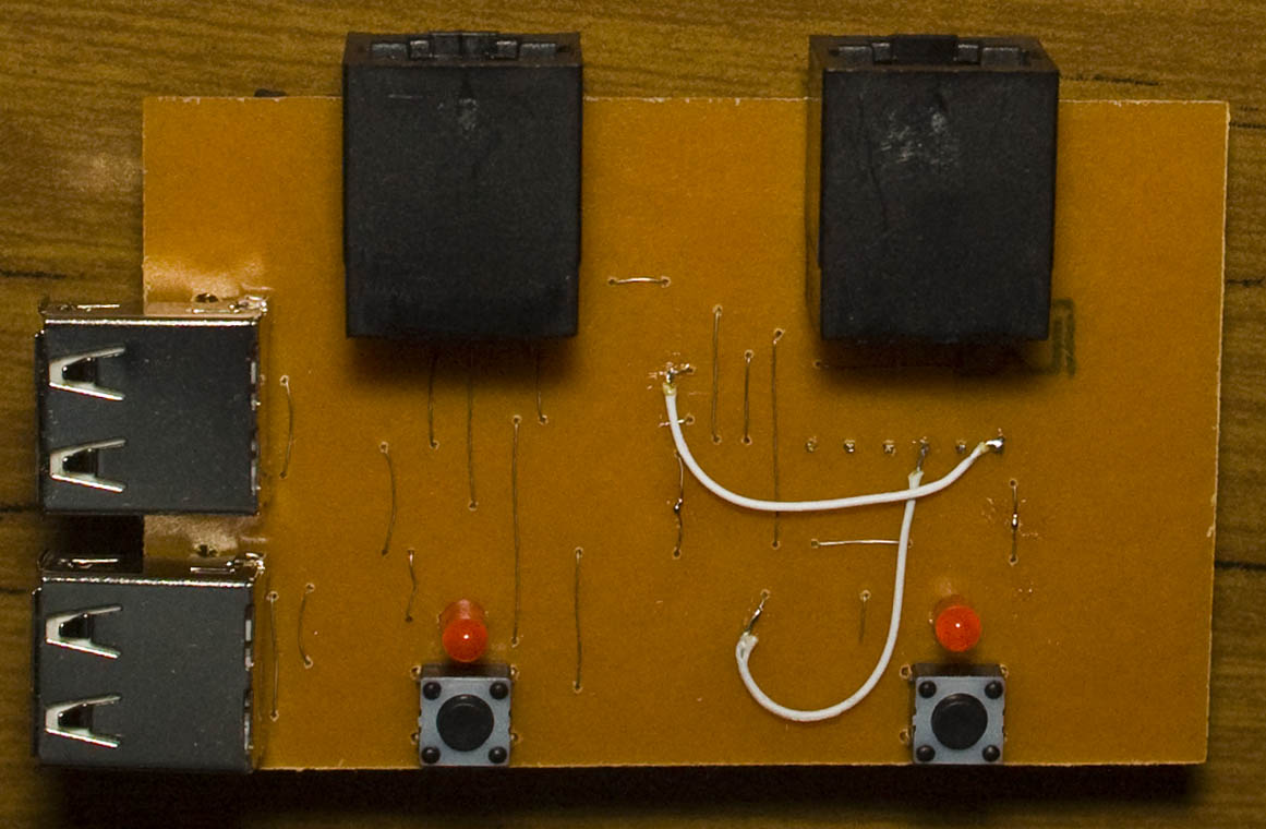
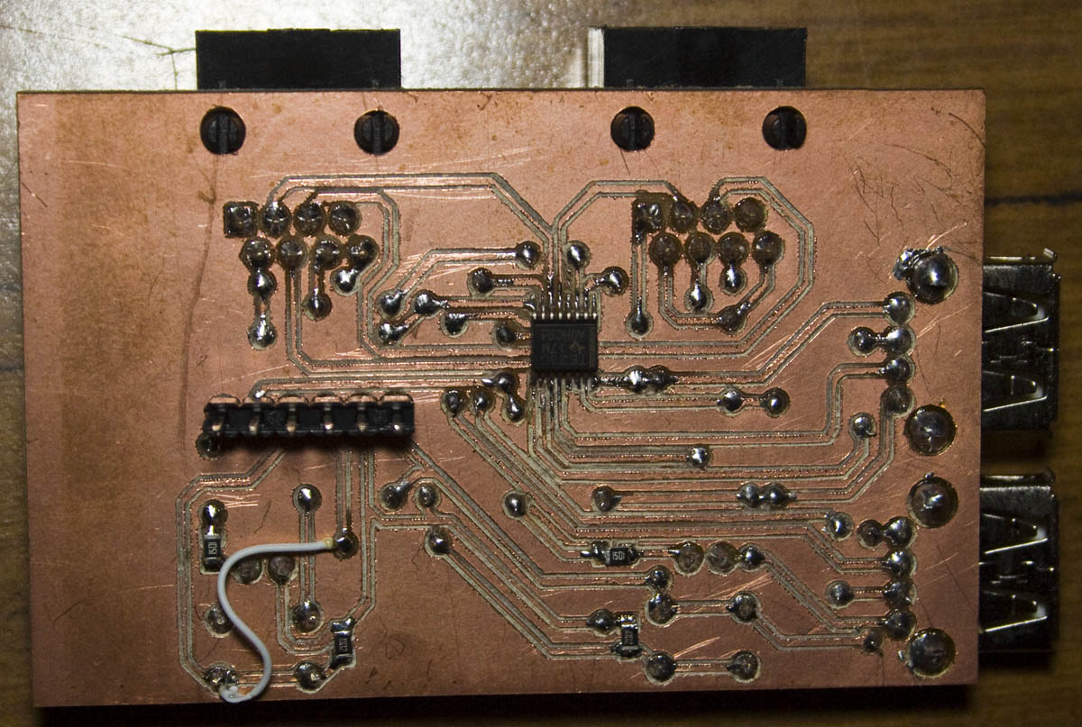
The USB board was next, it contains the LEDs and buttons to switch inputs, there was a few more corrections to make on this board too.
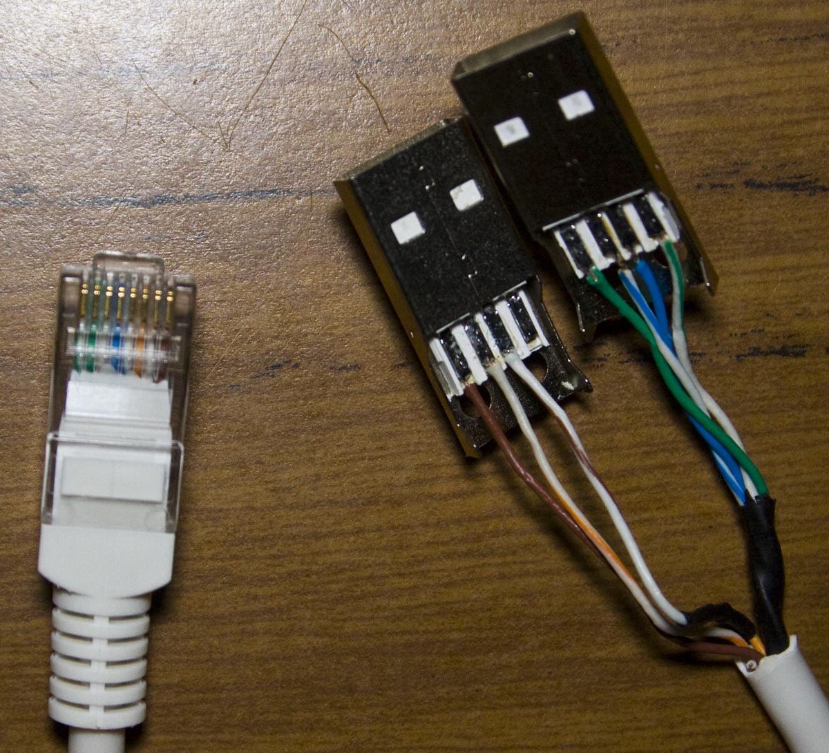
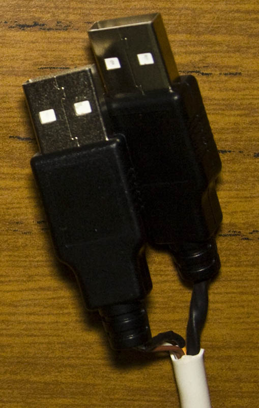
Now we just need to make our Ethernet to USB cables and only the first port / first USB cable supplies 5V to our board. The cables are connected like:
First USB
Gnd = Green		D+ = Blue/White		D- = Blue	Vcc = Green/White

Second USB
Gnd = Brown		D+ = Orange/White	D- = Orange
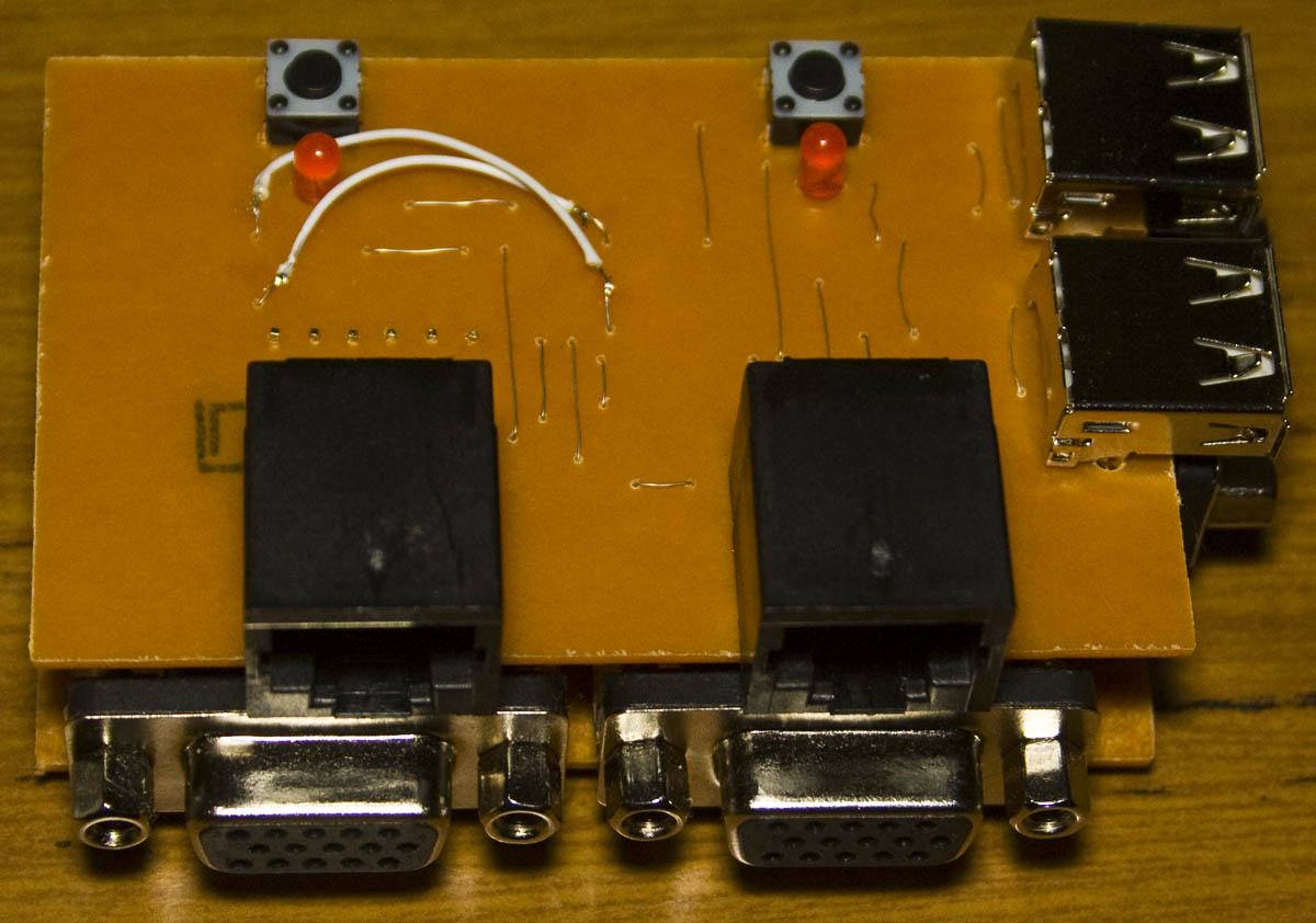
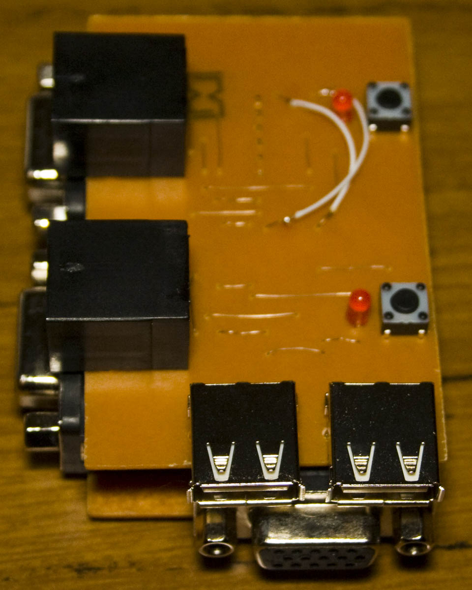
And here we have the end result.
.
Expanding past 2 ports
I’ve been thinking about how we can expand past a 2 port KVM, apart from the analog switches staying the same, it may be worth switching to something else.
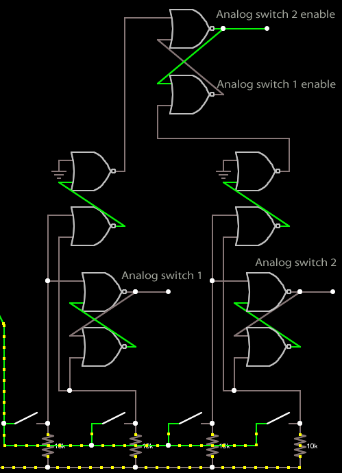
I wanted to experiment continuing using the 7402 NOR gate, we can add 2 NOR gates together to generate an OR gate which goes high when either of the switches are pressed. By doing this on both sides, we can add another SR latch to connect to each OR gate which will be used to select the enable of each analog switch. The solution above works good for a 4 port KVM but for more ports it becomes a bit more complicated.
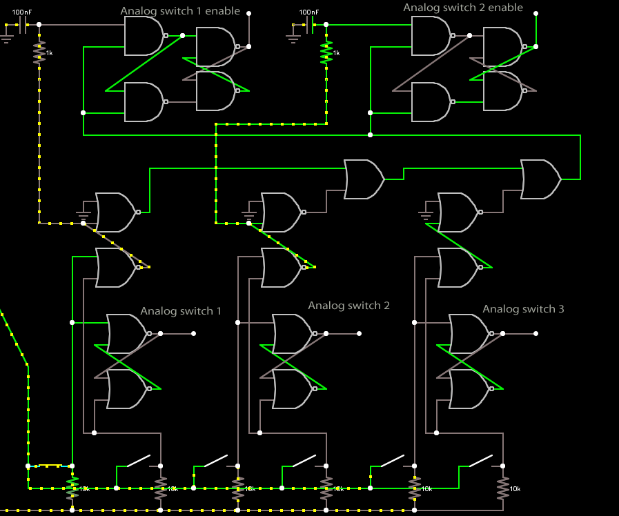
We can use a gated D latch which is an SR latch except that it has a way where it keeps it’s previous state when the enable pin is low. It’s similar to the last diagram except that I have the switches OR gate connect to another OR gate in such a way that if any switch is pressed, all the OR gates work together that it sets the enable pin high in the gated D latch.
In the example above, I’m pushing the first switch and the enable D latch pins all go high. There is a low pass filter to get the D latch operating as I want it in the simulation – the analog switch 1 enable goes low and will stay low when the button is released. We could potentially keep chaining these all up however the downside is that you will need a lot of logic and you’ll also need a terminating connector at the end.
Now for the simple solution – just use an ATtiny25 for 2 ports. We would have 2 pins monitoring each button, 1 pin for the enable and another pin protected by a resistor which would connect to all other ATtinys which would monitor if it goes high, if so it tri-states the analog switches. If a button is pressed, it switches that pin to an output and pulses it high for a little bit and sets the enable for the analog switches. Edit: Looks like I might need a shift register or a higher pin count ATtiny to connect all the pins – 1 enable, 1 analog switch in, 2 for each small analog switches, 2 LEDs and 2 buttons.
To connect the boards I would need about a 15 pin interconnect, it would just be on a single board and may need to use some screws/nuts and a small piece of metal to join the KVM boards together more securely. I should also put a 500mA polyfuse on the 5V supply but that’s it for the time being until I decide to put this into production.
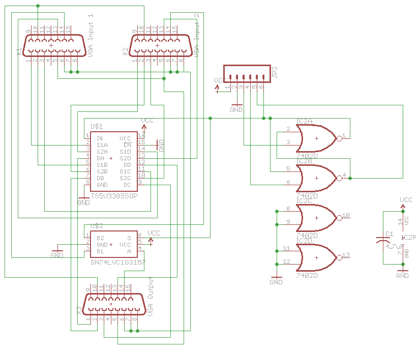
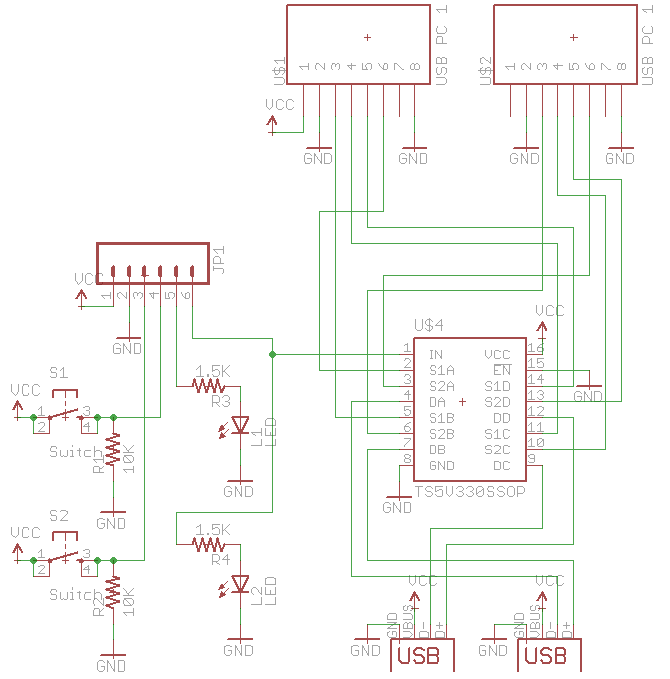
Here’s the schematics of the KVM VGA and USB board with the fixes I’ve made. Download KVM_v1.1
Building a KVM – Part 1: Selecting switches for video/USB, cabling and using 7400 series logic
Building a KVM – Part 2: PCB Prototype and expanding past 2 KVM ports
Building a KVM – Part 3: Changing to ATtiny24 and PCBs arrived
Building a KVM – Part 4: Expansion board arrived


Does this version (without expansion, KVM_v1.1) works perfectly or does it need to do some modification?
Hi Celso, yes this version will work fine, it doesn’t have the option to use an expansion board. You will need to build the bottom and top boards for it to work (unless you modify it). Take a look at the project page if you want a proper PCB for it.