From our previous post, we made our prototyped PCBs which all worked together well. This time we just have a quick update – we’re making a few changes along with building acrylic cases/mounts for some of our boards.
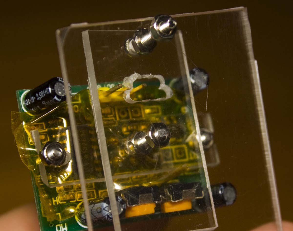
I’ve been rethinking my idea about using the existing plastic casing for the PIR, since I intended this to be a standalone alarm system I should really make my own case. We’ll need a way to mount the PIR sensor at an angle to the wall to point a bit downwards otherwise it’ll just point straight on and may not cover the whole room. Initially I started with the design above, there’s quite a bit of acrylic boards all screwed together with M2 screws.
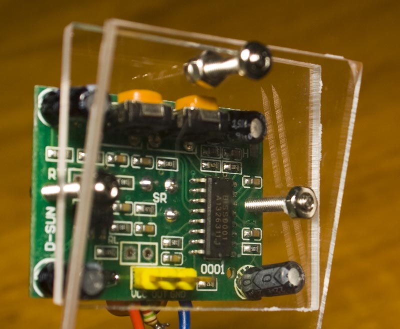
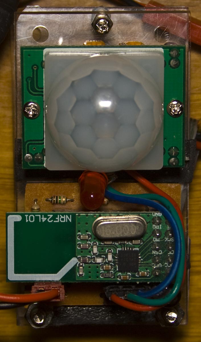
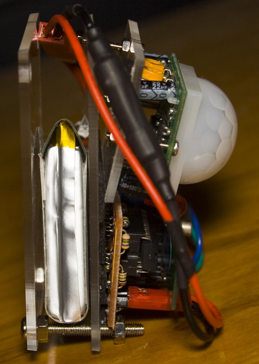
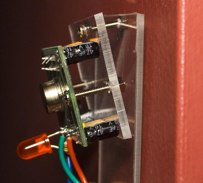
I went for a re-design and now it’s looking better with less parts being used. I’ll need to add some mounts to the ATtiny84 PIR PCB, switch the M3 screws that hold the Lipo in place with longer M2 screws and then add a small hole at the top so I can nail the bottom board to the wall and that will sort out the PIRs.
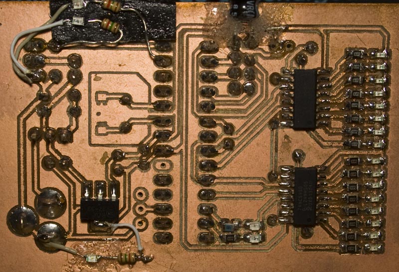
I’ve just added an extra 2 LEDs to the server, one to say that the system is armed, one for the siren and another to show that power is ok, something I should have done from the start.
While testing the door sensor with an external supply I found that the resistor divider feeding into the ATtiny’s ADC was jumping around quite a bit but when I ran from the battery it worked fine. As I already had made the PCBs, I added a 0.1uF capacitor and that sorted it all out.
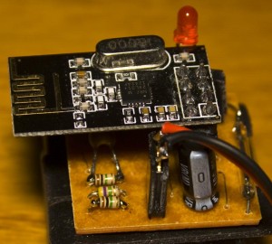
I also received the CR1220 holders from Ebay and all is good with the remote. Apart from those couple of changes and building the cases, there isn’t much else to report other than I’m slowly working to the end result.


