With all of the recent GBC/GBA LCD upgrades available, it made me interested to learn more about LCDs and the signals to make them work, a subject which I hadn’t explored before thinking it might be a bit complex. Let’s take a look at the 40 pin GBA LCD and how we can change certain signals using a CPLD.
(Sneak peak)
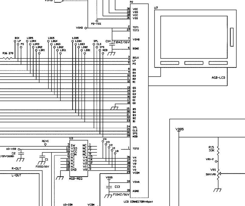
Firstly, we’ll take a look at the GBA schematic which shows the LCD screen and all the connections going to it. It looks to have a fair few voltages required by the 40 pin LCD supplied by the AGB-REG chip while the 32 pin LCD on more recent GBA don’t require these voltages and thus don’t require the regulator chip.
We have signals DCLK, LP, PS, R1-R5, G0-G5, B1-B5, SPL, CLS, SPS and MOD but what do they do? For that we’re going to have to get the logic analyser out! Before we do, just by the naming, we can tell that we’ve got Red (R1-R5), Green (G0-G5) and Blue (B1-B5) so it’s 16 bits but since G0 is grounded we have 15 bits of colour.
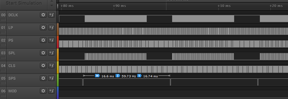
Here’s how it all looks zoomed out a bit. We can see that the SPS signal has a duty cycle of 59.73Hz which is the screen refresh rate on the GBA.
Previously we made a SNES transmitter board which allows you to converter your SNES controller to a wireless controller and allow you to use any of the existing receivers we have available.
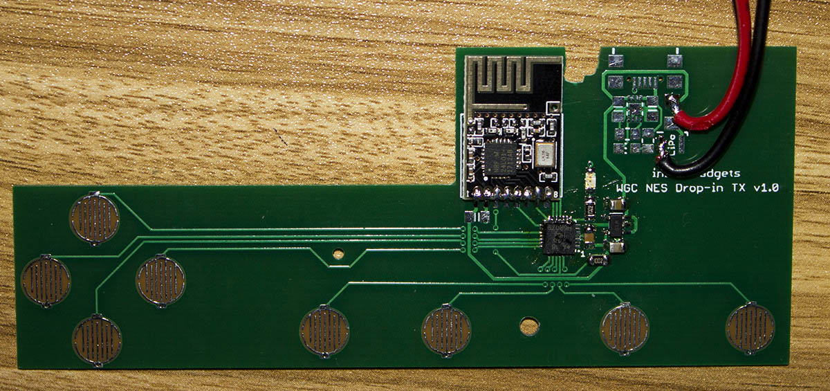
Today we’ll look at making an NES drop in board for the generic NES controllers you can buy off Ebay and also revisit the GBA TX cart’s CPLD code after I made a basic 32MB GBA cart so we can remove the 50 MHz oscillator.
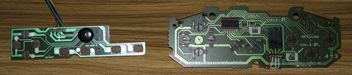
It seemed like a good starting point for the drop-in boards as the existing board shape is pretty simple where as the SNES board shape is a bit more complex.
(sneak peak, new boards will be ordered)
We can pretty much re-use all the components we used on the SNES TX mod board for this NES drop in board. Now that we’ll have control of the buttons ourselves we don’t have any chip that we need to switch on with a P mosfet and thus our power consumption when sleeping and power on response when the start button is pressed will be improved.
The only thing I hadn’t done before was making button pads on the PCB before. I looked around for existing Eagle libraries that had them but only found one which was pretty small. There are lots of different designs out there, some like the SNES have carbon coated pads on the PCB and others just have the bare PCB exposed.
Previously we added NES, WiiMote, N64 receivers and a Multi-RX Adapter for the Wireless Gameboy Controller. I think that pretty much covers all the receivers for now so I thought the next stage, while not related to the Gameboy directly, is to add transmitter sides to the receivers for NES, SNES, GC and N64.
Today we’ll look at the SNES transmitter board.
(sneak peak)
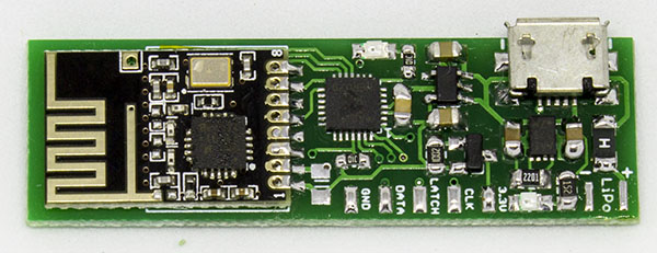
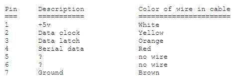
I want it to be as simple as possible to install, not like some others where you might have to wire up each button to the board, instead make it just query the SNES controller like a SNES console would. It would be neat to make an actual drop in replacement PCB – maybe something for the future. For the moment, it would mean just 5 wires to hook (Vcc, Gnd, clock, latch, data) up plus the LiPo battery, speaking of which, we’ll put a LiPo charger on the board. For the MCU, I went with the cheapest and smallest option I have used before, the ATtiny48 which can run at 8MHz. As you can see by the PCB design, I tried to make it pretty compact and not too wide which worked out quite well.
Upon testing a SNES’s controllers current consumption it’s a few mA so we can’t just leave out the SNES controller running all the time. We can choose to have a switch to turn everything on or off or just use a P mosfet instead – to keep things as nice as possible with minimal cut outs, I went with the P mosfet. But now we have to consider how to wake up, should we wire up to one button or can we do something else?
Previously we made the GBA TX Cart for the Wireless Gameboy Controller so now it’s time to keep adding more receivers to the project. We have the NES, WiiMote (which should also support the NES/SNES Classic Mini), the N64 plus a Multi-RX adapter which allows you to switch out systems for a lower overall cost.
NES receiver
As I didn’t have an NES to actually test with, I previously had purchased a Mayflash NES/SNES to WiiMote adapter so I should be able to use that to make sure it works correctly.
As the NES just uses 8 clocks instead of the SNES 16 clocks that’s pretty much all that needed to change. A quick verification and test and it was all ready to go, I had even named the PCB “NES/SNES RX” before hand.
WiiMote receiver
Since I had the Mayflash WiiMote adapter as mentioned, I started looking at it with the logic analyser whilst reviewing different websites to verify their data against what I was seeing with the logic analyser; in some parts they were correct and in other parts they were slightly off.
I won’t bore you with the details but I did get pretty far into it with an ATtiny, up to the point where everything was sent/received in the clear but then it came to the encryption stage. I thought perhaps if I don’t reply to those encryption requests, etc, it may bypass the need but it didn’t seem to be the case so that’s when I decided it was time to look to see if someone had released some code for that.
Previously we made a Super Nintendo receiver for the Wireless Gameboy Controller but it would nice to add L & R support so that some games on the SNES could also be playable and it would also allow GBA games to be played which used the L & R buttons so that’s what we’ll do, make a GBA TX cart.
(sneak peak)
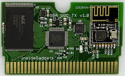
One of the problems is the GBA carts size, it’s half the size of the Gameboy cart so we don’t have a lot of room to work with and we need to fit a CPLD, flash chip, AVR MCU and the nRF24L01+. After a bit of browsing around trying to find the smallest CPLD & MCU, I came back to the Altera 5M80Z which I was looking at for a flash cart but didn’t go ahead with it due to the 0.4mm pin pitch but it’s basically the only choice.
For the AVR MCU, it doesn’t need a whole lot of I/O or anything special, so I settled with the lowest cost one, the ATtiny48. It runs at 8MHz max so it isn’t that fast and doesn’t have an option for an external crystal. I suspect that even if it could run at 16/20MHz it may not be fast enough for detecting data from the GBA so what I decided to do instead was have the CPLD communicate to the ATtiny48 directly; once data was ready it could potentially just set a pin high and then read out the data whenever it wants.
We didn’t need a CPLD with the Gameboy TX cart but we’ll need one for the GBA due to the way the GBA uses all 24 pins to set the address then latches the lower 16 bits of the address by setting CE low and it uses the lower 16 pins to read/write 16 bits of data. There is a way to increment the lower 16 bits by pulsing the RD pin which is also used. In some ways it’s easier than having to make an MBC like on flash carts.
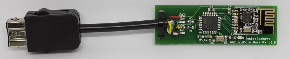
Previously we made a Gamecube receiver which plugged into the Gamecube port which allows you to play Gamecube games, GameBoy games via the Game Boy Player or play Wii Virtual Console or Gamecube games via the Gameboy wirelessly. A few users requested a Super Nintendo receiver which should also work with the GBA Consolizer project, so let’s take a look.
A quick look at the SNES pin out shows that there are 3 lines – clock, latch and data so this should be relatively simple.
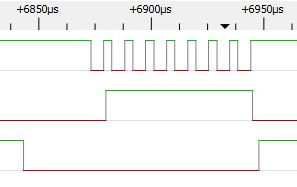
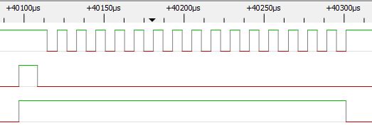
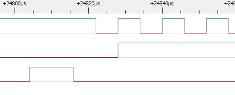
Out with the logic analyser we go, we can see the latch, 16 clocks (clock polarity is low) and the data is high by default. When a key is pressed the data bit for that clock cycle goes low.
For example if the B button is held down it appears on the first clock cycle, we can see that the data line is low until the clock goes high again.
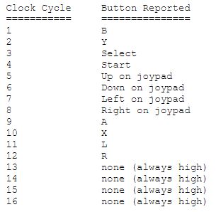
We also have a listing of which clock cycle corresponds to which button is pressed.
Since making the the Wireless Gameboy Controller, there were some ideas thrown around about making other devices of it wireless, one of them was the Gameboy Link Cable which we’re going to look at today.
(sneak peak)
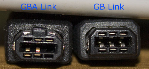
There are different link cables – one for the Gameboy and another for the GBA. I ordered both but only the Gameboy link cable had all the pins on the connector where as the GBA only had the ones it needed. The GBA connector won’t fit in the Gameboy but the Gameboy connector will fit into the GBA.
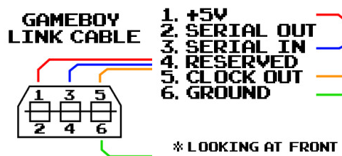
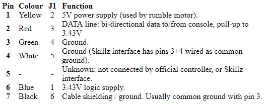
Let’s take a look at the link cable pinout. We have 5V, serial out, serial in, clock out and ground, seems easy enough.
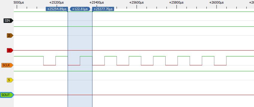
Out comes the logic analyser to take a look at the signals, the game I was trying the multiplayer on was F1 Race and with just 1 end of the cable connected. We can see the clock is slow (120us per cycle) and that the serial in is high, serial out is low so it doesn’t seem to be sending anything. The F1 Race game shows that you are the only player in the game and you can continue on to the race.
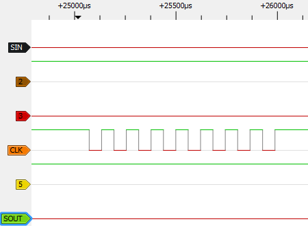
When the other side is plugged in, we can see the SIN goes low. F1 Race now waits on the screen like we are waiting for other players.
Previously we were able to use 2 carts to communicate to each other to play Pong with a little mod and some code changes. This time as per some users request, we’ll be taking a look at adding a Gamecube receiver which will emulate a Gamecube controller. This could be useful if you wanted to play Gameboy games on the Game Boy Player or the Virtual Console / GC mode on the Wii.
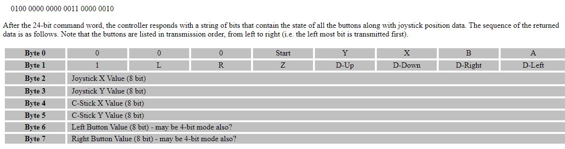
After a quick check on what was out there already about the Gamecube controller interface, I came across the int03 site which gives us the controller pin out and that it’s a serial interface which is held high to 3.4V and is pulled low.
It looks like the Gamecube polls the controller which replies back with the button presses however the website mentioned that at first the Gamecube sends eight 0’s but they don’t appear to have the communication after that, how they reach the Gamecube requesting the controller state.
It looks like we’ll have to capture the initial communication with a logic analyser and also re-confirm their findings so I took apart my Gamecube controller and wired it up to take a look.
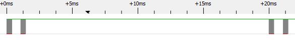
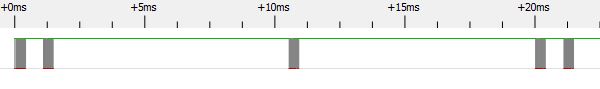
Firstly it seems like the Gamecube polls the controller at varying polling times, it may depend on whether you are in the system menu or could possibly depend on the game. We have a poll then 1ms later another poll which might be for debouncing and then 19ms after we have another 2 polls. On another instance we have the first two polls then a poll after 9ms and then the other 2 afterwards.
The first thing we need to figure out is how we will get ATmega to output data to the Gameboy because at the moment we’re currently using the ATmega to read what the Gameboy puts on the address/data lines. If we tried to read from anything at the moment, the flash chip would be the device outputting data.
What if we cut the A15 line going into the flash chip’s CE line and change it to A14? This means that anything from 0x0000 to 0x3FFF will set the CE line active but then anything from 0x4000 to 0x7FFF will set it not active. This means that nothing will be outputting data if the Gameboy requests it, so if the ATmega can respond quickly enough, it could output data and the Gameboy would pick it up. But by doing this we are limiting ourselves to 16KB ROM size.
One problem is that the flash chip I chose uses the 0x5555 flash instructions which means we do need A15 to go to CE when flashing the chip. Not too much of an issue, I just wired up a DPDT switch for that purpose.
LD (0x7000), a
NOP
NOP
NOP

; Read data
LD E,(HL)
Let’s try to read data to see what it might look like with a logic analyser. We’ll write some data first and then try to read data.
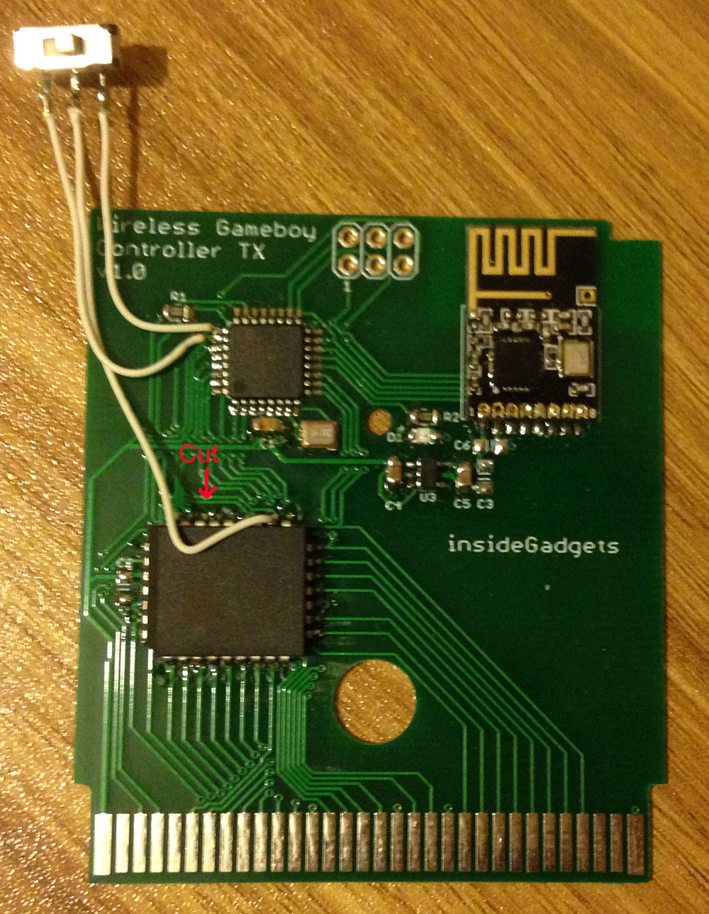
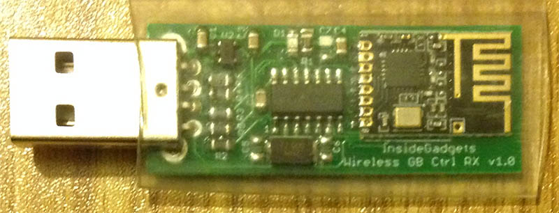
Previously we put together a Wireless Gameboy Controller using an ATmega to read the key press data which the Gameboy sent at a special address and then it was transmitted via an nRF24L01 to a USB device acting as a HID Joystick controller.
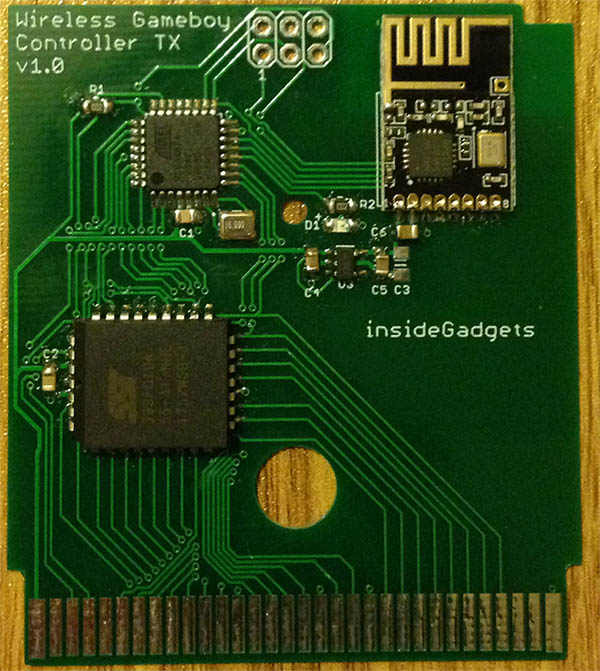
Everything worked nicely so I laid out the cartridge and USB receiver boards, sent it off, received the prototypes.
The cartridge worked first go however when putting on the top half of the case, it was a tight squeeze and was difficult to remove because the nRF module was blocking it’s path, so for the final board I’ll have to move it down a little.
For the USB receiver, I ended up getting the nRF DO/DI pin mixed up so random data was being received. Not to worry though, I recalled that the ATtiny841 swapped the DO/DI pins for whatever reason compared to the ATtiny84. I soldered on the ATtiny841 and it all worked fine too. I’ll put some clear heat shrink over it once testing is complete.
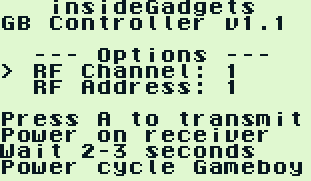
Adding nRF24 Channel/Address configuration
I wanted to add a method of changing and saving the nRF channel/address to the ATmega’s EEPROM so I made the GB program detect if the start button is being held down to boot into the configuration menu. We can now adjust our channel or address, this could be useful if you had multiple receivers and wanted them all to have the same address/channel or if you had some Wifi interference.
if ((readAddr & 0x1F) == 0x06) { // 0x6000 and WR low
	nrfChannel = readData;
}
// RF Address (second stage)
else if ((readAddr & 0x1F) == 0x05) { // Address 0x5000 and WR low
	PORTB |= (1<<LED);
	nrfTx[4] = readData;

	// Update our EEPROM
	eeprom_write_byte((uint8_t*) nrfChannelLocation, nrfChannel);
	eeprom_write_byte((uint8_t*) nrfTxLocation, nrfTx[4]);

	// Update the nRF settings to transmit the data to the RX
	mirf_config_setting_update();

	// Transmit the nrf setting to the receiver until powered off
	dataOut[0] = nrfChannel;
	dataOut[1] = nrfTx[4];
	while (1) {
		mirf_transmit_data(2);
		_delay_ms(50);
	}

	PORTB &= ~(1<<LED);
}
For saving this configuration to the EEPROM we need to choose a different address than 0x7000 which is used for our key presses, I went with 0x5000 for the channel and 0x6000 for the address (of which we only store the last byte of it).
AdvanceVGA – Play your GBA on the big screen! Swap out the LCD for our board, solder some wires, connect 5V USB and VGA and you’re ready to go.
GBxCart RW allows you to backup GB/GBC/GBA ROMs, save or restore game saves and re-write supported flash carts. Mini RW option available for GB/GBC only.
Wireless Gameboy Controller – Use your Gameboy, mGB, GBC, GBA, GBA SP, GB Micro, NDS and NDS Lite as a wireless controller on Windows, Linux, Raspberry Pi, etc, and on your NES, SNES, N64, Gamecube and Wii.