Posted in Teardowns on Mar 3rd, 2019
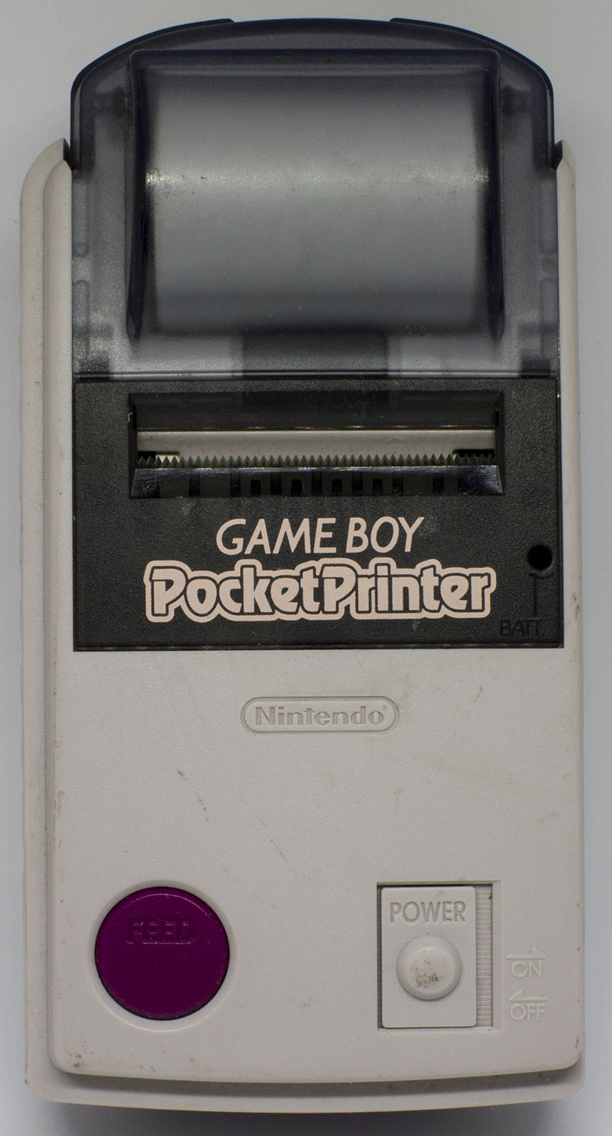
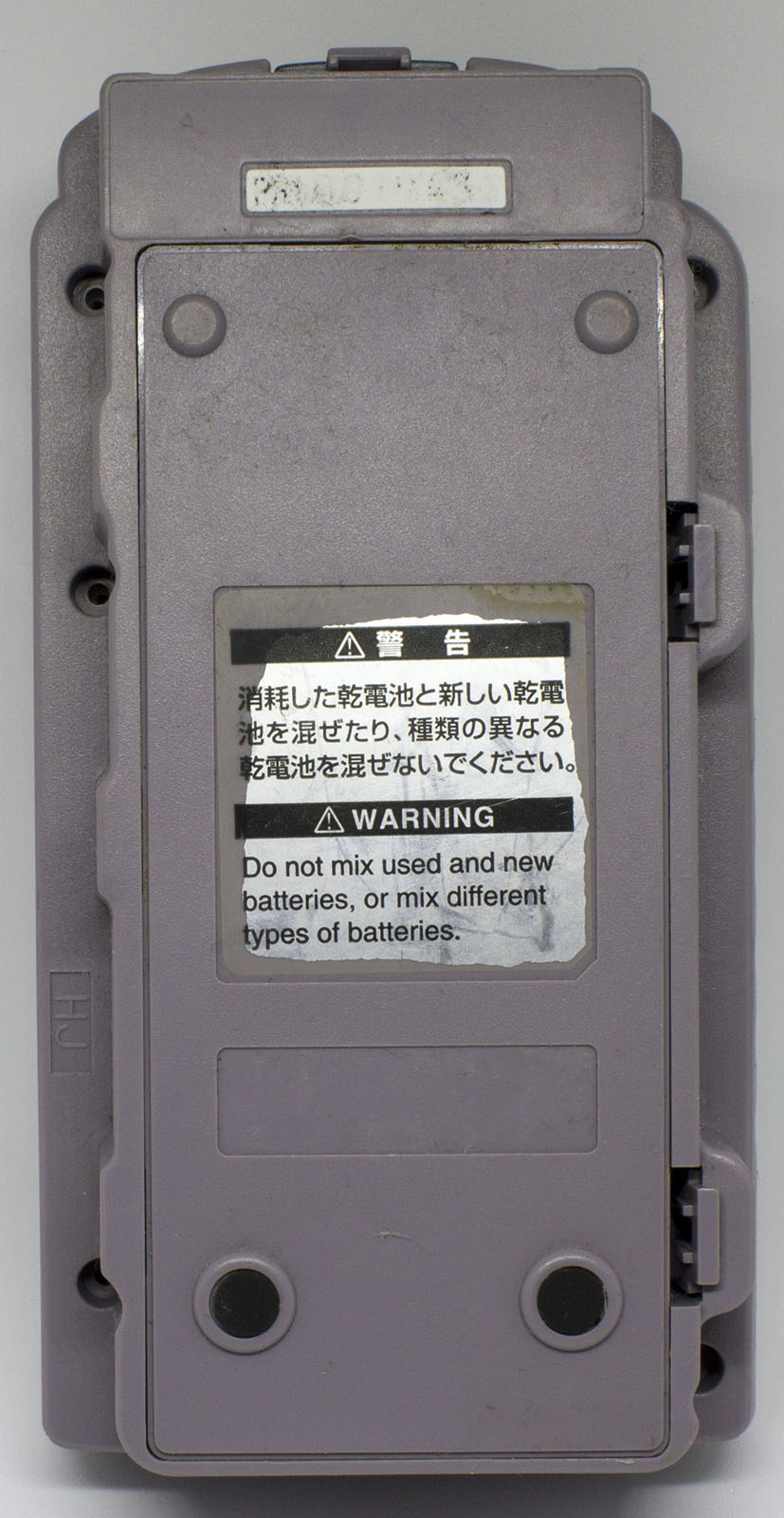
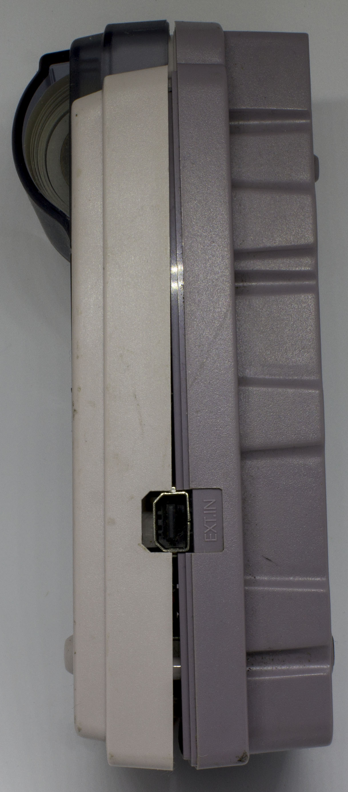
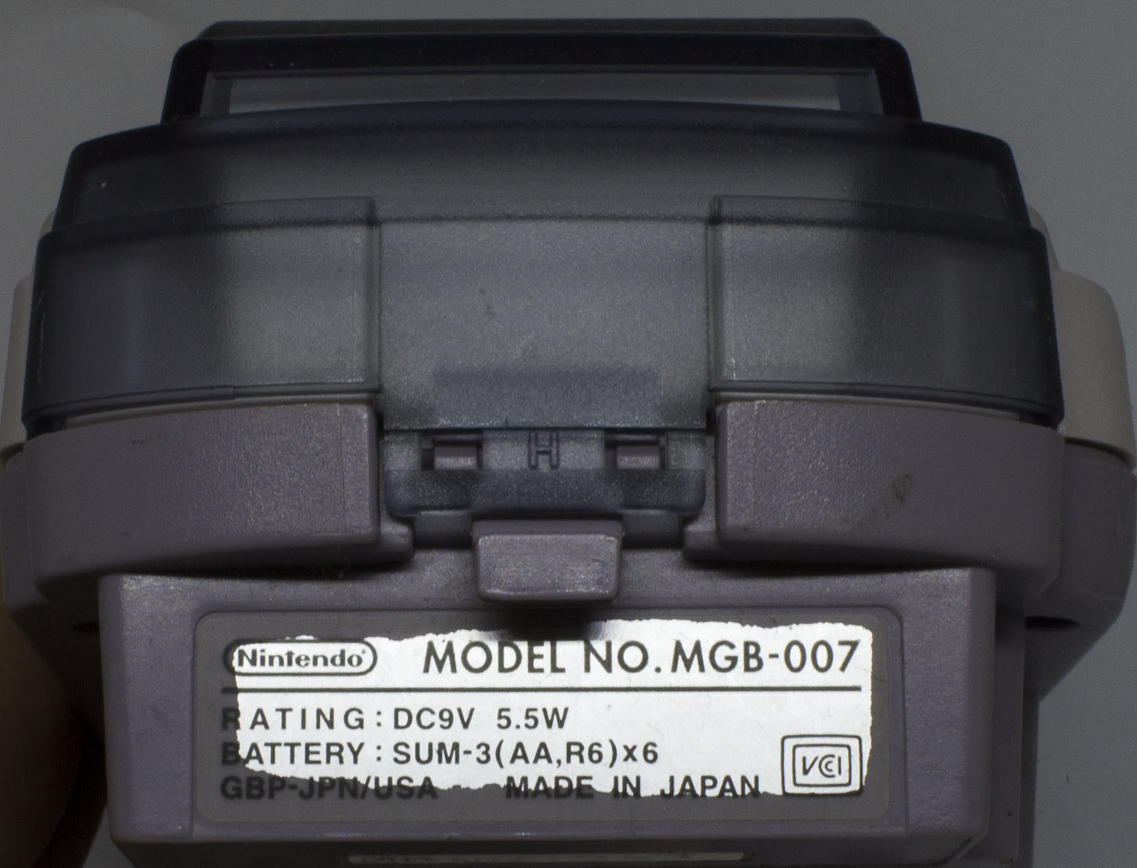
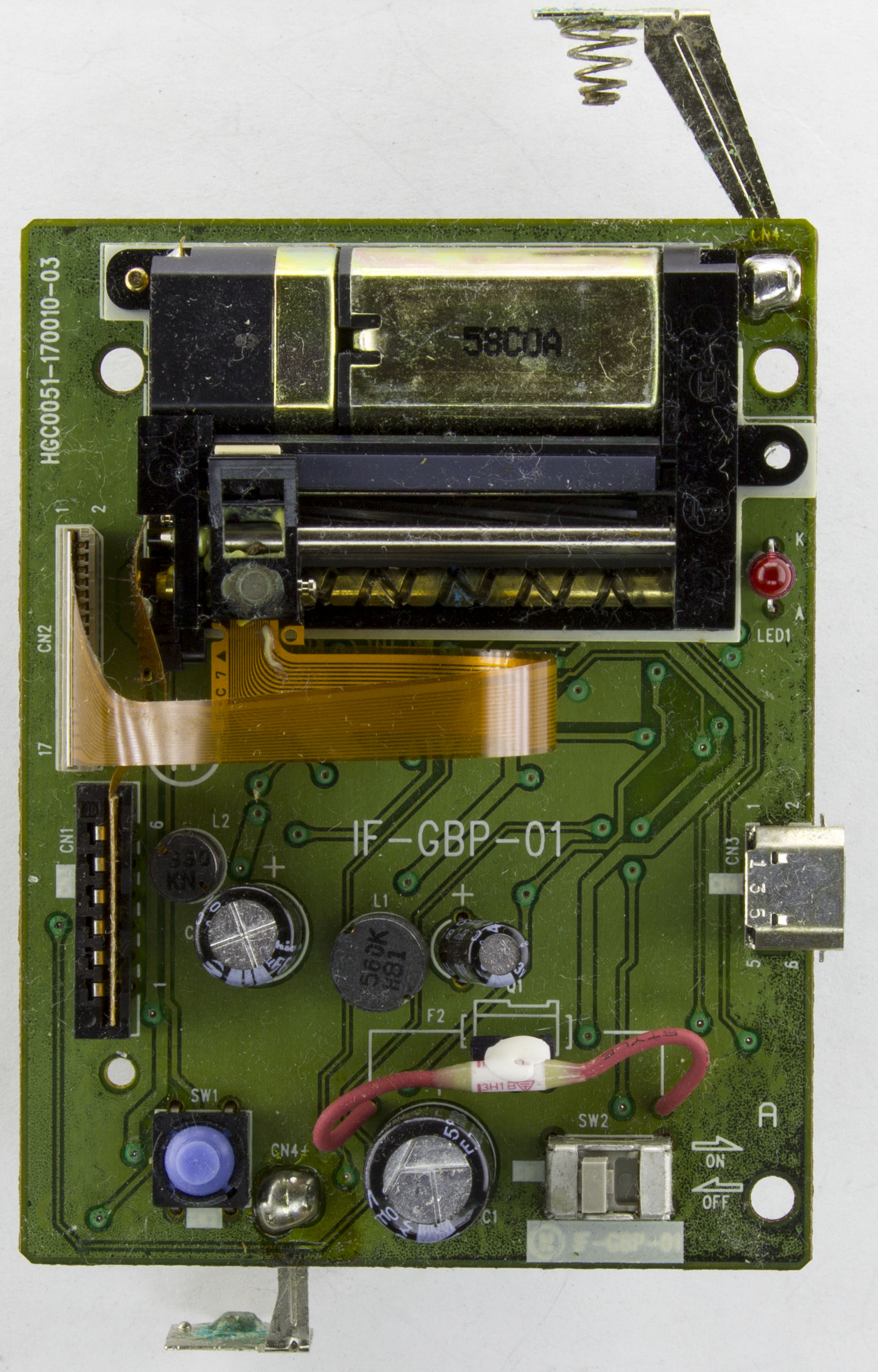
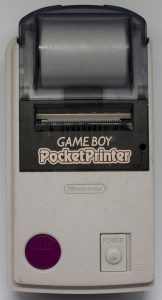
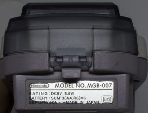
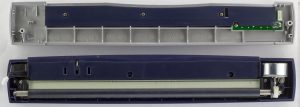
Keeping up with the recent Game Boy related posts, today we’ll be taking a look at the Game Boy Pocket Printer (MGB-007) which connects to the Game Boy via the link cable and is powered by 6x AA’s.
A few screws later and we’re in.

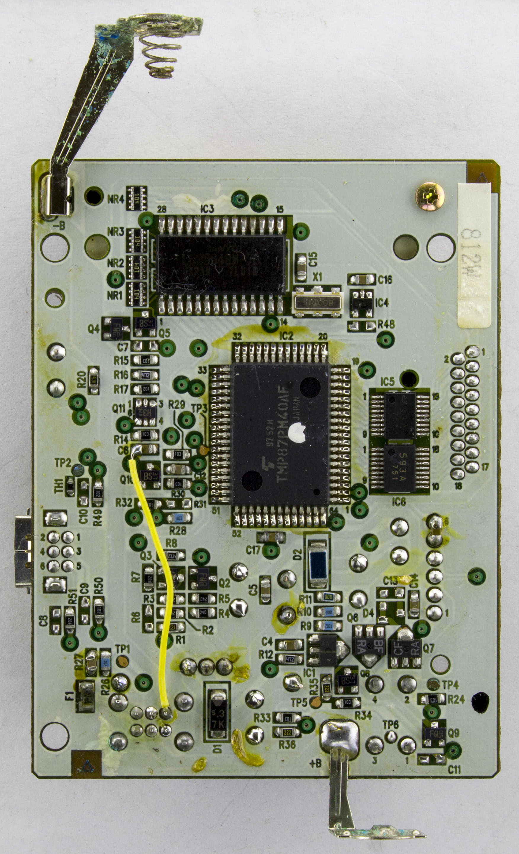
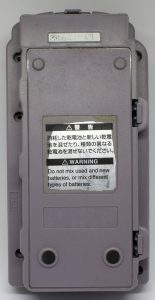
The thermal print head/motor assembly looks very similar to the one used in the Thermodrucker Printer. Capacitors are decent branded Sanyo/Nichicon ones. On the back, we have ourselves a bodge wire. The battery terminals are starting to corrode. At first it looks like all the vias have corroded but on closer inspection, it’s a green via tent, couldn’t be corrosion as there is a pad named “TP1” which is bare copper and that’s looking fine. There is some weird solder mask corrosion/fading starting on the edges of the board.
(more…)
Read Full Post »
Posted in Teardowns on Jul 28th, 2018
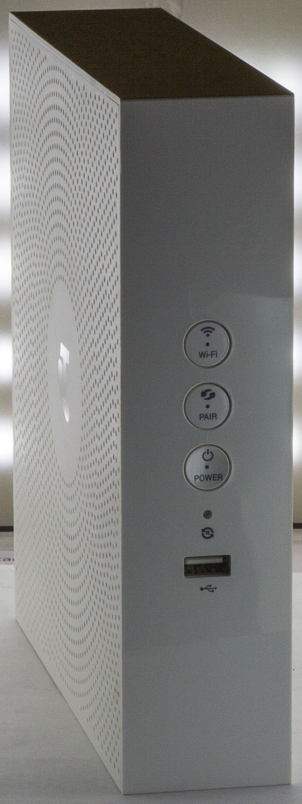
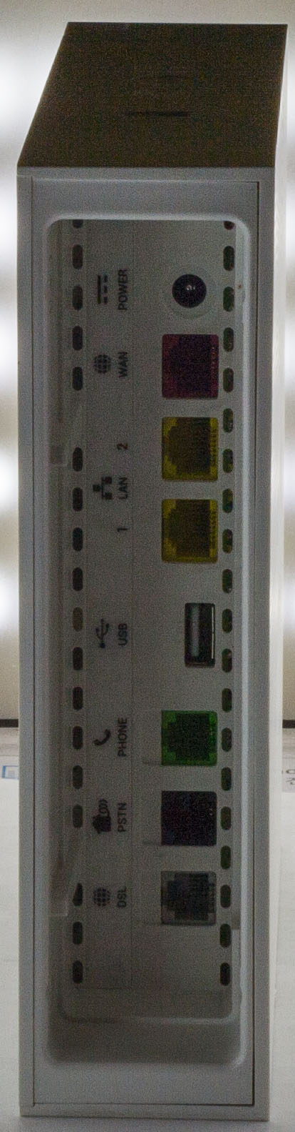
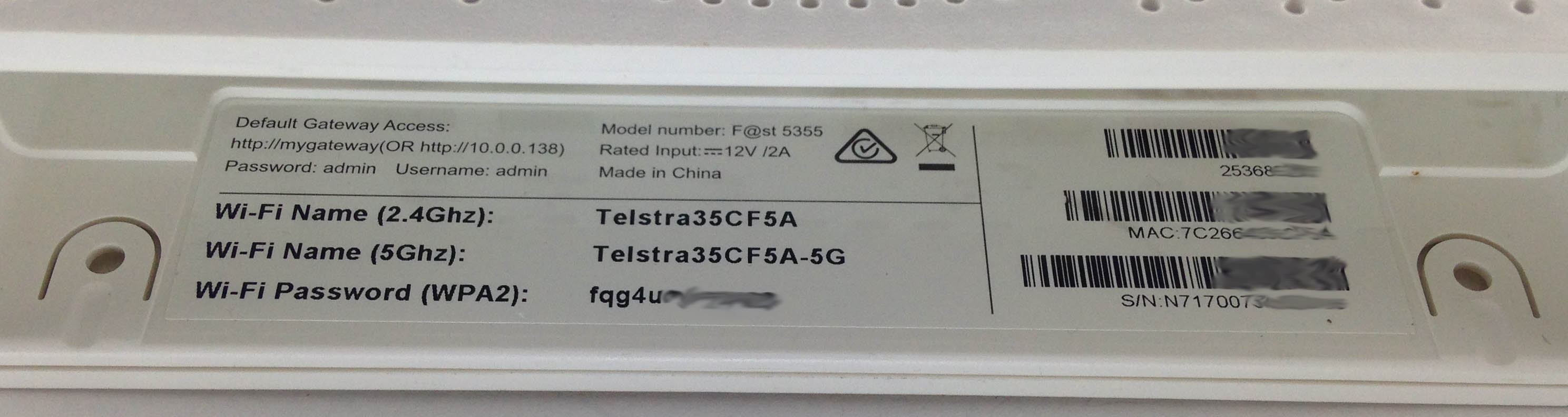
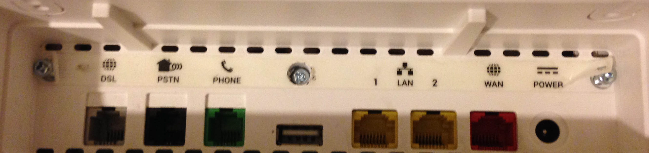
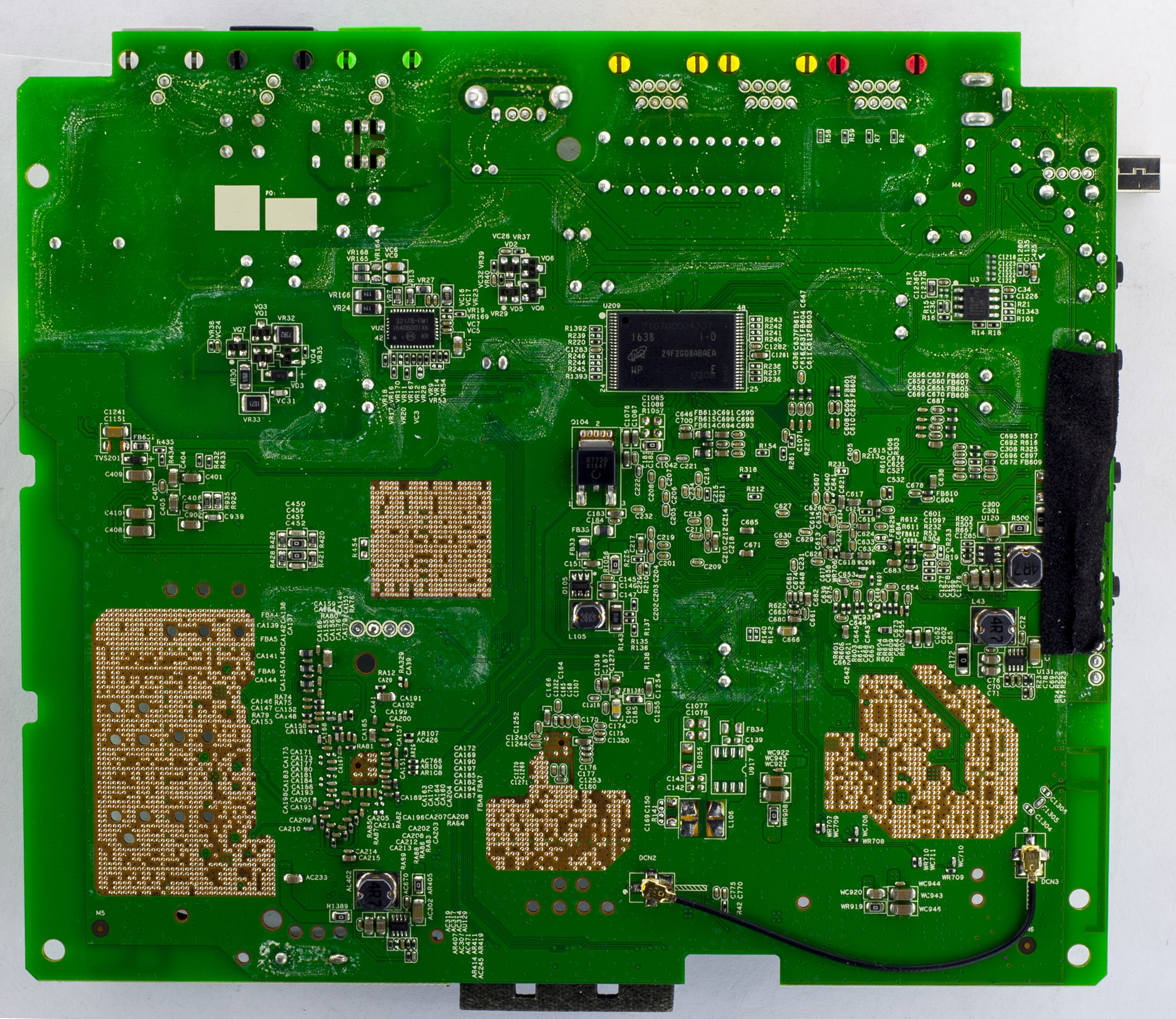
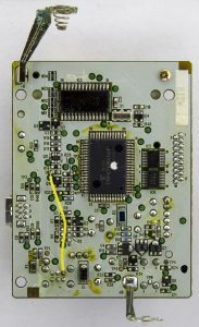
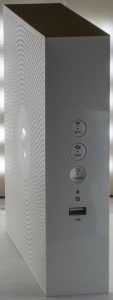
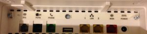
Today we’ll be taking a look at the Telstra F@st 5355 Wifi Router which supports ADSL2+/VDSL2+ on the DSL port, Gigabit WAN port, PSTN and Phone port, 2x 100Mbit LAN ports, 2x USB 2.0 ports, 802.11ac/802.11n Wifi and DECT.

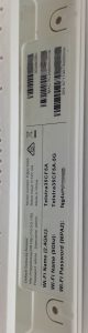
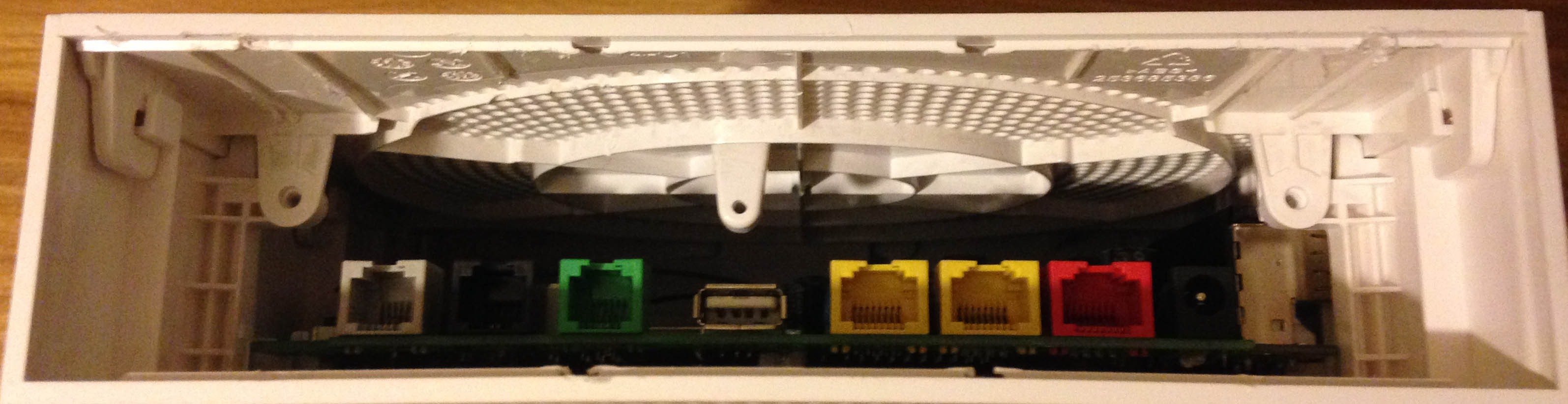
I was trying to look for some screws but couldn’t find any at first until I eventually found there were 3 under the label.
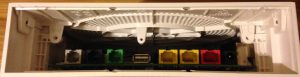
The shell comes out and then you can slide the top off the case.
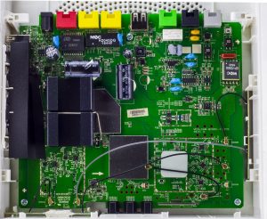
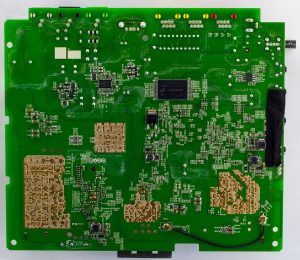
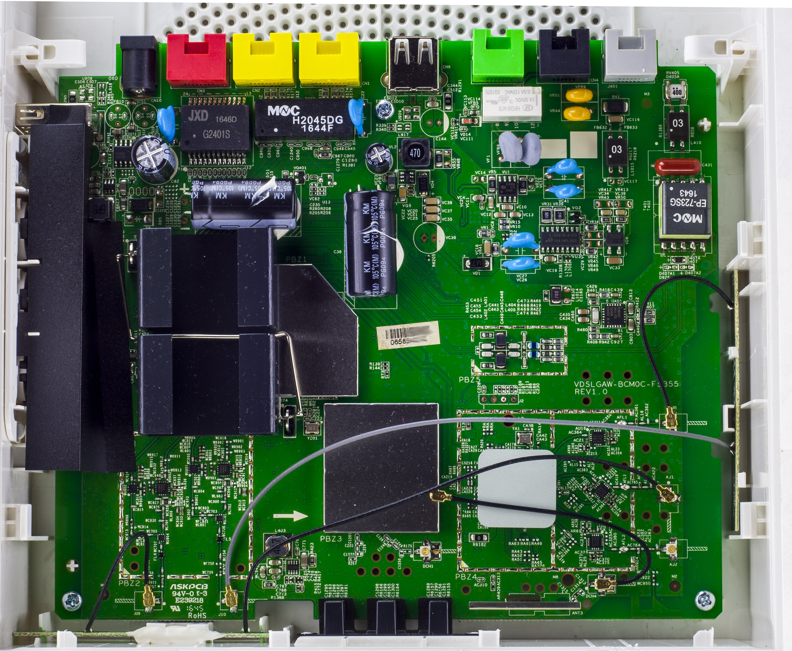
There’s a lot going on, we have a interesting large looking heatsink with a smaller ceramic one, a couple of RF cans, lots of antennas, two large 3300uF capacitors glued down and even more interesting, the back of the board with the exposed pads with it’s via’s looks pretty neat. PCB date code is 45th week of 2016.
(more…)
Read Full Post »
Posted in Teardowns on Jun 24th, 2018
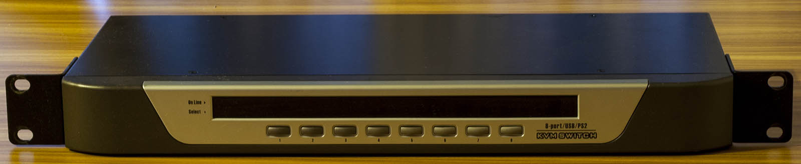
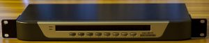
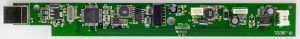
Today we’ll be taking a look at a Generic 8 Port USB/PS2 KVM Switch which has 8 ports which you can switch to with 2x USB/PS2 inputs and a monitor output. There are no markings on the vendor on the outside of the box.
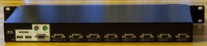
After a few screws we’re in.
(Picture might look a little distorted due to Pano stitching)
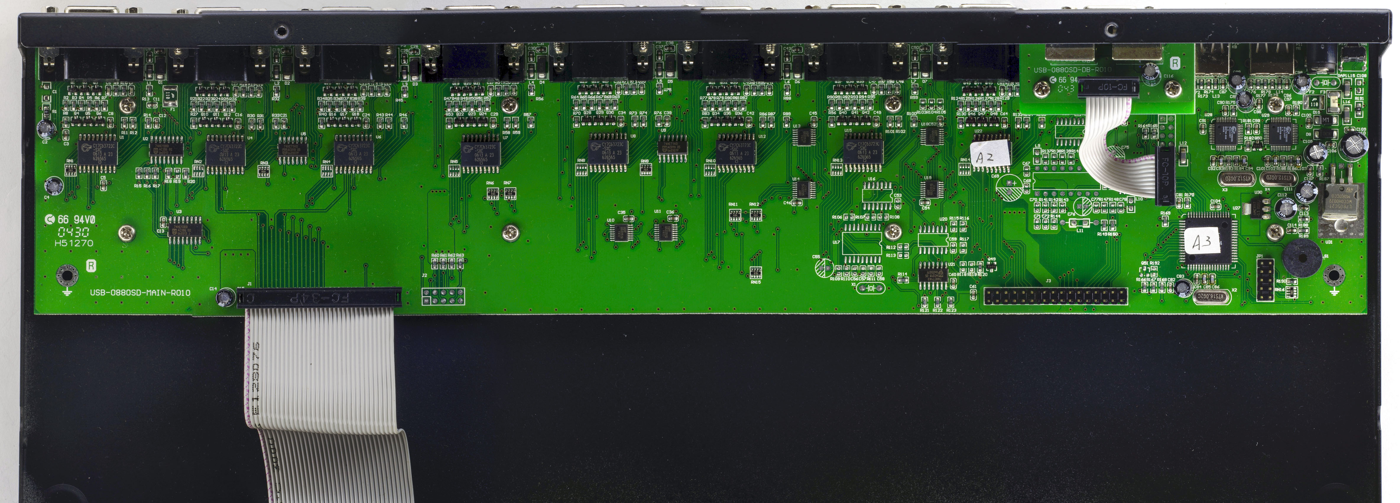
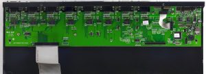
Once inside, we can see the PCB doesn’t use up all of the space available. They are using one chip 8 times (as you might expect), have a little bit of logic (2x 74HC13 and 2x 74HC14), there’s a main chip and a chip for each USB port. There is a 6x 2 pin header for the main chip, the front panel buttons/LEDs connects via a 34 pin connector and there is another 34 pin connector spare with some unpopulated components nearby, wonder what other functionality they could have added. PCB date is 30th week, 2004.
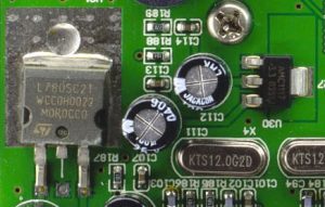
The input voltage to the KVM is 9V so we have an ST L7805 bringing it down to 5V with a decent pad for heat dissipation plus an AMS1117 LDO.
(more…)
Read Full Post »
Posted in Teardowns on May 8th, 2018
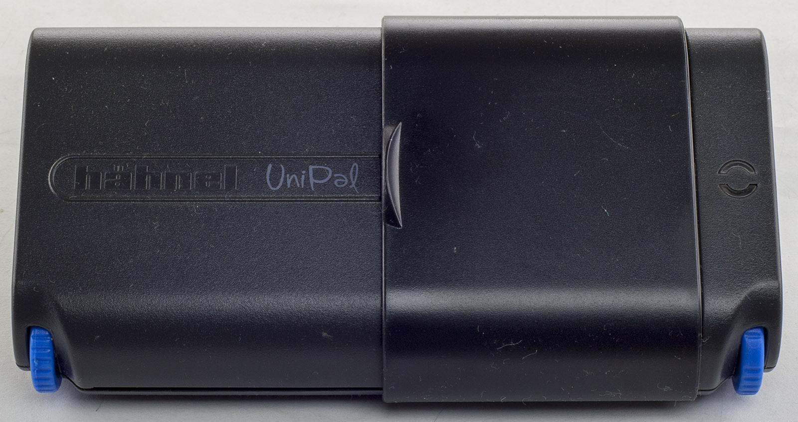
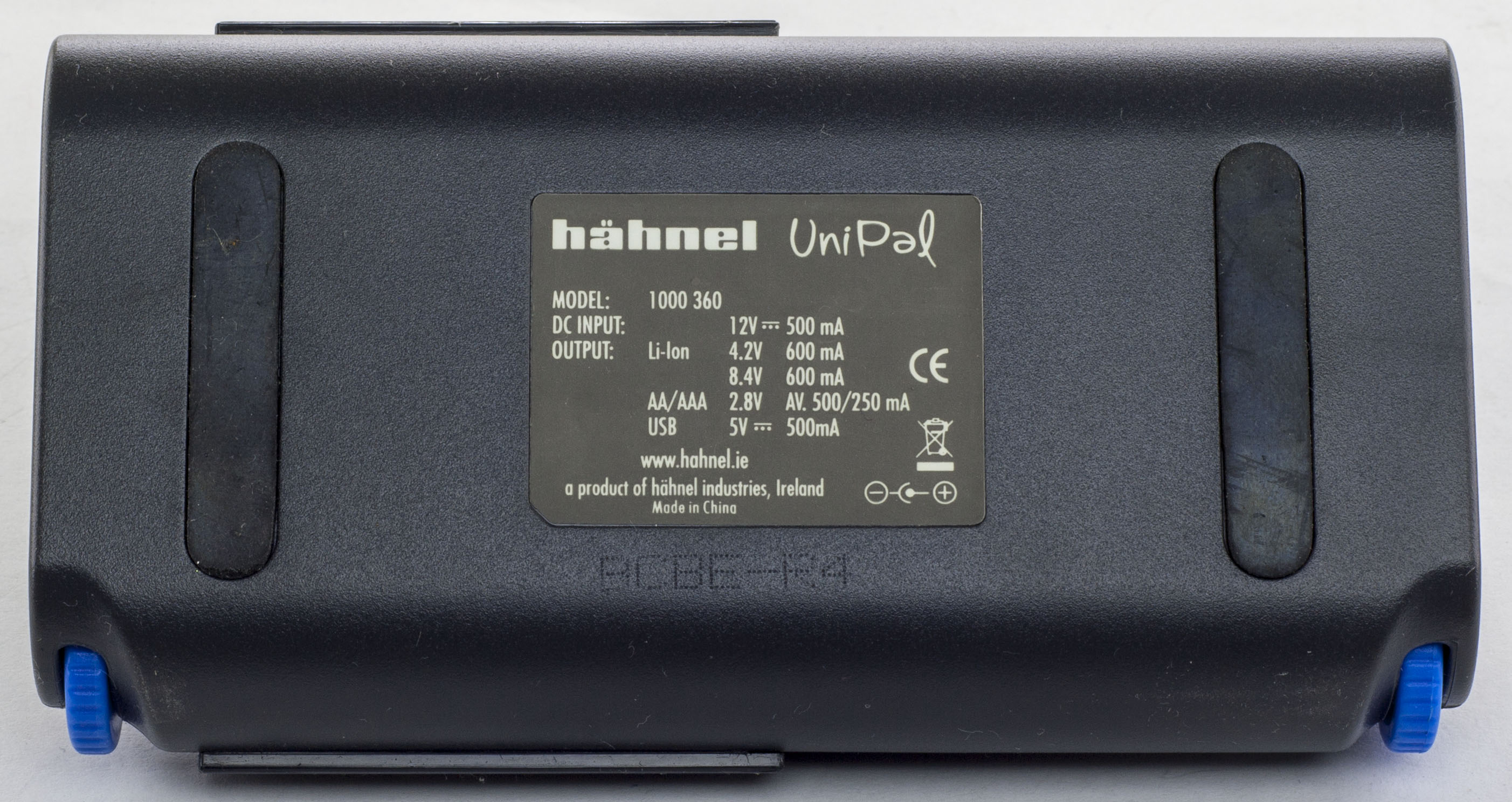
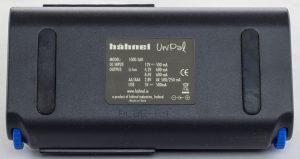
Just a quick one today, we’ll be taking a look at Hahnel UniPal Universal Battery Charger which can charge AA/AAA/Li-Ion and also outputs 5V for USB. This charge allows the user to change the Li-Ion battery contacts via the blue gears.
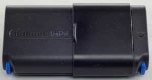
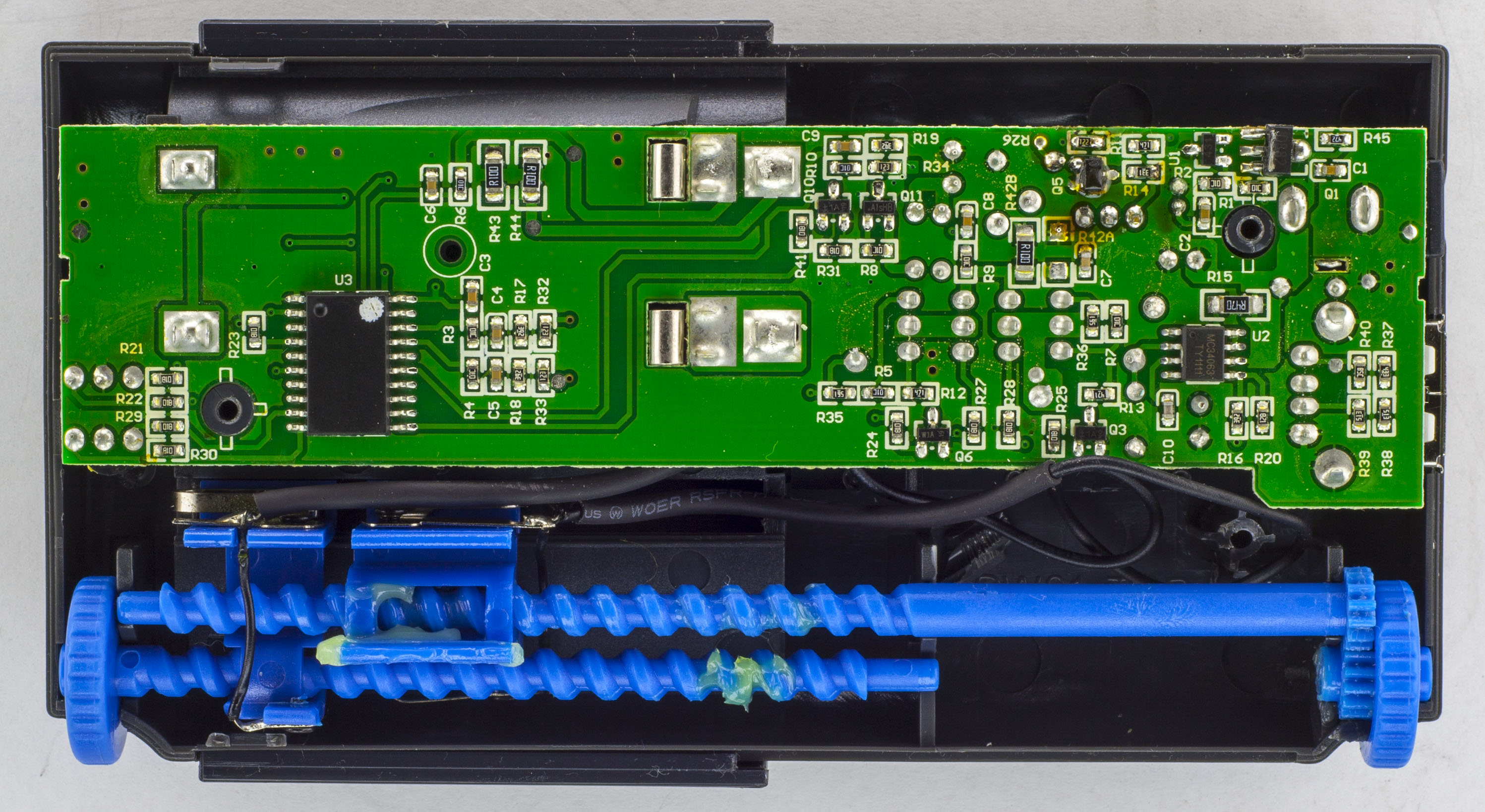
3 screws later and we’re in.
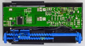

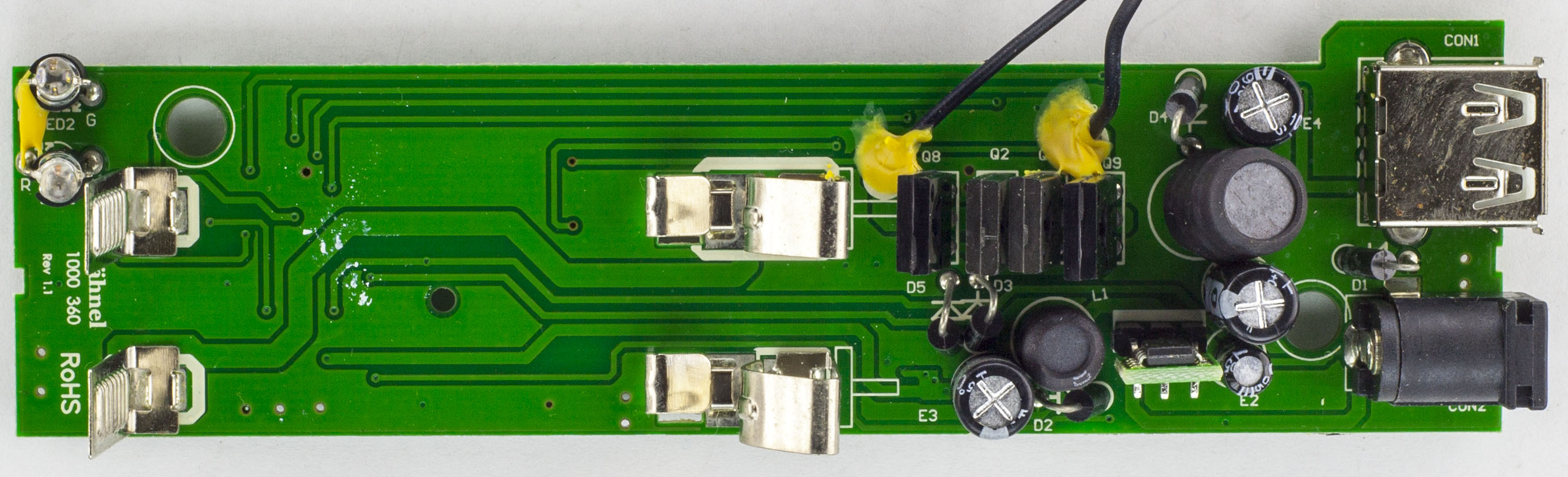
There isn’t too much going on, just a single chip solution and there are no marking on it. You can see how the blue gears and the wires going to the contacts have been heat-shrinked to protect them a bit more.
(more…)
Read Full Post »
Posted in Teardowns on Apr 10th, 2018
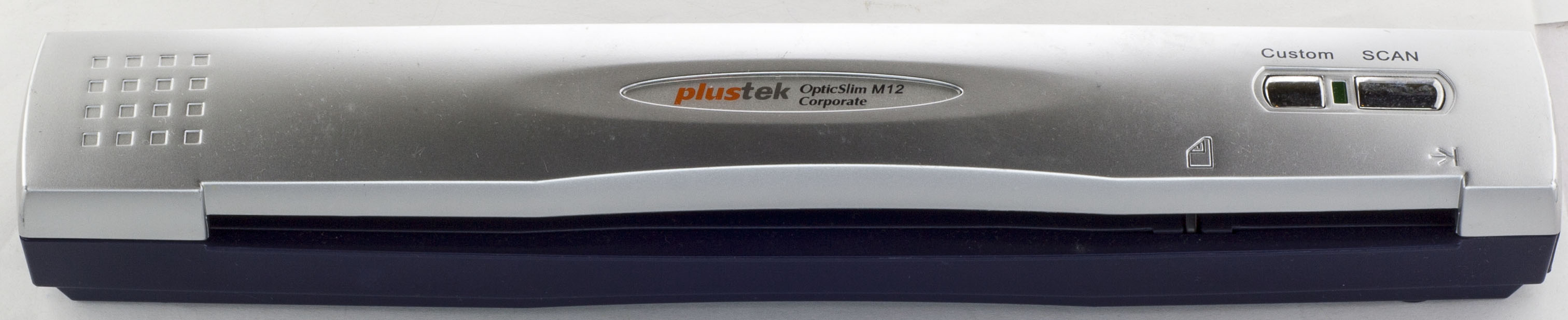
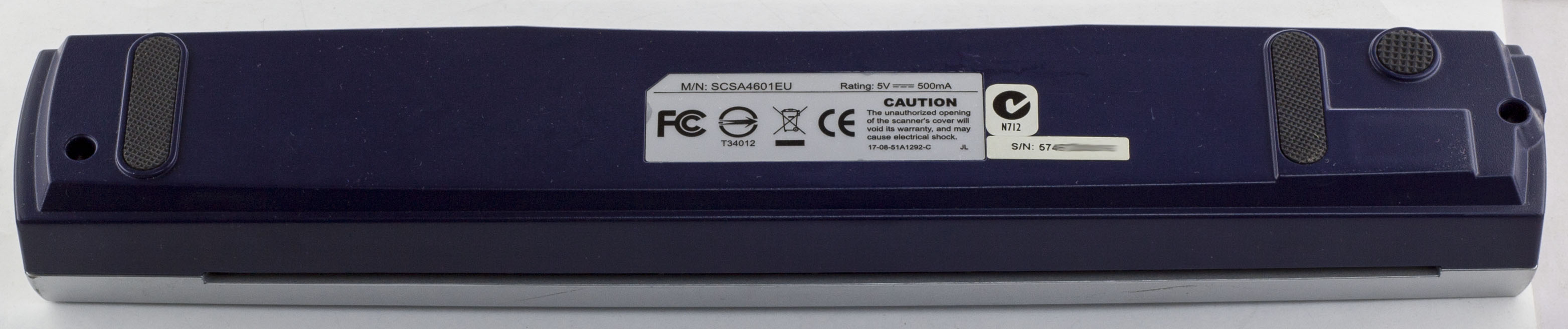
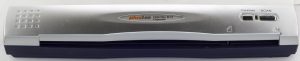
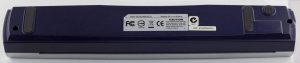
Today we’ll be taking a look at Plustek OpticSlim M12 Corporate USB Scanner which is a single sheet scanner, powered by USB.
2 screws later and we’re in.
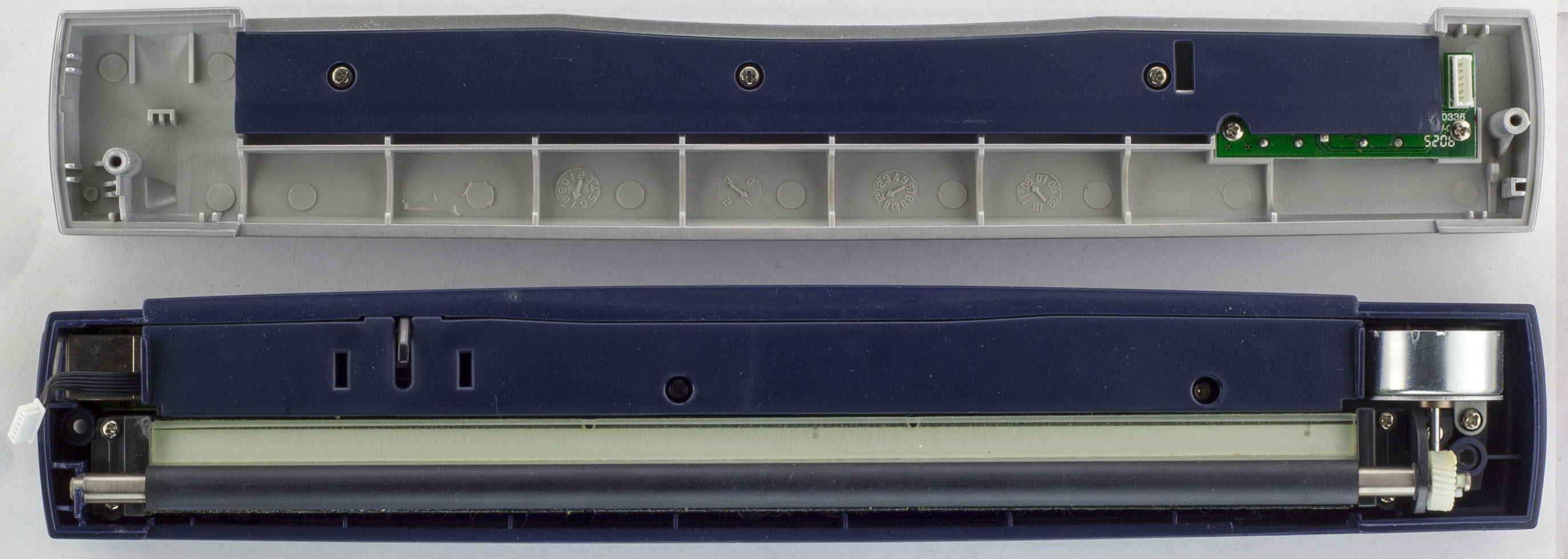
The shell comes apart, we have the small buttons PCB on the top and the scanner and motor on the bottom. A few more screws later and we’ve got to the main PCB.
We have a relatively long PCB that has single chip solution with a motor driver. The scanning element was connected with a flat flex cable. PCB date code is 1st week of 2007 but it’s strange that they have another date code of 2002 on the board, maybe this PCB was part of an older product.
(more…)
Read Full Post »
Posted in Teardowns on Mar 26th, 2018
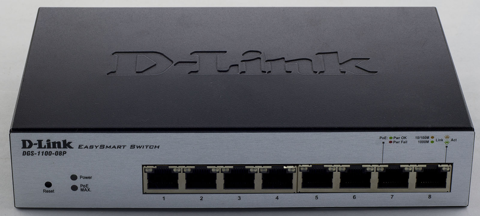
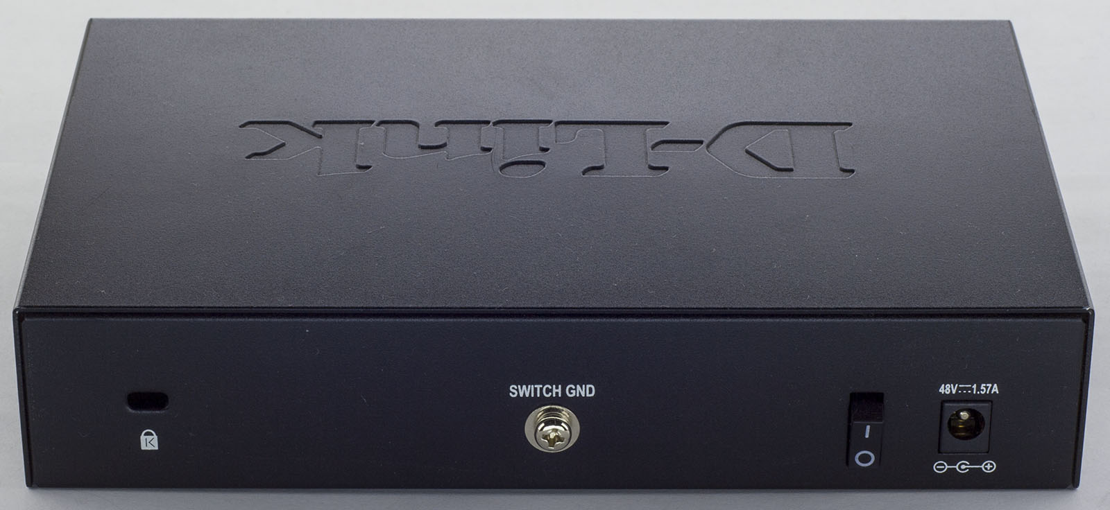
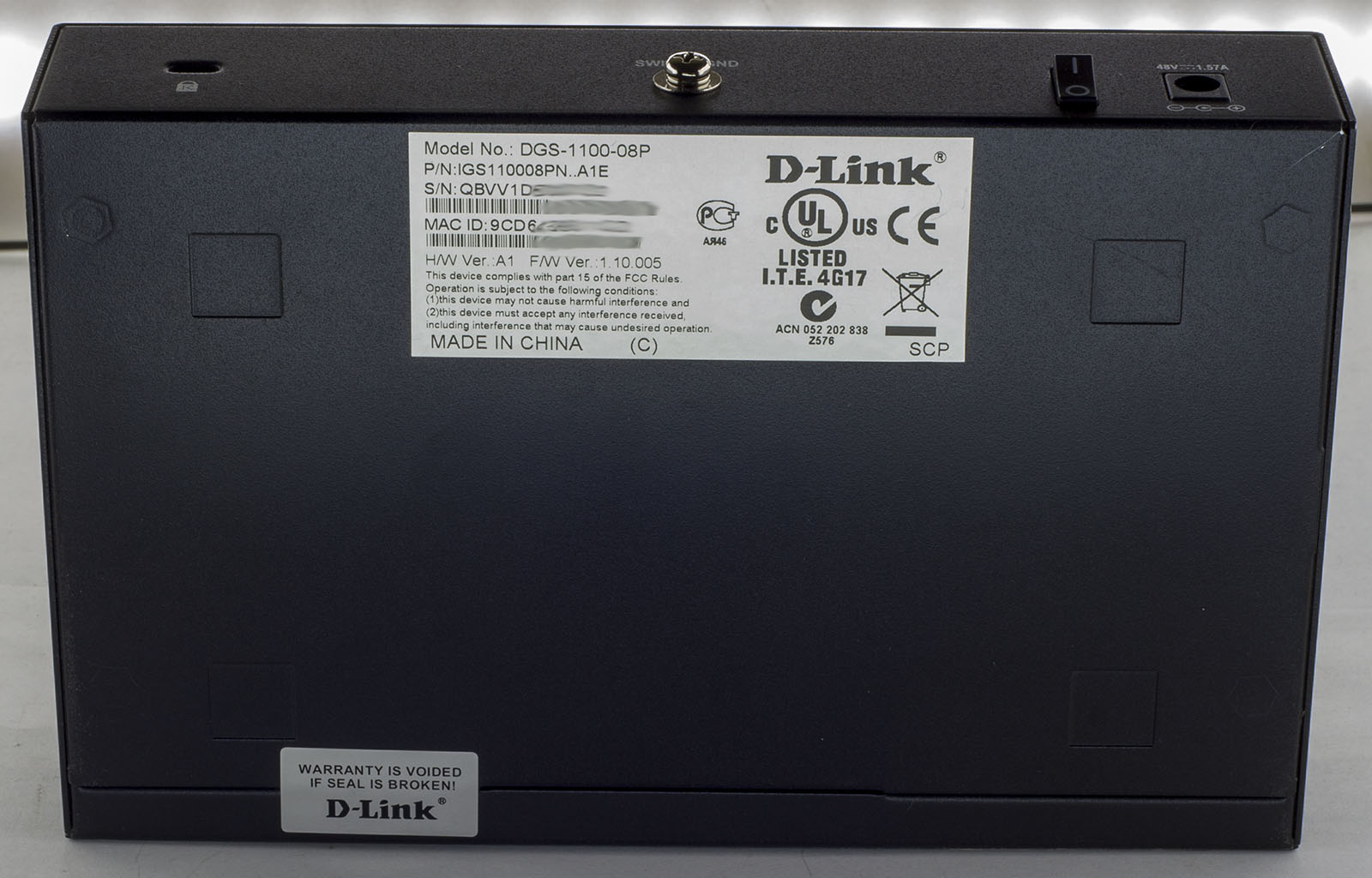
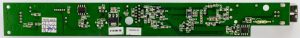
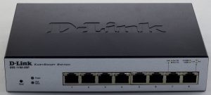
Today we’ll be taking a look at D-Link 8 Port Gigabit EasySmart PoE Switch (DGS-1100-08P) which is an 8 port switch with 8x 10/100/1000 ports with POE rated for up to 64 watts.
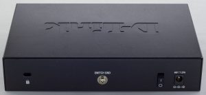
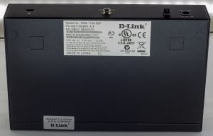
2 screws later and we’re in.
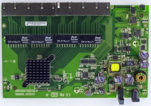
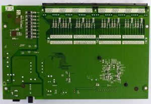
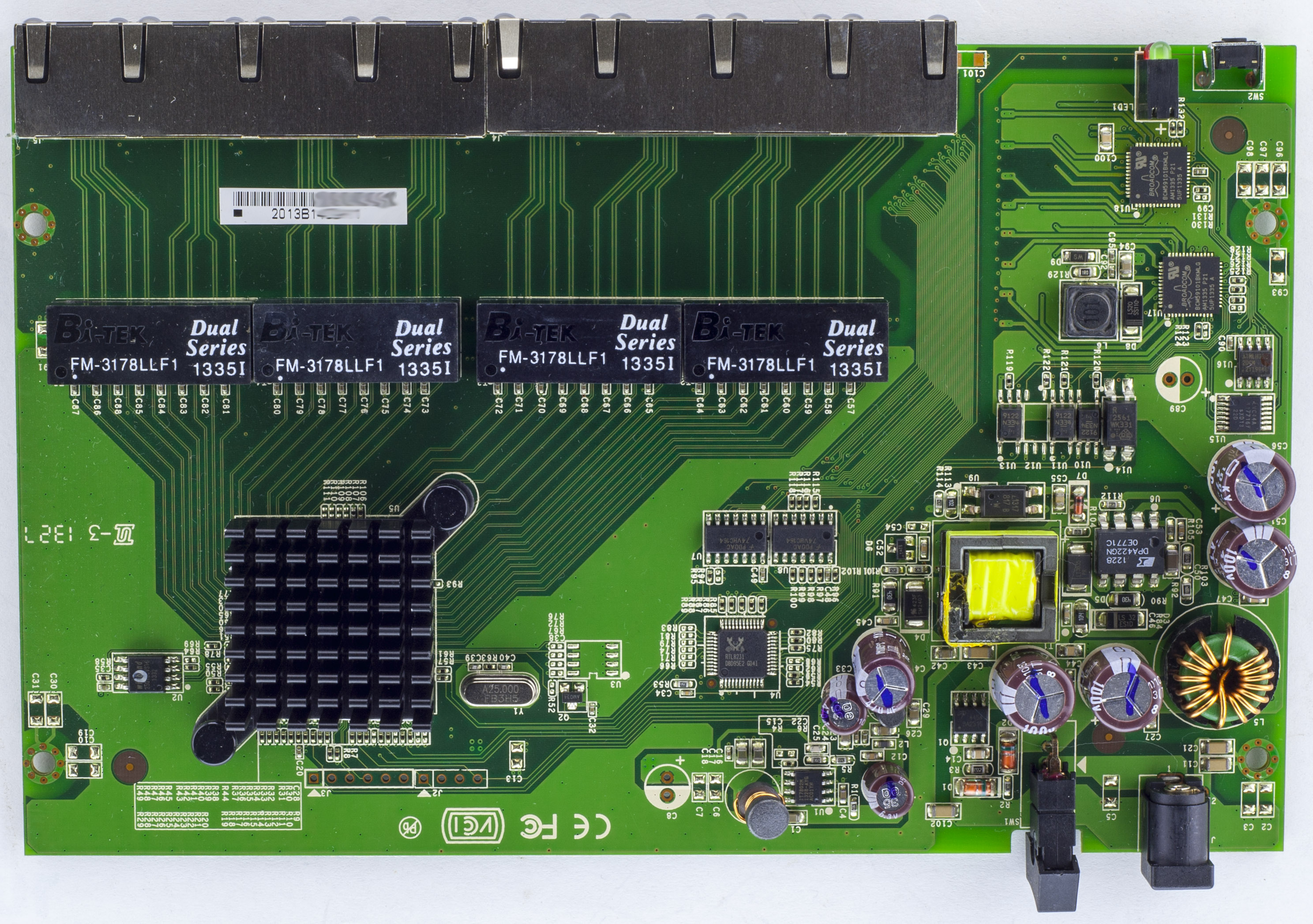
We’ve got our main chip with a decent heatsink plus 3 other chips. The PCB looks to have some isolation with transformers, optoisolaters between the 48V input / PoE side to everything else. We have a few logic chips – LVC14A Inverter and 2x 74VHC164 Shift registers. There are 2 headers, one 4-pin one 6-pin near the main chip. On the bottom of the board, we can see they left off the solder mask for slightly better power dissipation on the PoE chips. PCB date code is 27th week of 2013.
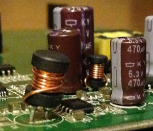
All the electrolytic caps seem to be branded KY. No SMD inductors were used which makes the smaller through hole inductors look a bit strange in how they were placed.
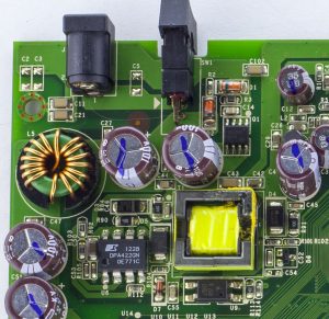
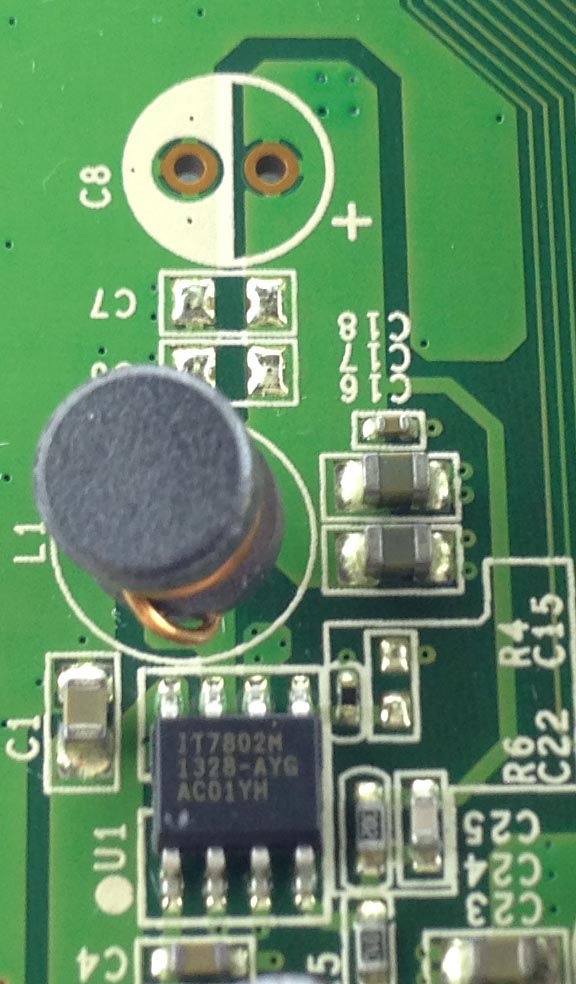
We have the 48V coming in, pass a switch rated for 3A then to the DPA422 DC-DC which provides an output through the transformer to lower the voltage for the M3Tek IT7802 DC-DC which outputs 5V. The 48V input also feeds directly through an choke to the PoE chips.
(more…)
Read Full Post »
Posted in Teardowns on Mar 4th, 2018
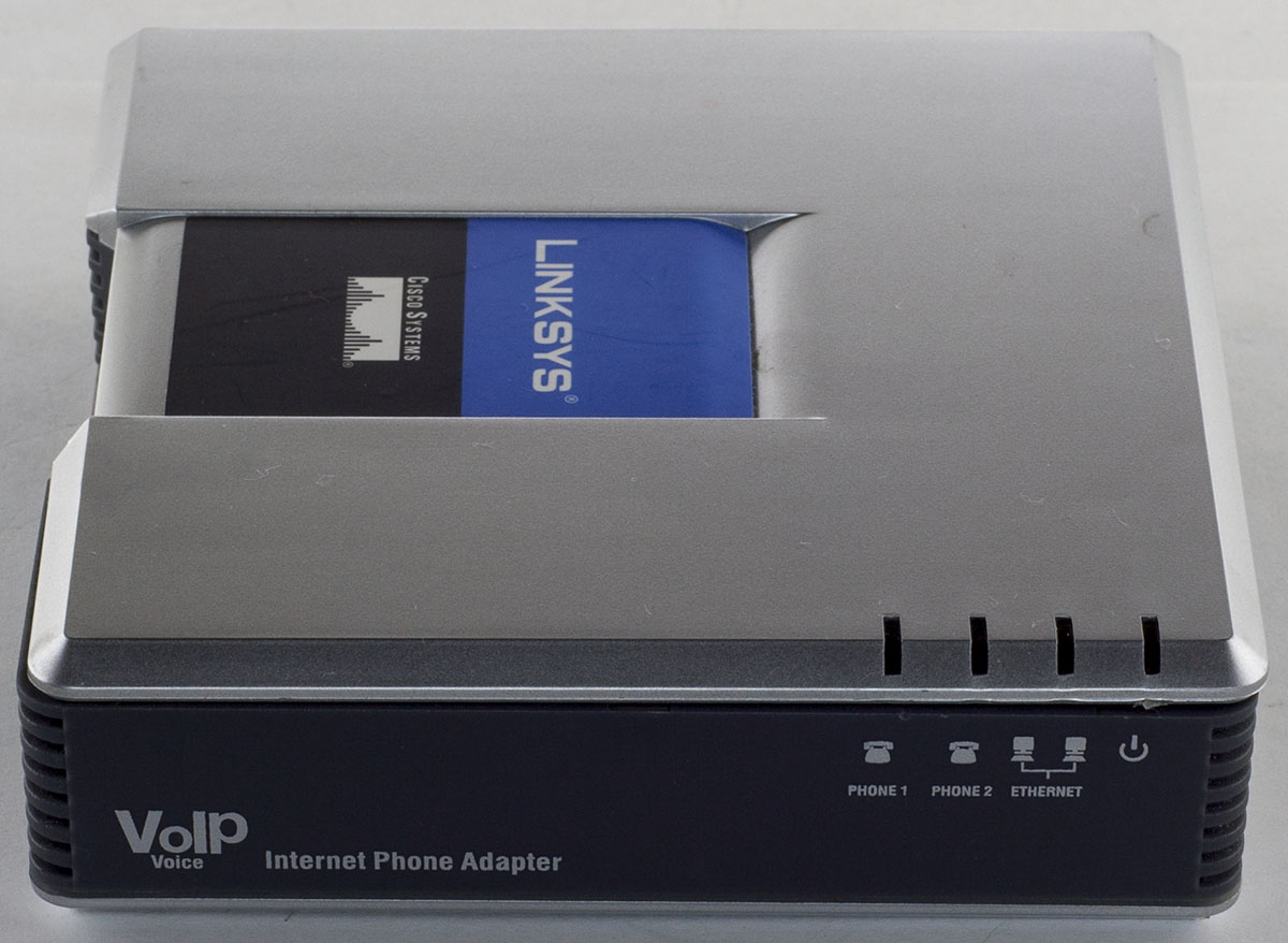
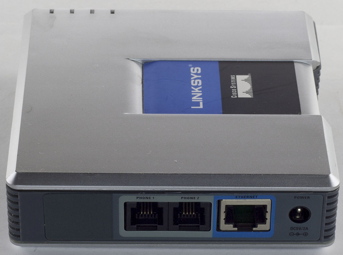
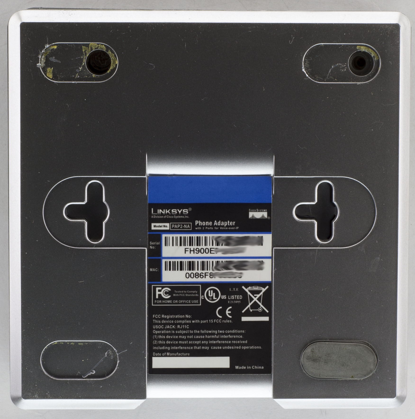
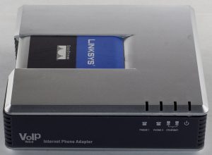
Today we’ll be taking a look at the Linksys PAP2 VoIP Phone Adapter which has an Ethernet port and 2 phone ports for analog phones, powered using a 5V adapter.

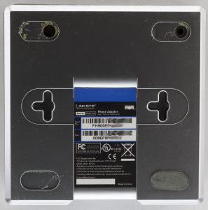
2 screw at the back, 1 screw on the side and we’re in.
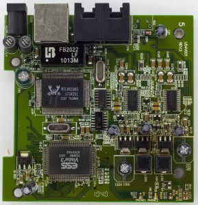
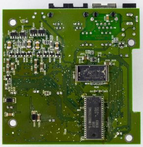
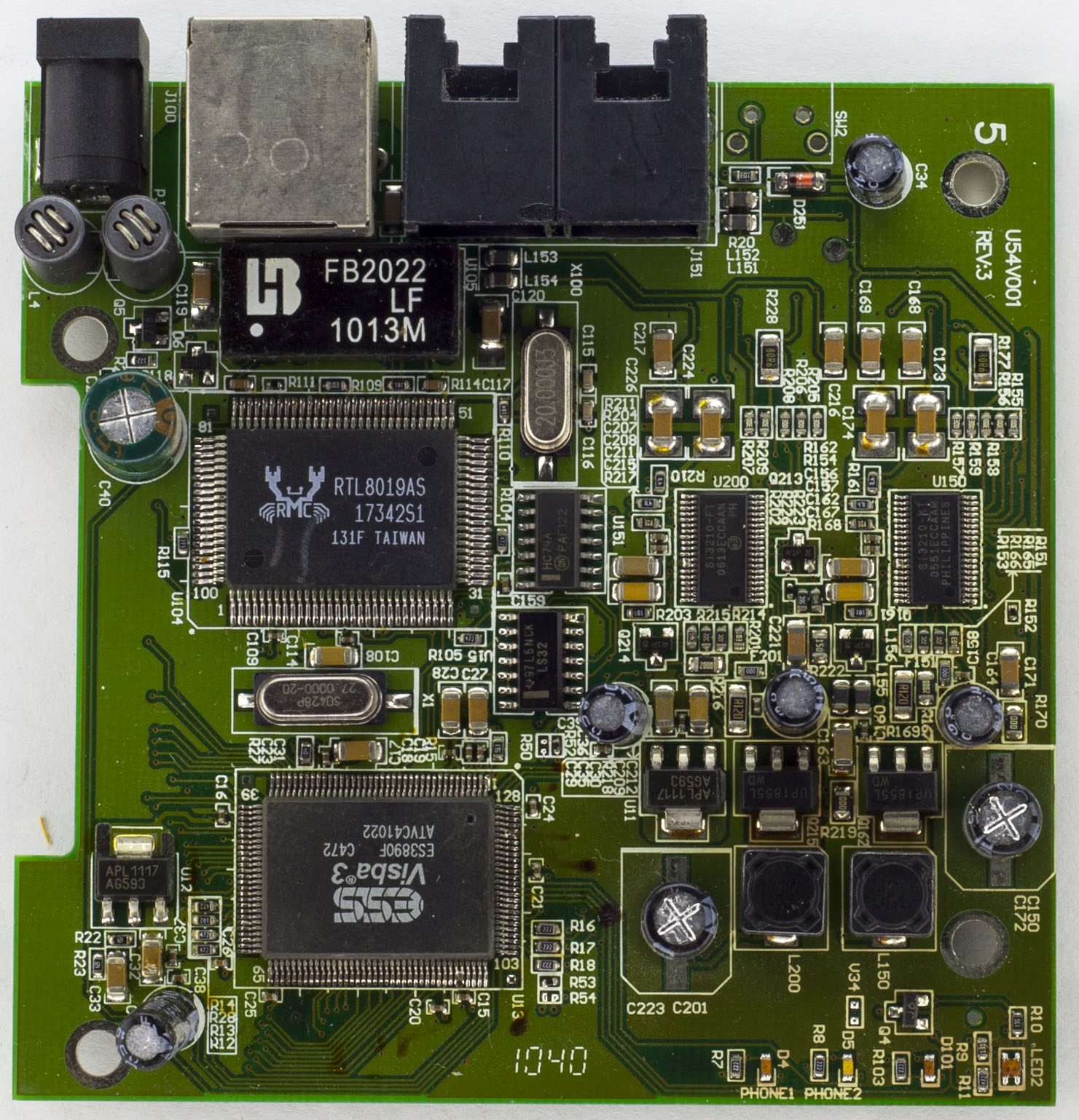
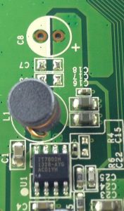
We have a 2 chip solution – the main chip and LAN controller. The bottom of the board looks like it’s seen better days and there are some spots around the board that looks like burn marks, not sure if someone else has opened this up before. For the power side, there are 2 chokes before going through a PNP transitor to a 470uF capacitor and we have 2 AP1117 LDOs giving out 2.5V and 3.3V. There are 2 logic chips around as well, an LS32 a quad OR gate and a HC74 Dual D Flip-Flop with S/R. PCB date code is 40th week of 2010.
(more…)
Read Full Post »
Posted in Teardowns on Feb 15th, 2018
My small bench is located in one corner of the living room next to a sliding door so soldering fumes didn’t appear to be much of an issue when I had a fan blowing the solder away from me.
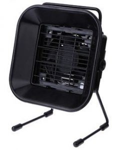
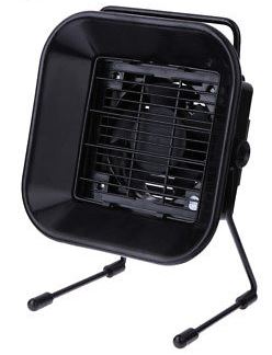
I thought it was probably time for a small upgrade so I bought one of the Solder Fume Extractor’s from Ebay, $24 locally, a bit pricey for what is it. Once I received it, it seemed to work fairly well, the distance you could be away from it and it still suck the fumes was around 15 to 20cm. If you didn’t want it that close, you could always use another fan to gently blow towards the fume extractor or use some materials to focus the suction of air.
After using it for 10 minutes, the fan started to smell and was getting a bit hot too. I left it running for an hour but still had the same issues, ugh, so it was time to take it apart and see what I can swap out.
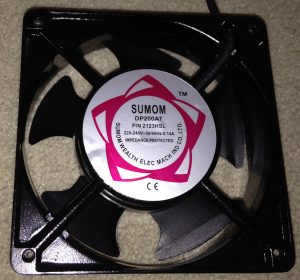
The device has the AC power cord going directly into it, so I thought they might have a AC to DC converter with a DC fan. That wasn’t the case, upon unscrewing the 4 screws at the front, it’s an AC fan. Power is just running though the switch to the fan.
(more…)
Read Full Post »
Posted in Teardowns on Feb 5th, 2018
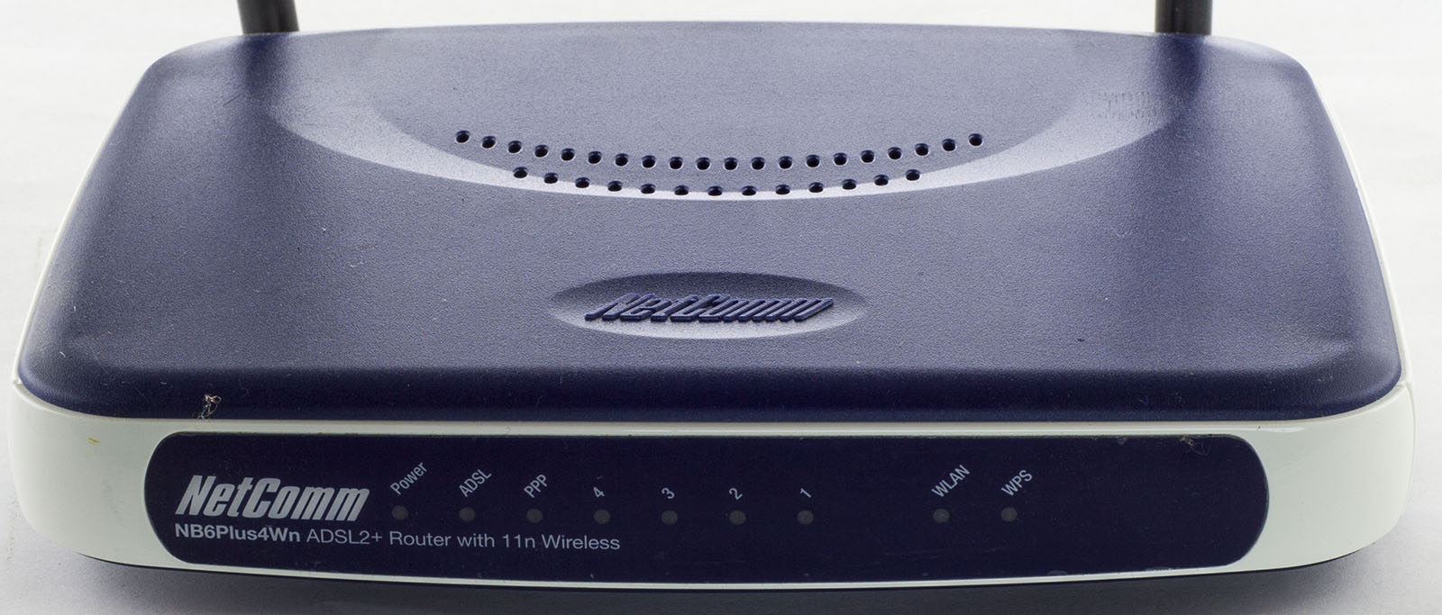
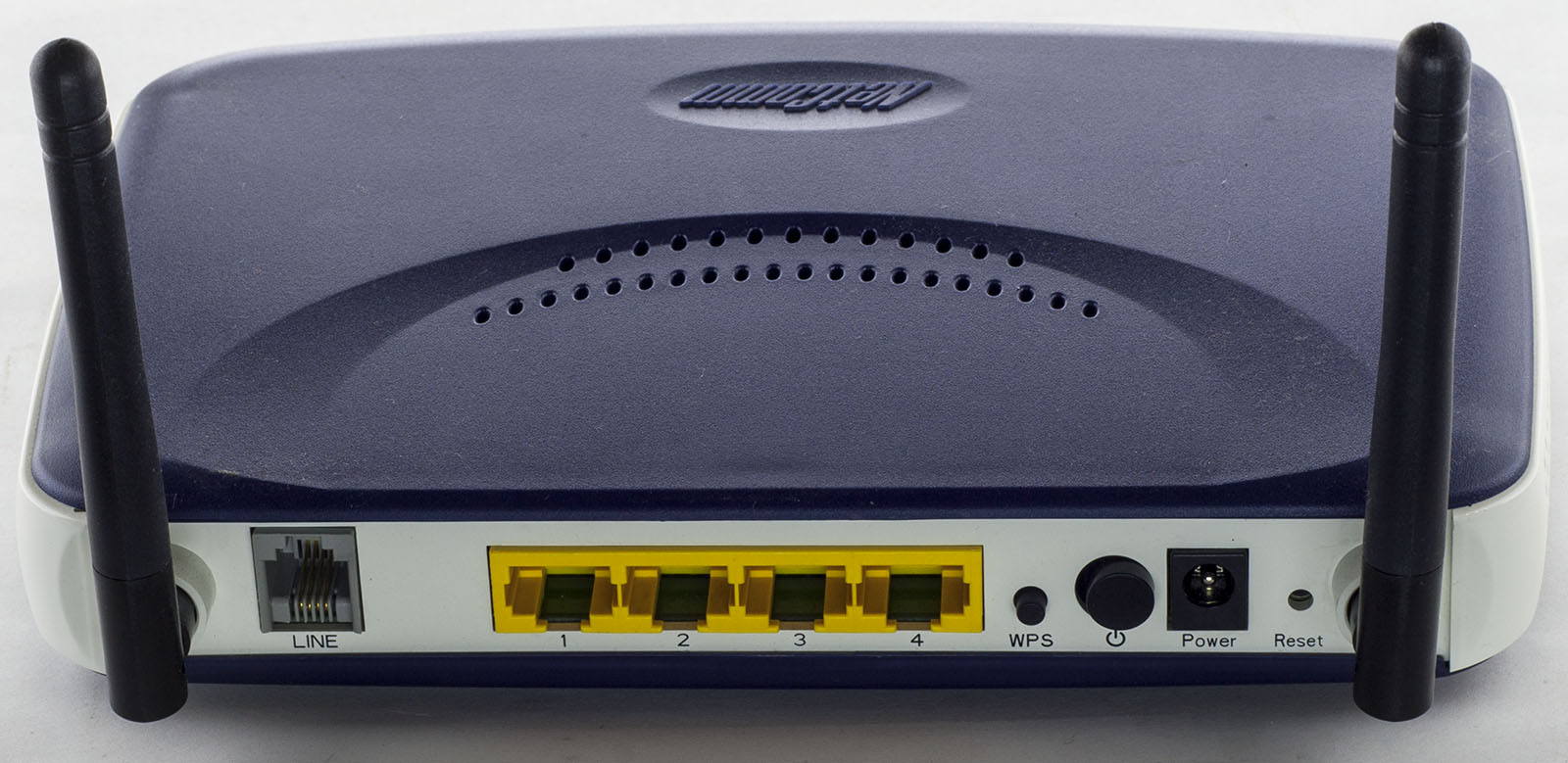
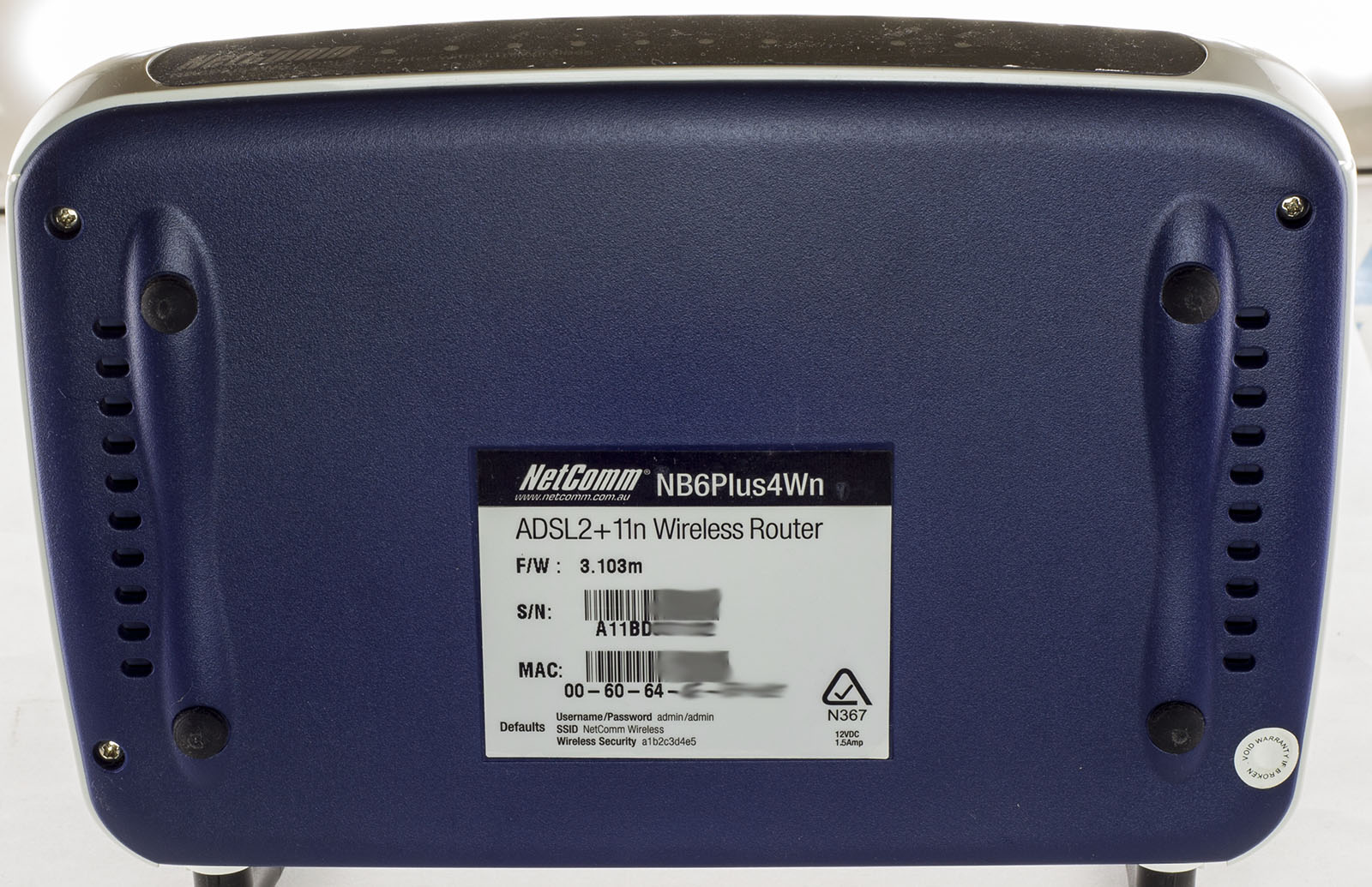
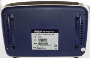
Today we’ll be taking a look at the Netcomm NB6Plus4Wn ADSL2+ Wifi Router which is similar to the Netcomm NB6 Rev2 ADSL2+ we looked at previously except that this one has 802.11n Wifi and 4 LAN ports.
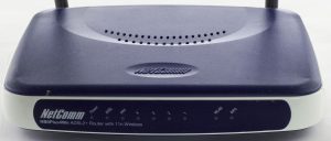
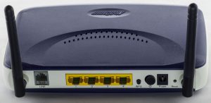
4 screw later and we’re in.

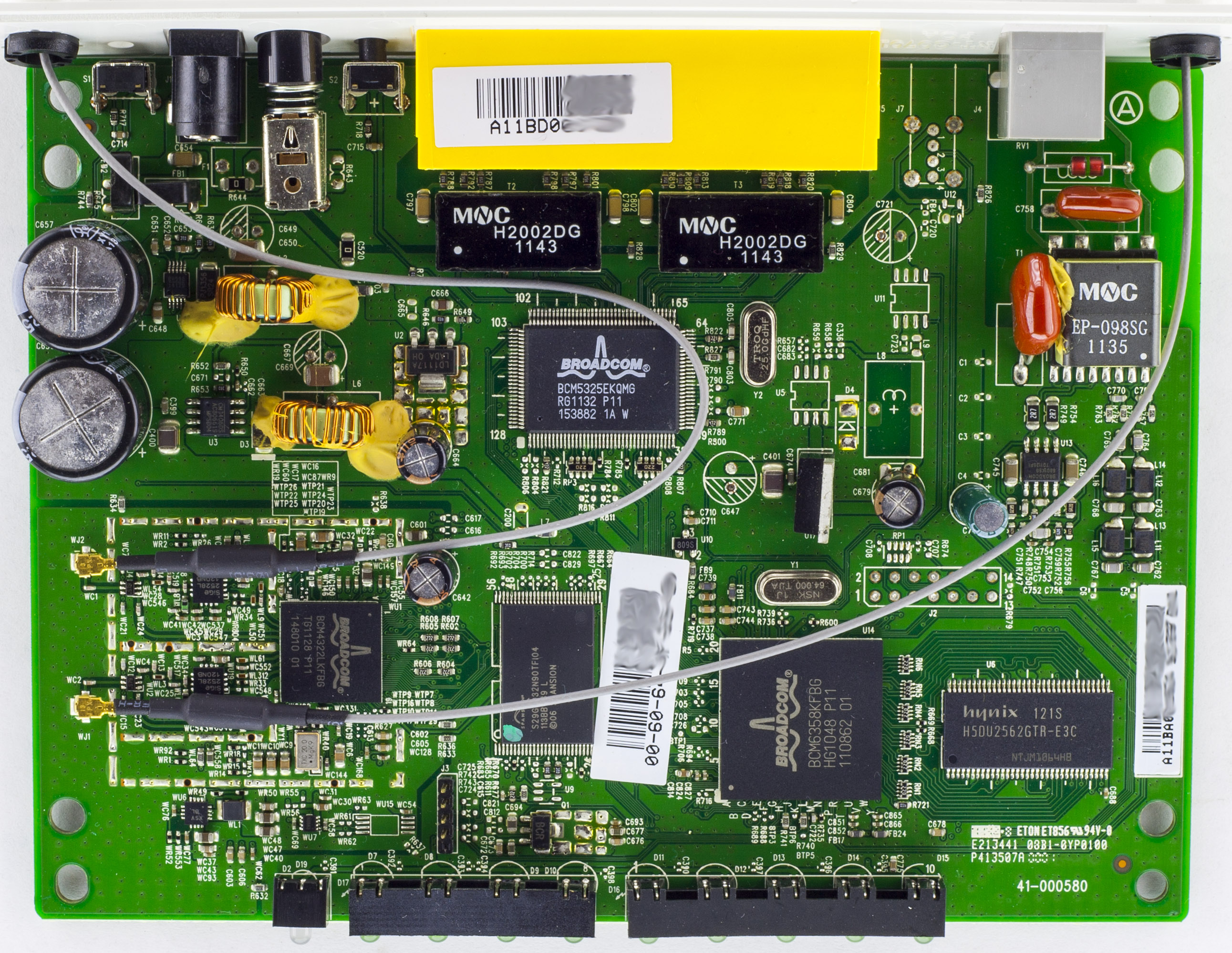
We’ve got a 3 chip solution, the main chip, LAN controller and Wifi controller which is using a discrete front ends for both antennas that look to have a balun in them. There’s a 5 pin header with only 4 pins soldered going to the main chip. Looks like there is also possibility for populating a USB header near the phone line port. PCB date code is 42nd week of 2011.
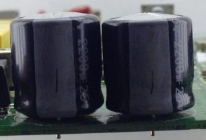
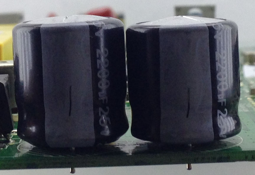
Something that stands out is the 2x Lelon 25V 2200uF caps which are swelling. We have a little bit of glue being used on the 2 inductors for the DC-DC’s as well as the one of the red caps to the line transformer.
(more…)
Read Full Post »
Posted in Teardowns on Jan 2nd, 2018
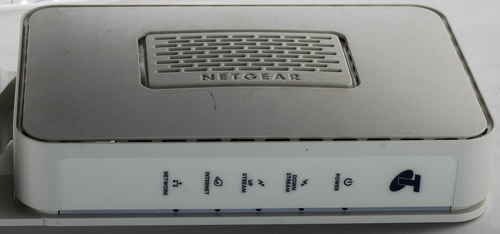
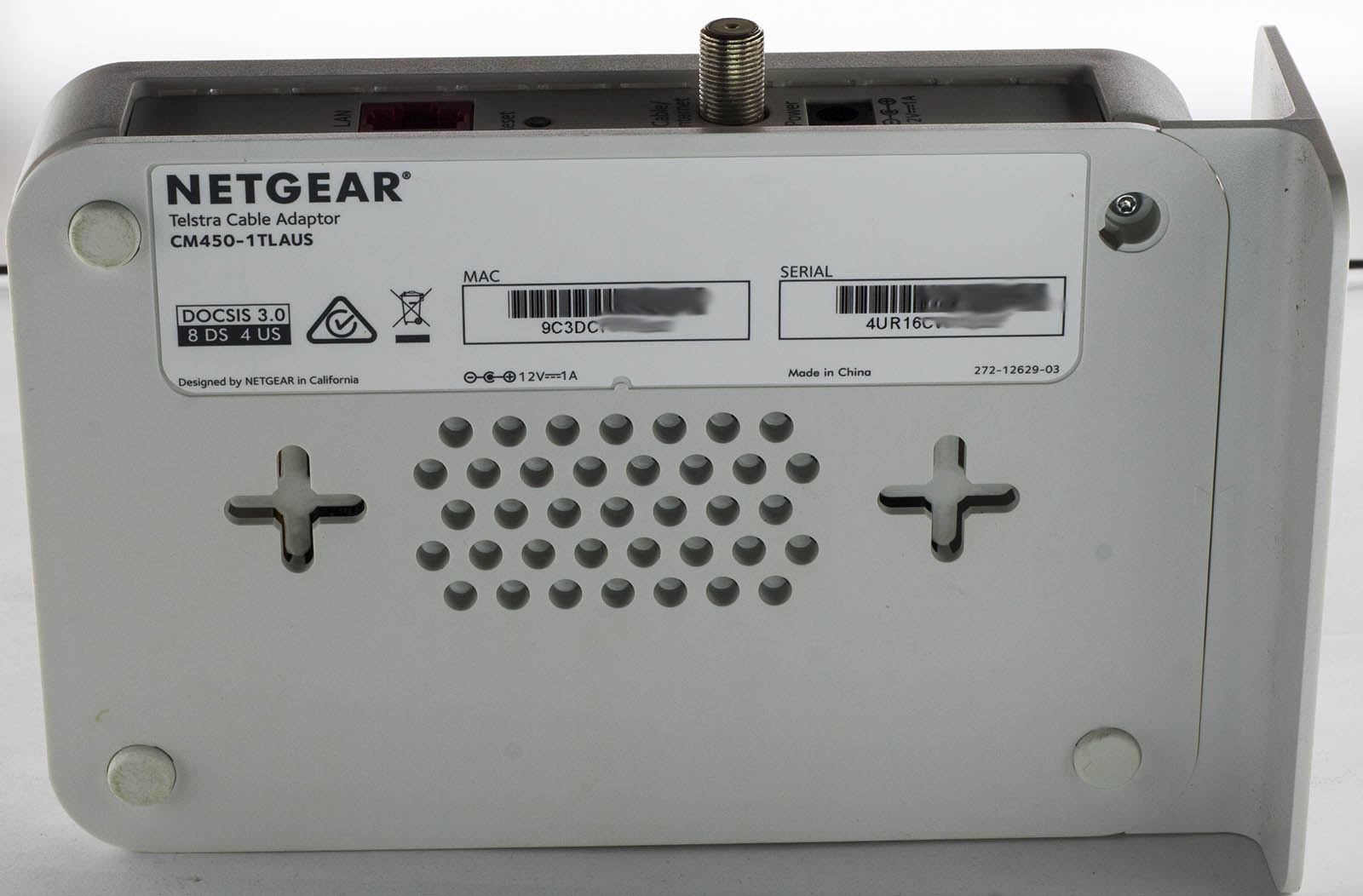
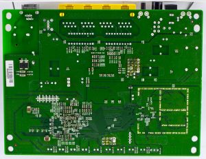
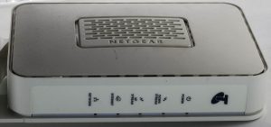
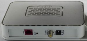
Today we’ll be taking a look at something a little bit modern, the Netgear Telstra Cable Adapter (CM450-1TLAUS) which is a cable modem with just the one Gigabit Ethernet port and RF connector.
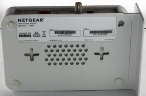
4 screws later and we’re in.
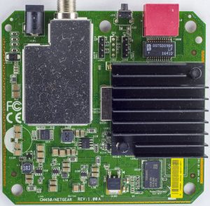
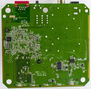
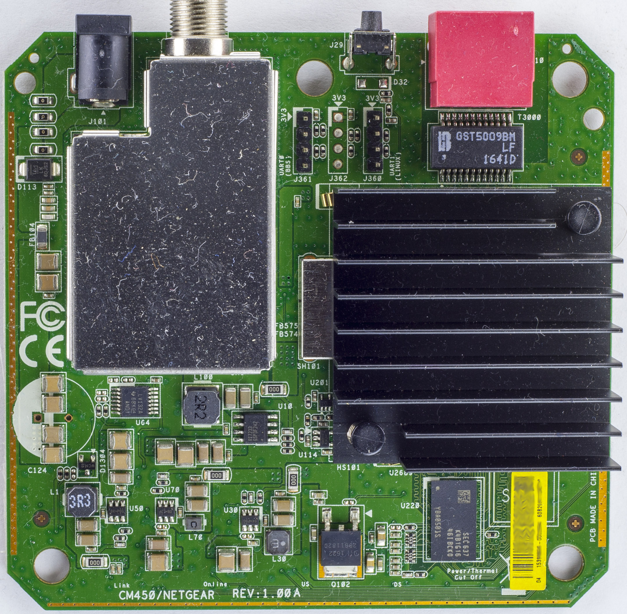
We have a single chip solution with a large heatsink and the RF side has the usual RF shield. They have exposed ground strips on 3 out of the 4 sides of the board and there are no electrolytic caps to be found, they even had a footprint for one to the left but had the option of SMD caps too. Interestingly there are 2x 4 pin headers, labelly nicely, one reads UART0 (BBS) and the other UART1 (LINUX).
We have some logic chips around, an LV132 Quad NAND gate and on the bottom an 74HC74D Dual D-Type Flip-Flop and an LM358 too. PCB Datecode is 45th week of 2016.
For the power side, we have 4x DC-DC converters with inductors ranging from small to large, the largest one is the Richtek RT7233 18V 4A while the others are 6 pin chips (2x 04-P0G, 1x C8-L2P) which I can only assume might also be Richtek chips as the DC-DC’s don’t use an external diode.
(more…)
Read Full Post »