Feed on
Posts
Comments

Category Archive for 'Tinkering'

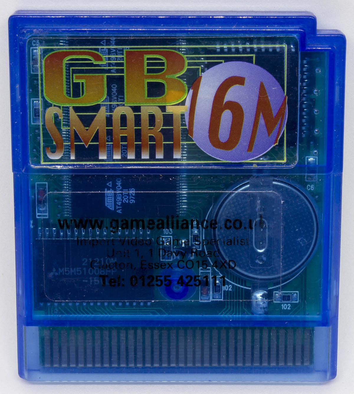
Every now and then I receive an email about adding support for older flash carts but they are usually are hard to find or there isn’t too much information out about them which makes it difficult to add support. I had one user contact me about adding support for the GB Smart 16M flash cart and they were happy to do a swap of my flash cart for theirs. They mentioned it had 4x flash chips which was interesting and were also able to provide me with an empty menu file named GB16M.gb.

A few weeks later it turned up.

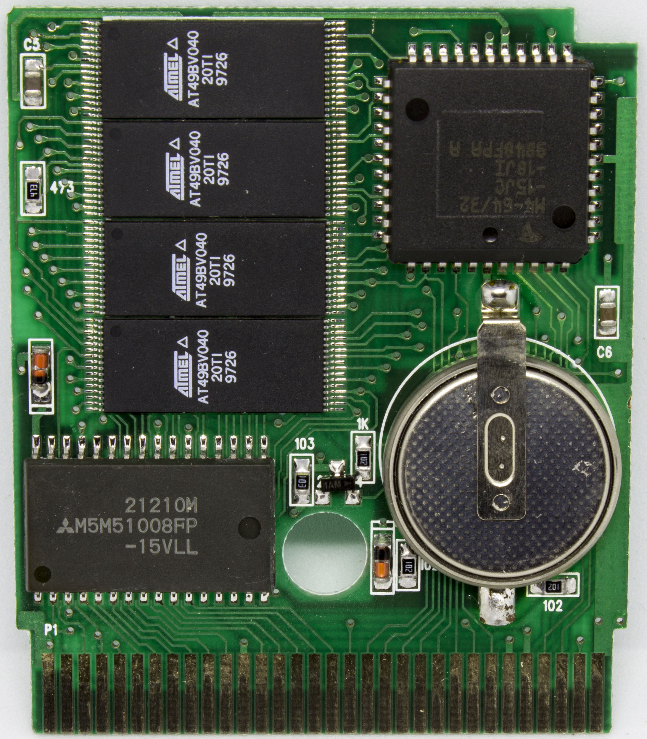
Before receiving it, I was thinking how could they fit 4x flash chips on the cart and then I saw they used the low pin count versions, ah makes sense. Perhaps they choose those because they were cheaper than going with a 2MB flash chip. I plugged the cart into my GBA and it loaded up Super Mario Land straight away so it seems to be working. One thing to be careful of is the battery, it is loosely installed and it sort of slid out when I opened the cart. You wouldn’t want to open it up only to lose your saves!

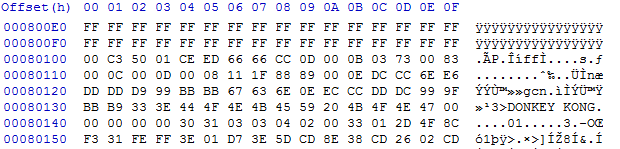
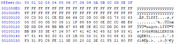
After dumping the cart contents and selecting 2MB as the ROM size, I could see that DK and GB Gallery were also on the cartridge, I’m guessing once we pass the 512KB mark, it switches to the next chip so that means DK started on the 2nd flash chip and GB Gallery started on the 3rd flash chip.

(more…)

Read Full Post »

I’ve playing around with DC-DC step down converters but haven’t really had a need for step-up converters until recently. I have a portable device which requires ~12V 100mA so I’ve been powering it with 4x 3.3V LiFePO4 14500 batteries so it would be nice to reduce the weight a little bit by using a step-up converter knowing that the run-time will decrease.

So I went looking around for some chips and found the Micrel MIC2288 for 90c which supports 2.5V to 10V input, up to 34V output and 1A switch current. A quick look at the datasheet and the BOM looks good and the efficiency chart seems to say it can do at least 100mA at 3.2V so it’s looking good.

So I built it all up, used a 15uH inductor instead of the 10uH they showed. On the output I got 11.8V so all seemed well, put a 1.5K resistor (8mA load) which was fine, then I tried 330 ohm (36mA load) and that’s when I saw the voltage drop to 9V or so on the multimeter, strange plus I heard some sounds coming from the circuit. I started bumping up the voltage from 3.3V and once I hit 5.2V the output seemed to go back to 11.8V. I went back the other way, once I hit 2.3V to 2.8V it started working normally again. No components were getting hot.

I swapped the inductor for a 22uH one, same issue. I was about to measure the voltage across the Schottky diode when I touched the first lead to the SW (point where the inductor and Schottky diode meet) and the sound went away and the voltage went back to 11.8V. The current draw at 3.3V input was 150mA and it stayed the same when touching the SW pin. I swapped out the Schottky diode for a larger one but there was no change and touching the SW pin didn’t work this time.

(more…)

Read Full Post »

About a month ago I was working on fixing a bug when writing 1Mbit flash saves back to a GBA cart when I decided to plug in a “24 in 1” Flash cart to see if it had flash memory as the save option (it doesn’t, it has 512Kbit SRAM) but when I saved the SRAM and then re-read the header something strange happened, the game title changed to another game. I tried it a few more times and could replicate it fine, turns out there was another bug, I was switching banks (512K to 1M) even for SRAM carts too. This is just a quick post about my findings.

After some quick investigation of what was happening when switching banks on the Flash cart, I narrowed it down to the 0x2AAA, 0x55 command which could be run by itself to switch the game title. I started testing bits on that address and byte, I found that if you gave it a wrong address or byte, it could potentially lock up and only give you the same game title over and over again or the game title could have a random character or two.

2 = 17, 3 = 24, 4 = 0, Game title: BOF2
2 = 17, 3 = 24, 4 = 1, Game title: BOF2
2 = 17, 3 = 24, 4 = 2, Game title: BOF2
2 = 17, 3 = 24, 4 = 3, Game title: BOF2
2 = 17, 3 = 24, 4 = 4, Game title: BOF2
2 = 17, 3 = 24, 4 = 5, Game title: BOF2
2 = 17, 3 = 24, 4 = 6, Game title: BOF2
2 = 17, 3 = 24, 4 = 7, Game title: BOF2
... 
2 = 17, 3 = 24, 4 = 16, Game title: BOF EUR
2 = 17, 3 = 24, 4 = 17, Game title: BOF EUR
2 = 17, 3 = 24, 4 = 18, Game title: BOF EUR
2 = 17, 3 = 24, 4 = 19, Game title: BOF EUR
2 = 17, 3 = 24, 4 = 20, Game title: BOF EUR
2 = 17, 3 = 24, 4 = 21, Game title: BOF EUR
2 = 17, 3 = 24, 4 = 22, Game title: BOF EUR
2 = 17, 3 = 24, 4 = 23, Game title: BOF EUR

I found that at address 2, you could write the high bits of the byte and it would switch banks, like 0x10, 0x20, but it didn’t change all the time. Later on I played around with writing any number to it and it would change on even numbers. Address 0 and 1 didn’t seem to do anything. See a bigger list here of addresses / game titles here: Address-to-game-titles

(more…)

Read Full Post »

You might already know that it’s possible to backup your Gameboy camera’s memory to a save file and extract the images / convert them to BMP using a program called GBCameraDump. I had a request from a user asking if there was a way to automate this whole process. There are products which I didn’t know about such as the BitBoy which saves the images to SD card without a PC which is very handy if you use the GB camera very frequently as it can only store 30 images.

I took a look into this request as automating it could make it be as simple as plug in GBxCart RW with the GB camera, run a single file and it’ll do the rest. First thing was to take a look at the source of GBCameraDump, the author mentioned that GBCameraPic.cpp was the important file to look at. I was hoping at first that there might be an way to easily convert this GUI program into a command line program so I could call it after dumping the save game.

void __fastcall TGBCameraPic::DrawPic(int Number)
{
    int count=(Number+1)* 0x1000;
    for (int y=0;y<14;y++)
    {
    for (int x=0;x<16;x++)
    {
		for (int row=0;row<8;row++)
		{
 			Byte temp1=SaveRam[count++];
        	Byte temp2=SaveRam[count++];
        	for (int pixel=7;pixel>=0;pixel--)
        	{
                Picture->Canvas->Pixels[(x*8)+pixel][(y*8)+row]=Clr[(Byte)((temp1 & 1)+((temp2 & 1)*2))];
        		temp1>>=1;
            	temp2>>=1;
        	}
    	}
     }
     }
     Canvas->Draw(0,0,Picture);
}

It looks like the images in the save file start at 0x2000 and are in multiples of 0x1000. The source didn’t look too complicated however it appears that they are using the Bitmap library (TBitmap) which seems to be included in the compiler they used Borland Cbuilder5 (found by opening the .obj file).

I was starting to take a look at this all and my options, I started thinking that it’s just a BMP file, surely I could just figure it out without a library right? So I started to play around with the BMP files that GBCameraDump created and the GB camera save files too, changing one bit here, noticing what changed, changing another bit there, etc, here’s my findings – (more…)

Read Full Post »

Lately my blog has been focused on quadcopters / RC cars and here’s another little one, I’ve been wanting to try out Acro mode but would rather not crash a whole lot to test it out. There’s a program called FPV Freerider which lets you simulate the quadcopter on a few different maps. Normally you would use a Flight Simulator Cable however I didn’t want to wait and they were out of stock locally.

fpv_4

I happened to stumble upon Giuseppe’s Urso’s Blog which had some code for this exact purpose but for some reason only my first channel was working with my Turnigy iA6 receiver. The format being sent by 9600 baud serial was the FMS PIC 9600 which involves a special byte mixed in with the number of channels, another byte for buttons and then each channel has it’s own byte ranging from 0 to 255. Now that we have the format, I can write some code.

fpv_3

I found that my iA6 receiver outputs all it’s channels at the same time, i.e all at the same time and not one after another like some other receivers might, it actually makes it easier for us as all we need is an interrupt on any of the pins and then we start counting. Connect RX channel 1 to Arduino pin 2, RX channel 2 to Arduino pin 3 and so on.

#define RX_CHANNELS 4

volatile uint16_t ch1Result = 127;
...

void setup() {
  Serial.begin(9600);
  
  // Set inputs
  for (uint8_t x = 2; x < RX_CHANNELS + 2; x++) {
    pinMode(x,INPUT);
  }
  
  // Attach interrupt to pin 2 as rising
  attachInterrupt(0, time_channels, RISING);

  // Reuse Timer1 to count the microseconds after pin 2, etc go high
  TCCR1A = 0;
  TIMSK1 = 0;
  TIFR1 = 0;
  TCNT1 = 0;
  TCCR1B = (1<<CS10);
}

After playing around with the Arduino micros function, it had glitching every few results so I used the timers directly. We setup the pins as inputs, attach the interrupt INT0 to pin 2 to only trigger when the pin goes high and reset the timer to the default.

(more…)

Read Full Post »

Update 23 May 2017: There is an easier way to get Error rate in Betaflight, update your i6 transmitter with the 10Ch mod and specify Error as a channel , no soldering required – https://github.com/benb0jangles/FlySky-i6-Mod-/issues/17#issuecomment-278679083 (be aware, it will wipe your model memory)

Previously I was able to modify the Turnigy TGY-i6 transmitter to read the signal strength (RSSI) byte and illuminate an LED near the FPV display if the error rate was high so you could easily tell that it’s probably a good idea to turn around. There was a comment from Paul asking if there was a way to read the RSSI from the receiver itself and then pass this onto the flight controller or OSD. (This isn’t really RSSI but just error rate which is a good indicator when you are going to lose signal as you are too far away)

https://www.youtube.com/watch?v=uHnYfxDknrY

This sounded like a good idea so I went ahead and did just that with a spare iA6 receiver (I suspect the iA6B should be the same. Edit – it’s different, see end of post). Firstly lets do a quick teardown of the receiver.

IMG_4224IMG_4221

On the top we’ve got our 2 antennas going to the RF can with a microcontroller (TG84023) which would be converting the incoming data to the 6 channels, an 8MHz crystal/oscillator and on the bottom we have another MCU (no label). The PCB marking reads FS-iA6 (Flysky branded), 20130217 and it’s got 3.3V and 5V which I’ve verified so the little 3 or 6 pin packages would be an LDO for 3.3V and DC-DC boost/buck for the 5V and I think the inductor is under the white potting compound.

ia6-rssi-3 ia6-rssi-4

After a bit of probing around, the MCU on the bottom looked to be producing a clock output of 1MHz and some serial data. One initial problem that I thought might be an issue is with syncing the serial data to the clock pulses as at the start and near the middle there is a 4 clock block but it turns out there is an even number of them so it works out just fine.

(more…)

Read Full Post »

I’ve mentioned before that I’ve been looking into quadcopters and built my ZMR250 quadcopter a few months ago which is working well, a few modifications have been made here and there; and some are still to come.

IMG_1186_1 IMG_1504_1

One problem with the transmitter is that there isn’t a way that I’ve found to make it beep or light up if you exceed a certain communication error rate, the further you go or the more objects in your line of sight, the higher the error rate becomes. You can glance down at the remote and check it there but when you are focused on your FPV monitor you can easily forgot so I would like a better way. There may be a way to do it in software but I decided to try the hardware route.

IMG_1461

To start, I thought I’d go digging around the transmitter to see if I could find an RSSI pin by measuring voltages when I had the receiver on the quadcopter in an open space and then compare to in a microwave (as it blocks most of the 2.4GHz radio). I couldn’t find an RSSI pin so it was time to break out the logic analyser and capture data from the radio module, there had to be some communication between the MCU and radio module in order for it to display on the LCD.

tgy-i6-1tgy-i6-2

Once thing that was very noticeable was the GOIO pin would pulse low for about 1.2ms every 57ms when it was in range. When the error rate got higher, it would drop to 150ms and sometimes 300ms but after more testing it seemed unreliable.

(more…)

Read Full Post »

We have the original Xbox unit which is used infrequently and all of a sudden it wouldn’t power on, unplugged everything and measured no voltage on the outputs.

IMG_3729  IMG_3732

Naturally the problem would have to be on the power supply board, at quick inspection found black marks around a diode and resistor.

IMG_3731

If you look more closely at the resistor you can see a slight mark which could mean it’s been damaged, I measured it in circuit and I was reading into the megaohms. I removed it from the circuit and it read open circuit, it looks to be 22 ohms.

(more…)

Read Full Post »

Today we’ll be taking a look at the IBM Server Redundant Power System (2006) board which was taken out of an IBM server, its purpose is to combine both power supplies into one and know when a power supply goes offline/online. The date code is 2006/46th week.

IMG_3665 IMG_3672

I was able to take both power supplies from the server which were rated at 12V at 69A which gives 828 watts which is unusual to have that much amps on the 12V rail and I would like to use each one independently of this RPS board which we’ll also look at.

IMG_3660IMG_3661

IMG_3662IMG_3663

It’s a nice looking board and there are two sub-boards for the power supplies, all that’s being carried over is 12V on the thick red wires and some control lines too. We’ve got a little sub-board soldered on the main board too with two chips, some capacitors and an inductor, likely to be a SMPS. Another component that stands out is the TO220 part tipped horizontally to keep it low profile, usually you don’t see the metal part in the air like that. They’ve got a Infineon 04N03LA N power transistor and current sense resistor for the 5x 12V rails to regulate how much current each rail receives.

(more…)

Read Full Post »

Ever since I did a teardown of the Squeezebox I wanted to re-use the Vacuum fluorescent display which is a MN32032A. It’s running off a 55V power supply, I was able to identify the data lines and by using my 8 channel logic analyser I took a few samples of the data.

Here’s the end result, it works to some degree, as you can see there is some signs of random pixels  lighting up which I’ll need to look into at a later stage.

vfd-1  vfd-2

The VFD seems easy enough to use, it’s serial based where you shift out 336 bits containing 32 rows (32 bytes) and 80 grids (10 bytes) but we have to note that when we shift out each row byte it isn’t in the order of abcdefgh but rather ahbhcdfe and that each grid has controls only 4 lights per row. For example, if you were to turn on row 1 and turned on all the grids, a straight line would appear across the screen.

vfd-3

What we’re required to do is shift out 336 bits of which we need to turn on 2 grids at a time, latch the data and cycle GCP. If you do encounter ghosting you can turn the blanking (BLK) high for one time period and then low (however doing this didn’t help the problem I had). I’m not sure as to what the GCP line does but without it the display doesn’t work, it could mean grid control pulse?

(more…)

Read Full Post »

Older Posts »