Previously we were able to use 2 carts to communicate to each other to play Pong with a little mod and some code changes. This time as per some users request, we’ll be taking a look at adding a Gamecube receiver which will emulate a Gamecube controller. This could be useful if you wanted to play Gameboy games on the Game Boy Player or the Virtual Console / GC mode on the Wii.
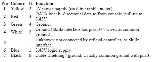
After a quick check on what was out there already about the Gamecube controller interface, I came across the int03 site which gives us the controller pin out and that it’s a serial interface which is held high to 3.4V and is pulled low.
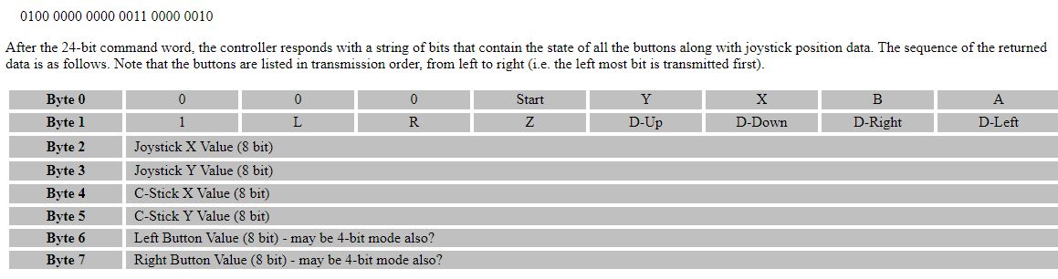
It looks like the Gamecube polls the controller which replies back with the button presses however the website mentioned that at first the Gamecube sends eight 0’s but they don’t appear to have the communication after that, how they reach the Gamecube requesting the controller state.
It looks like we’ll have to capture the initial communication with a logic analyser and also re-confirm their findings so I took apart my Gamecube controller and wired it up to take a look.
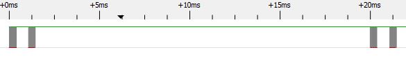
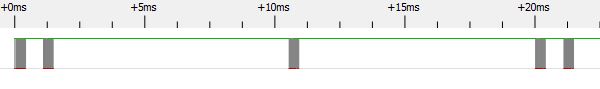
Firstly it seems like the Gamecube polls the controller at varying polling times, it may depend on whether you are in the system menu or could possibly depend on the game. We have a poll then 1ms later another poll which might be for debouncing and then 19ms after we have another 2 polls. On another instance we have the first two polls then a poll after 9ms and then the other 2 afterwards.
The first thing we need to figure out is how we will get ATmega to output data to the Gameboy because at the moment we’re currently using the ATmega to read what the Gameboy puts on the address/data lines. If we tried to read from anything at the moment, the flash chip would be the device outputting data.
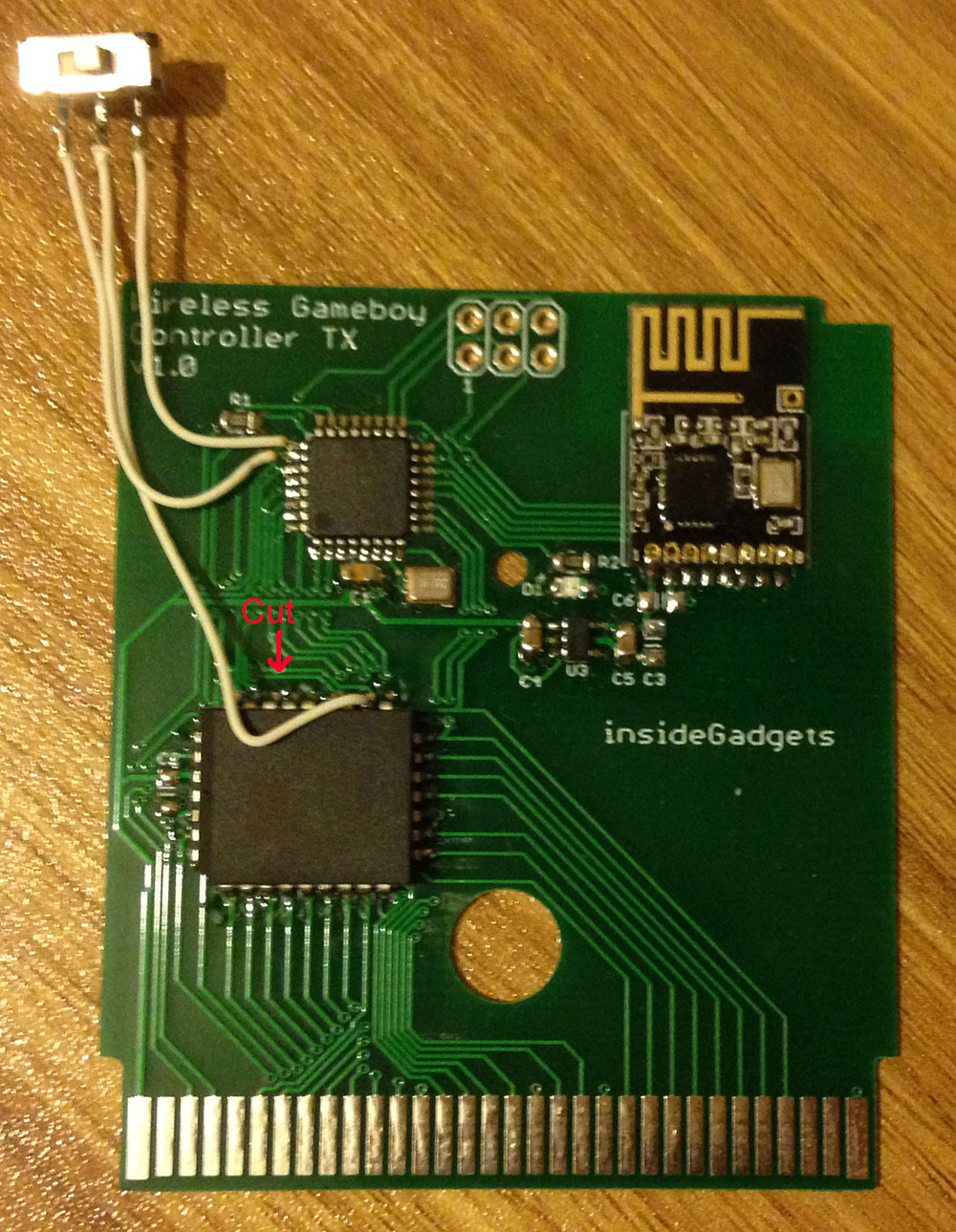
What if we cut the A15 line going into the flash chip’s CE line and change it to A14? This means that anything from 0x0000 to 0x3FFF will set the CE line active but then anything from 0x4000 to 0x7FFF will set it not active. This means that nothing will be outputting data if the Gameboy requests it, so if the ATmega can respond quickly enough, it could output data and the Gameboy would pick it up. But by doing this we are limiting ourselves to 16KB ROM size.
One problem is that the flash chip I chose uses the 0x5555 flash instructions which means we do need A15 to go to CE when flashing the chip. Not too much of an issue, I just wired up a DPDT switch for that purpose.
LD (0x7000), a
NOP
NOP
NOP

; Read data
LD E,(HL)
Let’s try to read data to see what it might look like with a logic analyser. We’ll write some data first and then try to read data.
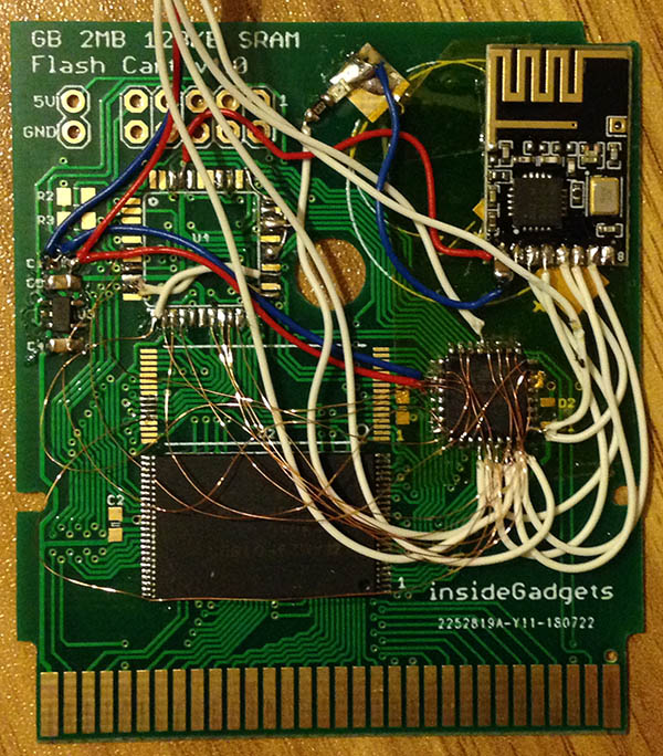
Previously we put together a Wireless Gameboy Controller using an ATmega to read the key press data which the Gameboy sent at a special address and then it was transmitted via an nRF24L01 to a USB device acting as a HID Joystick controller.
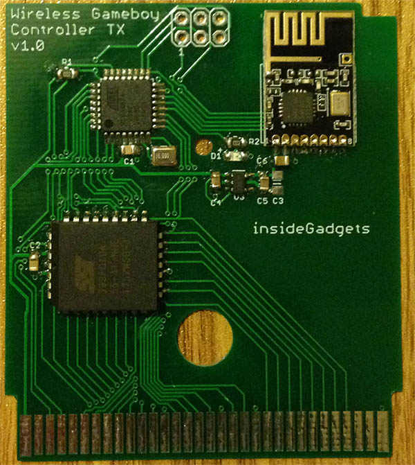
Everything worked nicely so I laid out the cartridge and USB receiver boards, sent it off, received the prototypes.
The cartridge worked first go however when putting on the top half of the case, it was a tight squeeze and was difficult to remove because the nRF module was blocking it’s path, so for the final board I’ll have to move it down a little.
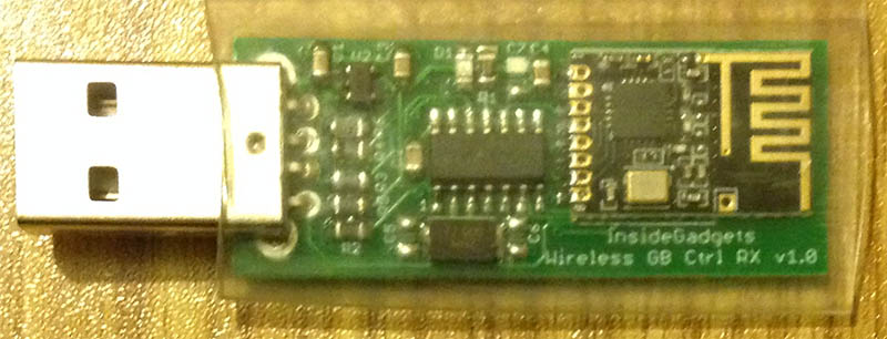
For the USB receiver, I ended up getting the nRF DO/DI pin mixed up so random data was being received. Not to worry though, I recalled that the ATtiny841 swapped the DO/DI pins for whatever reason compared to the ATtiny84. I soldered on the ATtiny841 and it all worked fine too. I’ll put some clear heat shrink over it once testing is complete.
Adding nRF24 Channel/Address configuration
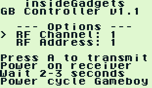
I wanted to add a method of changing and saving the nRF channel/address to the ATmega’s EEPROM so I made the GB program detect if the start button is being held down to boot into the configuration menu. We can now adjust our channel or address, this could be useful if you had multiple receivers and wanted them all to have the same address/channel or if you had some Wifi interference.
if ((readAddr & 0x1F) == 0x06) { // 0x6000 and WR low
	nrfChannel = readData;
}
// RF Address (second stage)
else if ((readAddr & 0x1F) == 0x05) { // Address 0x5000 and WR low
	PORTB |= (1<<LED);
	nrfTx[4] = readData;

	// Update our EEPROM
	eeprom_write_byte((uint8_t*) nrfChannelLocation, nrfChannel);
	eeprom_write_byte((uint8_t*) nrfTxLocation, nrfTx[4]);

	// Update the nRF settings to transmit the data to the RX
	mirf_config_setting_update();

	// Transmit the nrf setting to the receiver until powered off
	dataOut[0] = nrfChannel;
	dataOut[1] = nrfTx[4];
	while (1) {
		mirf_transmit_data(2);
		_delay_ms(50);
	}

	PORTB &= ~(1<<LED);
}
For saving this configuration to the EEPROM we need to choose a different address than 0x7000 which is used for our key presses, I went with 0x5000 for the channel and 0x6000 for the address (of which we only store the last byte of it).
In Part 6, we looked at upgrading the Multi-game feature to allow for mixing GB/GBC games by using a hardware reset on the Gameboy plus we added the ability to switch the CPLD to select MBC3 or 1 mode (MBC5 is the default) when using the loader.
One issue I wasn’t able to solve was why the GBP didn’t seem to work with the multi-game loader (it doesn’t work on the “22 in 1” cart either) so we’re going to have a look at that and also look at possibly making a new larger sized flash cart using 3.3V flash.
When trying to boot a game from the multi-game loader, we just receive a blank Nintendo logo. If I perform a manual hardware reset, it resets it back to the loader menu fine.
if (multiStage == 2'd1 && inputAddress == 4'd6) begin
  multiStage <= 2'd2; // Turn off any more multi-game bank changing
  romBankMulti <= 7'd1;
  romBank <= 7'd1;
  ramBank <= 2'b0;
  resetGB <= 1'b0; // Reset Gameboy
It felt like perhaps the bank to switch to wasn’t being set correctly, so I tried manually setting a bank in the CPLD when we triggered the reset and that worked without any issues. This leads me to believe that the GBP isn’t outputting the data fast enough in order for the CPLD to pick up the bank before it resets.
// Second stage - Check address 0x6000-6FFF for the bank to switch to
if (multiStage == 3'd1 && inputAddress == 4'd6) begin
	romBankMulti <= inputData;
end
// Third stage - Check address 0x7000-7FFF for reset
if (multiStage == 3'd2 && inputAddress == 4'd7) begin
	multiStage <= 3'd3; // Turn off any more multi-game bank changing
	romBank <= 7'd2;
        ramBank <= 2'b0;
        resetGB <= 1'b0; // Reset Gameboy
end
So after playing around for a while, I decided to switch back to executing the commands from the HRAM and adding another stage to the loader to do the reset after the multibank variable is loaded.
An idea came to me after looking at some Gameboy projects which swapped out the Gameboy PCB for their own custom board – What if we could use any Gameboy (GB, GBC, GBP, GBA, GBA SP) as a game controller, stream that over a wireless connection and use a V-USB to act as a HID keyboard or joystick. It’s now available for purchase at www.wirelessgbc.com.
It’s do-able I thought, I’ve already played around with all parts that would make this project, I just have to put it all together (and have some code I can re-use): GBDK to make the rom, either a CPLD or MCU to read the input/data, nRF24L01 or similar for the wireless and V-USB on an Atmel MCU for the joystick input. I was considering using Bluetooth as well but might as well just stick with what I know for the moment.
V-USB Joystick Interface
At first I thought about using V-USB just to output keystrokes as I had done this before with the SATVL however I quickly found that outputting and repeating a keystroke like the right cursor key, doesn’t replicate well into an emulator. Basically it’s just like the key is being pressed and released quickly, so if you wanted to move your player right, it would move them right for a little bit, then stop, move right more, etc. I tried playing around with the code but it was a no go.
I went looking to see how other users implemented their own controllers and came across the USB NES Pad adapter that uses the HID joystick interface.
In part 4, we looked at adding Multi-game support to our Gameboy cart however I’ve just recently found that we can’t play GBC games using it because the loader runs in Gameboy mode so when we jump back to 0x100 to soft reset, the Gameboy still thinks it’s in Gameboy mode.
Some GBC games like Super Mario Bros. Deluxe come up with a screen saying it can’t be run.
I tried to compare the difference in registers and I/O when starting a game in regular GB mode and GBC mode but apart from the A register and a few others if I changed those registers before trying to boot SMBD but we get some corrupted tiles.
I found that in GBDK you can also program in GBC mode, so I played around with the “Color Bar” example, removed a few parts of it so that I could print text and basically copy the loader code into it. The text looks faded but SMBD boots fine.
But a GB game like Tennis doesn’t look good, something about the palettes aren’t right. If you change register A to 0x01, it doesn’t help much either.
From our previous part, we looked at how to add Multi-game support to our cart. In this part, we’re going to switch out the 128KB SRAM for 32KB FRAM so that we no longer need a coin cell battery to keep our saves and also look at adding 2MB MBC1 ROM support; at the moment we are limited to 512KB MBC1 ROM support.
We’ll be using the Cypress 32KB FM18W08 as our FRAM chip which only costs $1-2 each from AliExpress. It has the usual CE, WE, OE lines and address/data lines like an SRAM chip does so it’s almost a drop in replacement.
The one thing that datasheet mentioned compared to SRAM is that the CE line needs to be strobed when you change the address, mainly due to the fact that the memory access needs a pre-charge which is performed when CE goes high for a certain amount of time.
When you read data from the memory cells to the internal buffer, the data from the memory cells is lost until you write it back, this is what the pre-charge is for (odd name for it), it writes the data from internal buffer to back to the memory cells so it’s a good idea to have a pull-up on the CE line (which I do already have). More information on F-RAM pre-charging can be found here.
With that out of the way, I built up another Gameboy cart, glued down the FRAM chip and wired it up.
From our previous part, the PCBs arrived and I started testing games. There were a few that didn’t work and was able to get some to work by adding some MBC1 support via a few little detection hacks. This part, we’ll look at how to add Multi-game support plus use GBDK to create our game selection screen loader.
(sneak peak of loader screen)
Multi-game support is pretty useful if you have a lot of little games that are 32-256KB but don’t want to have a cart just for each of them. They might also be games that don’t need to save because it can be very easy to load the wrong game and it could potentially overwrite the SRAM.
The way multi-game support works is once you select a game, it send either the bank or the memory location of the game to the custom MBC via an address that wouldn’t likely be written to, the ROM bank is changed, the Gameboy is soft reset and then the game loads.
reg [6:0] romBankMulti;
...
romBankMulti <= 7'd2;
...

// *** ROM Functions ***
if (inputAddress <= 4'd7 && (!inputRD || !inputWR)) begin
	if (inputAddress <= 4'd3) begin // 0x0000-3FFF, Bank 0 always
		highAddress <= romBankMulti << 1;
	end
	else begin
		highAddress <= ((romBank + romBankMulti) << 1);
	end
end
Just to test the concept, we can append one 32KB game to another 32KB game, flash it to the cart and then add a rom bank adjustment variable for multi-carts. If we change the variable to be 2, it will select bank 2 of the flash chip when the Gameboy asks for bank 0. When it asks for bank 1, we simply add the romBankMulti variable to the rom bank the Gameboy asked for; we are always adjusting the rom bank to be 2 banks higher than what it asks for in this case.
Now we just need to make that rom bank adjustment variable configurable so what’s the best address for us to send the bank command to our CPLD? We also need to consider that users may not use the multi-game loader so it shouldn’t conflict with normal cart operation.
From our previous part, we added the SRAM and tested the battery backup was working correctly. In this part, I was hoping to look into the FRAM but instead when the PCBs arrived, I started testing games, found a few that didn’t work and was able to get some to work by adding some MBC1 support via a few little detection hacks.
I was laying out the PCB, was almost done, then I looked at an actual cart and realised there was a hole in the board, this screw hole would go straight through the ROM. I didn’t want to re-layout the board having already spent hours on it but happened to notice that some clone carts had the hole at the top. After moving the CPLD a little bit, it worked out fine.
The prototype HASL PCBs arrived a little while later, they sort of fit the cart but I’ll need to move the screw hole down just a tad. At the time, I didn’t have any CR2025 SMD tabbed batteries so I just put in a through-hole coin cell holder. You might also notice that the board is quite thick; I didn’t measure the thickness and left it as 1.6mm when it’s really 0.8mm. Another little issue is that R1/R2 resistors are too close to the bottom of the board, so I’ll move them up. I brought out the clock and audio in lines to the CPLD just in case I ever wanted to play around with those.
Little problems aside, the PCB worked well, loaded up a couple games and played them without any issues so I made the little changes to the PCB and had it done with ENIG, gold fingers with a 45 degree bevel and ordered 50 of them.
Current consumption
I wanted to see how much current the cart was taking compared to other carts so I measured the current of the whole GBA – running Pokemon Silver start screen it was reading 139/141mA while regular carts were 83mA. It’s quite a bit actually but most of it is due to the CPLD (even unprogrammed ones draw 30mA!).
In the last part, we looked at 3 DC-DC step down converters, tested their quiescent current and efficiency but none really stood out in both aspects. Near the end, we came up with a solution to which keeps the DC-DC in shutdown and only enables it when the GBA power switch is flicked on. In this part, we’ll continue to test this solution, look at how to detect low battery, order some boards and check the performance.
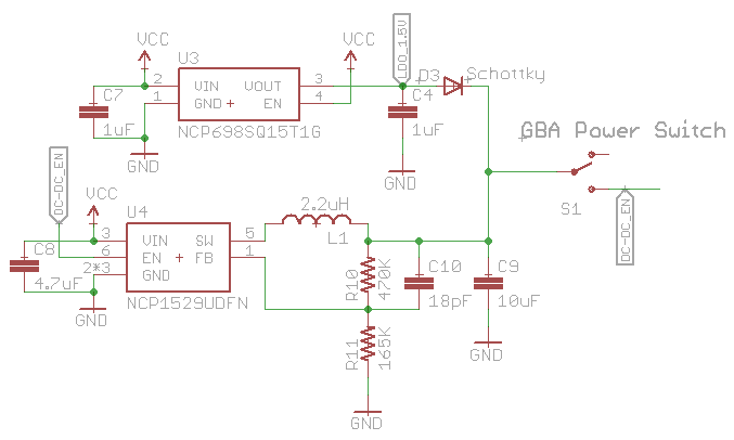
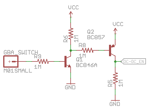
Here’s a schematic to show how the solution works, you can see the LDO’s output goes through the diode and is tied to the DC-DC output. The DC-DC enable pin is tied to the other side of the switch and would normally be off. Once the switch is flicked, the LDO output voltage reaches the DC-DC enable pin and switches the DC-DC on.
Previously I was using a 1.8V LDO I had laying around for testing so I ordered an ultra low quiescent current LDO, the NCP698 which has a quiescent current of 6uA maximum. The 1.8V version was 20c more expensive than the 1.5V variant so I went with the 1.5V one instead as it should still work fine. We don’t want to have too high of a voltage, otherwise the LDO would be powering the GBA instead of the DC-DC.
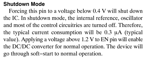
When testing it out, it looked like the output after the diode was 1.33V when the GBA was trying to turn on but the DC-DC wouldn’t turn on, even though the datasheet said the voltage above 1.2V should be enough. I hooked up the LDO voltage to the enable pin directly and it did switch on fine.
Potentially this could have also happened with the 1.8V variant as well so I wanted to find a way to switch the enable pin to VCC instead of the LDO’s output. After a bit of testing, we can use a NPN with a PNP for our solution, resistors are high value ones so that current consumption is kept low but it only draws current (12uA) when the GBA is on. By default, the NPN is off so the PNP is also off and thus the output is 0. Once the power is flicked on, all we need is at least 0.7V on the NPN so it switches on, the PNP base will then be close to 0V and that will switch on, which means VCC will reach the DC-DC enable pin.
AdvanceVGA – Play your GBA on the big screen! Swap out the LCD for our board, solder some wires, connect 5V USB and VGA and you’re ready to go.
GBxCart RW allows you to backup GB/GBC/GBA ROMs, save or restore game saves and re-write supported flash carts. Mini RW option available for GB/GBC only.
Wireless Gameboy Controller – Use your Gameboy, mGB, GBC, GBA, GBA SP, GB Micro, NDS and NDS Lite as a wireless controller on Windows, Linux, Raspberry Pi, etc, and on your NES, SNES, N64, Gamecube and Wii.