|
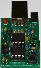
insideGadgets Standalone
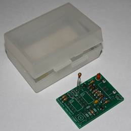
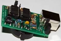
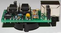
Temperature/Voltage Logger v1.x Kit A standalone temperature/voltage logger in a small compact form factor with minimal parts using the ATtiny85 and an external I2C EEPROM powered by a 3V coin cell. Data logged can be extracted to a computer with a USB cable. The standalone temperature/voltage logger uses V-USB: http://www.obdev.at/vusb/ |
|
Features
- Low power consumption, at least 1 year battery life
- Measure temperature from -40C to 125C saving to EEPROM as 8 bit (as 1 byte) or 10 bit (as 2 bytes).
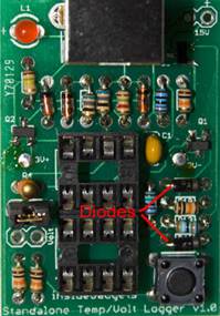
- Measure voltage from 0V to 15V saving to EEPROM as 8 bit (as 1 byte) or 9 bit (as 2 bytes). (Voltage range can be increased if the 2 voltage protection diodes are removed and the code is modified)
- Uses an external I2C EEPROM, supports up to 512Kbit which is 65,536 recordings (with 1 byte values) or 32,768 (with 2 byte values)
- 12 logging delay times available (28secs, 1min, 5mins, 10mins, 15mins, 30mins, 1hr, 2hrs, 4hrs, 8hrs, 12hrs, 24hrs)
- Easily transfer the logged data to your PC via USB. Fimware 1.0.x will print out the data logged one result at a time so you will need to have notepad (or any other program) open until all the data is transferred. With firmware 1.1+ you run a program to transfer the data.
Note: You can only log temperature or voltage, not both at the same time. No information on time is recorded when logging.
Specifications
PCB Board: 41mm x 28.5mm
Voltage: 2.7V to 5.5V
Current used when sleeping: 5uA
Current used when logging - Watchdog sleep routine: 0.3mA for 30ms approximately every 4 seconds
Current used when logging - Thermistor on, LED on and write to EEPROM: 3mA (max) for 50ms
Resolution of temperature (1 byte): 0.65C (rounded up or down in 0.5 - 1C increments)
Resolution of temperature (2 bytes): 0.16C (rounded up or down in 0.2C increments)
Resolution of voltage (1 byte): 0.06V
Resolution of voltage (2 bytes): 0.03V
Accuracy of Thermistor: within 5% -/+ (between -40C to 25C is 1.25C -/+, 25C to 50C is 1.5C -/+, 50C - 70C+ is 1.9C -/+)
Accuracy of timer: within 10% -/+
Operating temperature: -40C to 125C (Most CR2032 batteries only support -40C to 70C)
Kit Contents
To assemble the kit you will require a soldering iron and solder.
To use the kit you will require a 3V CR2032 coin cell and a 1Kbit-512Kbit I2C EEPROM (which can be purchased when you purchase this kit).
To extract the data you will require a USB type A to B cable (commonly used for connecting printers).
Standard Kit includes (for
temperature logging)
|
Picture |
Name |
Description |
Qty |
|
|
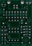
PCB |
Standalone Temperature-Voltage Logger v1.1 PCB Pre-soldered SMD components: N Channel Mosfet SOT23 (1) - 2N7002K - [Q1, Q3] P Channel Mosfet SOT23 (1) - BSS84 - [Q2] |
1 |
|
|
U1 |
ATtiny85 20MHz DIP8 - ATTINY85-20PU (Pre-programmed) |
1 |
|
|
U2 |
EEPROM (BYO, can also be purchased when you purchase this kit. Needs to be 2.7V to 5.5V) |
1 |
|
|
R5, R6 |
68R Resistor 1/8W (Blue, gray, black, gold) |
2 |
|
|
R8 |
1.5K Resistor 1/8W (Brown, green, red, gold) |
1 |
|
|
R1, R2, R9, R10 |
10K Resistor 1/8W (Brown, black, orange, gold) |
4 |
|
|
R3 |
10K Resistor 1/8W 1% (Brown, black, black, red, brown) |
1 |
|
|
R7 |
150K Resistor 1/8W (Brown, green, yellow, gold) |
1 |
|
|
R4 |
10K Thermistor - NTCLE100E3103JB0 |
1 |
|
|
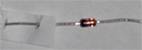
D1, D2 |
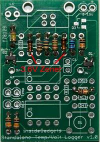
Zener Diode 3.6V 1/2W DO-35 - 1N5227B |
2 |
|
|
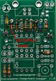
D3 |
Schottky Diode 400mV[VF Max] DO-35 - BAT42 (Notice the white paper on the left lead) |
1 |
|
|
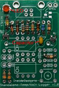
C1 |
0.1uF Capacitor |
1 |
|
|
L1 |
3mm Red LED - MCL514SRD |
1 |
|
|
S1 |
4.3mm Tactile switch - MJTP1230 |
1 |
|
|
ICSOCKET |
8 pin IC socket |
2 |
|
|
MALEHEADER |
2 pin male header |
1 |
|
|
SHORTBLOCK |
Shorting block |
1 |
|
|
BATHOLD |
Coin cell battery holder |
1 |
|
|
USB |
USB Type B Receptacle - USB-B-S-RA |
1 |


Voltage Add-on Kit includes (to add on
voltage logging)
|
Picture |
Name |
Description |
Qty |
|
|
R11 |
15K Resistor 1/8W 1% (Brown, green, black, red, brown) |
1 |
|
|
R12 |
390K Resistor 1/8W 1% (Orange, white, black, orange, brown) |
1 |
|
|
D4, D5 |
Diode 680mV VF @ 1mA DO-35 - FDH300A |
2 |
|
|
FEMALEHEADER |
2 pin female header |
1 |
|
|
MALEHEADER |
2 pin male header |
1 |
Step by Step Instructions
1. Install the 9 resistors – 68R (R5, R6), 1.5K (R8), 10K (R1, R2, R9, R10), 10K 1% (R3) and 150K (R7)
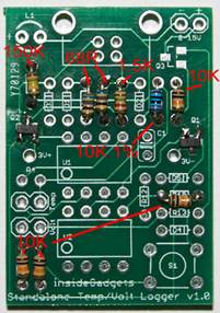
2. Install the two 3.6V Zener diodes (D1, D2), notice the orientation.
3. Install the Schottky diode (D3) - it has a white paper on one of the leads, notice the orientation.
4. Install the LED (L1) and capacitor (C1). The longer lead of the LED should go on the + pad.
5. Install the thermistor (R4).
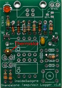
You can also choose to solder the thermistor with the leads intact so you can place the PCB in a small container and the thermistor’s top would be located outside the container. You can also solder wires to position the thermistor elsewhere.
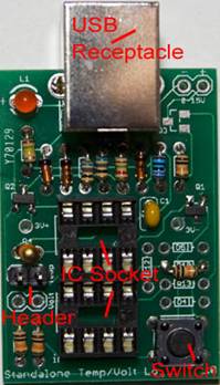
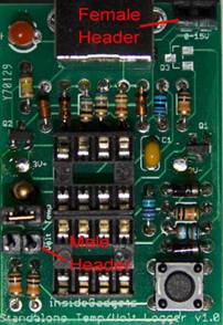
6. Install the IC sockets (on U1 and U2), switch (S1), male header (on Temp) and USB receptacle (USB).
7. Before
you install the coin cell battery holder (BATHOLD) on the back, if you
purchased the Voltage Add-on Kit please skip to the “Voltage Add-on Kit - Step
by Step Instructions" section.
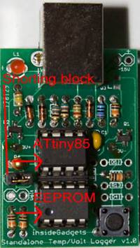
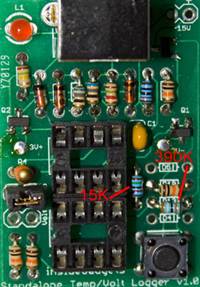
8. Install the ATtiny85 (on U1) and the EEPROM (on U2). Notice the small circles (where the arrows point to) on each device and how they are mounted. Install the shorting block on the male header.
9. (Optional) You will notice that the Standalone Temperature/Voltage Logger leans to one side once placed in a flat surface.
You can adjust this by cutting a small piece of the foam that came with the ATtiny85 and gluing it underneath the USB receptacle.
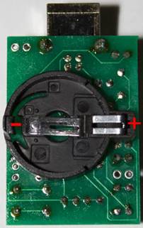
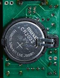
10. Install the battery with positive side facing outwards. The kit has now been assembled, please read the “How to use - First time use” section.
Voltage Add-on Kit - Step by Step Instructions
1. Install the 2 resistors – 15K (R12) and 390K (R13)
2. Install the diodes (D4, D5), notice the orientation.
3. Install the male header (on Volt) and the female header (on 0-15V).
4. Continue with the “Step by Step Instructions” step 7.
Programming the ATtiny85 (optional)
This step is only necessary if you wish to update the firmware on the ATtiny85 or if you have replaced the ATtiny85. You will require a programmer such as the USBtinyISP and your programmer will need to be supported by the software called AVRDUDE.
To program the ATtiny85 and fuse bits we use the AVRDUDE software: http://savannah.nongnu.org/projects/avrdude/
1. Change the fuse bits so the ATtiny85 uses 16MHz PLL and divide clock by 8 by running the following command:
avrdude –p ATtiny85 –c usbtiny –U lfuse:w:0x61:m –U hfuse:w:0xdf:m –U ffuse:w:0xff:m
Note: You can select to add a Brown-out Detection of 2.7V however it is optional (replace “-U hfuse:w:0xdf:m” in the above line with “-U hfuse:w:0xdd:m”) and is only recommended for CR2032 batteries that are new or near new condition. When batteries drop to 2.95V or thereabouts there may be issues when powering up the ATtiny85.
2. Upload the main.hex file to the ATtiny85 by running the following command:
avrdude –p ATtiny85 –c usbtiny –U flash:w:main.hex
How to Use
Inserting or removing the ATtiny85/EEPROM
You should only insert or remove the ATtiny85/EEPROM when the battery has been removed.
First time use
1. Insert the ATtiny85 and EEPROM.
2. Insert the battery.
3. The LED will either blink to indicate there is an EEPROM present or it will stay on for 2 seconds to indicate that no EEPROM was found.
The number of blinks corresponds to the EEPROM size that was found as shown below.
|
Blinks |
EEPROM size |
Max recordings (1
byte) |
Max recordings (2
bytes) |
|
1 |
1 Kbit |
128 |
64 |
|
2 |
2 Kbit |
256 |
128 |
|
3 |
4 Kbit |
512 |
256 |
|
4 |
8 Kbit |
1,024 |
512 |
|
5 |
16 Kbit |
2,048 |
1,024 |
|
6 |
32 Kbit |
4,096 |
2,048 |
|
7 |
64 Kbit |
8,192 |
4,096 |
|
8 |
128 Kbit |
16,384 |
8,192 |
|
9 |
256 Kbit |
32,768 |
16,384 |
|
10 |
512 Kbit |
65,536 |
32,768 |
4. Configure the logging time interval.
4a. Hold the button down for 3 seconds then let go, the LED will stay on for 2 seconds to confirm you are changing the logging time.
4b. Configure the logging time interval by pressing the button the amount of times shown below. Please wait for the LED to light up to confirm each button press.
|
Button presses |
Logging time
interval |
|
1 |
28 seconds |
|
2 |
1 minute |
|
3 |
5 minutes |
|
4 |
10 minutes |
|
5 |
15 minutes |
|
6 |
30 minutes |
|
7 |
1 hour |
|
8 |
2 hours |
|
9 |
4 hours |
|
10 |
8 hours |
|
11 |
12 hours |
|
12 |
24 hours |
(The time interval accuracy is within 10% -/+)
4c. Hold down the button for 1 second to confirm your logging time interval, the LED will blink three times to confirm. (If the LED stays on for 2 seconds too many button presses were made, please repeat step 4b)
5. Configure the function to use.
5a. On the PCB there are 2 connectors, one called “Temp” for temperature and another called “Volt” for voltage. Use the shorting block (jumper) on the connector whose function you wish to use and leave it in place when you start logging temperature or voltage.
5b. Hold the button down for 5 seconds, the LED will stay on for 4 seconds to confirm you are changing the function to use.
5c. Configure the function to use by pressing the button the amount of times shown below. Please wait for the LED to light up to confirm each button press.
|
Button presses |
Function |
|
1 |
Temperature logging (using 1 byte) |
|
2 |
Temperature logging (using 2 bytes) |
|
3 |
Voltage logging (using 1 byte) |
|
4 |
Voltage logging (using 2 bytes) |
5d. Hold the button down for 1 second to confirm the function to use, the LED will blink three times to confirm.
Warning: Failure to change the shorting block (jumper) to cover the “Volt” connector when using voltage logging will damage the ATtiny85.
6. Ready to start logging.
Start temperature/voltage logging
1. Press the button 3 times within 2 seconds to activate the temperature/voltage logging. The LED will blink three times to confirm. The LED will blink very quickly every time it logs a reading.
If the LED stays on for 2 seconds this means that no external EEPROM was found. You will need an external EEPROM to be able to log data.
Exit temperature/voltage logging
Press the button once and the LED will blink 2 times.
Transfer data logged to your PC
1. Plug the USB cable into the Standalone Temperature/Voltage Logger. If no battery is inserted the LED may blink a number of times as shown in “How to Use - First time use” step 3. It is normal for you to receive a “USB device not recognised” message.
For Firmware 1.1+
2. Press the button once.
3. Run the satvltransfer program found in the SATVL_v1.1\satvltransfer folder to transfer the data to a file. The filename that will be create is: <year>-<month>-<day>_<hour>-<minute>-<second>.txt
For Firmware 1.0.x
2. Open Notepad, Excel or any other program.
3. Press the button once. The data logged will be printed via an emulated keyboard one result at a time.
4. The LED will stay on or blink until the data transfer is complete. Once the LED is off, unplug the USB cable.
If you remove the USB cable mid-way through the data transfer and find the LED is still lit, please remove and re-insert the battery.
Test the USB communication
1. Remove the EEPROM and battery
2. Follow the "Transfer data logged to your PC" steps
3. The
number "124.5", "0" or “14.98” will be printed until the
USB cable is disconnected.
Errata (v1.0 PCB)
1. In the parts list you will notice R11 is missing, there is no R11 part.
2. Q3 was designed for a Mosfet however there was a design flaw which resulted in the voltage always reading 50mV if the external voltage source was more than 1.4 volts. To correct this issue a bridge was made between the drain and source on the PCB. This means there will always be a load of 405K Ohms on the external voltage source. The original design was to have the Mosfet switch the load on when a voltage reading was taking place and then off once it was done.
Revision History
Rev. 6 – 1/10/2012
· Updated R12 (15K) to be R11 and R13 (390K) to be R12
Rev. 5 – 12/08/2012
· Split up “Transfer data logged to your PC” section into 2 parts – firmware 1.1.x and firmware 1.0.x
· Updated “Errata” section to apply only to v1.0 PCB
Rev. 4 – 4/08/2012
· Small changes to some sentences
Rev. 3 – 7/07/2012
· Added time interval accuracy to logging time interval table
· Updated “How To Use” section 5a
Rev. 2 – 11/06/2012
· Updated “Feature” notes
· Updated “How To Use” guide
Rev. 1 – 13/04/2012
· Initial Revision
(c) 2011-2012 by insideGadgets
This work is licensed under a Creative Commons Attribution-NonCommercial 3.0 Unported License.