Standalone Voltage Logger
Nov 13th, 2011 by Alex
The Standalone Voltage Logger has been merged with the Standalone Temperature Logger to give the Standalone Temperature/Voltage Logger available in kit form.
A standalone voltage logger in a small compact form factor with minimal parts using the ATtiny85 and powered by a 3V coin cell. Based on the Standalone Temperature Logger. Extract the data logged by connecting to your PC using a USB cable. The standalone voltage logger uses V-USB – http://www.obdev.at/vusb/.
Features
– Low power consumption, at least 1 year battery life
– Store up to 255 voltage readings
– 11 logging delay times available (1min, 5mins, 10mins, 15mins, 30mins, 1hr, 2hrs, 4hrs, 8hrs, 12hrs, 24hrs)
– Easily transfer the logged data to your PC via USB
Specifications
PCB Board: 35mm x 28mm
Voltage: 2.7V to 5.5V
Current used when sleeping: 5uA (When logging, jumps to 0.3mA for ~30ms approximately every 4 seconds)
Accuracy of timer: within 10% -/+
Operating temperature: -40C to 70C
Download
v1.1 (8 November 2011) – Download
– Updated to include capacitor, 2 over-voltage protection diodes replaced for a DO-35 type and replaced 39K/1.5K resistors with 390K/15K
– Added PCB Etching
– Fixed bug when configuring delay time. If button was held down before any delay time was set, nothing would happen
v1.0 (5 November 2011) – Download
– Initial Release
Sample Data
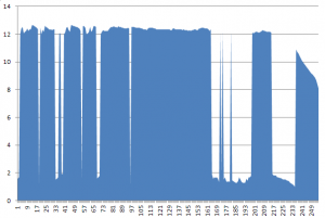
Y axis is the voltage and X axis is each interval.
Measuring solar panel – 1 minute intervals
Programming the ATtiny85
To program the ATtiny85 and fuse bits we use AVRDUDE
- Change the fuse bits so the ATtiny85 uses 16MHz PLL and divide clock by 8
avrdude -p ATtiny85 -c usbtiny -U lfuse:w:0x61:m -U hfuse:w:0xdf:m -U efuse:w:0xff:m2.7V Brown-out Detection is optional (-U hfuse:w:0xdd:m) and is only recommended for CR2032 batteries that are new or near new condition. When batteries drop to ~2.95V there may be issues when powering up the ATtiny85. - Upload the main.hex file
avrdude -p ATtiny85 -c usbtiny -U flash:w:main.hex
How to use
Changing logging time intervals
- Hold the button down for 2 seconds, the LED will stay on for 2 seconds to confirm you are changing the logging time.
- Configure the logging time interval by pressing the button the amount of times shown below.
1 button press = 1 minute
2 button presses = 5 minutes
3 button presses = 10 minutes
4 button presses = 15 minutes
5 button presses = 30 minutes
6 button presses = 1 hour
7 button presses = 2 hours
8 button presses = 4 hours
9 button presses = 8 hours
10 button presses = 12 hours
11 button presses = 24 hours - Hold the button down for 1 second to confirm your logging time interval, the LED will blink three times to confirm.
(If the LED stays on for 2 seconds too many button presses were made, please repeat step 2)
Start voltage logging
- Press the button 3 times in 2 seconds to activate the voltage logging. The LED will blink three times to confirm. The LED will blink very quickly every time it logs the voltage.
Exit voltage logging
- Press the button once and the LED will blink 2 times.
Transfer the data to the PC
- Plug the USB cable into the Standalone Voltage Logger
- Open Notepad
- Press the button once. The LED will stay on until the data transfer is complete.
- Unplug the USB cable
Test the USB communication
- Program the ATtiny85
- Follow “Transfer the data to the PC” steps
- The number “0.0” should be printed 255 times
Build your own
Parts Required
– ATtiny85 20MHz DIP8 (1) – ATTINY85-20PU – [U1]
– N Channel Mosfet 1.5V[Threshold Vgs Typ] SOT23 (1) – BSS138 – [Q1]
– P Channel Mosfet -1.7V[Threshold Vgs Typ] SOT23 (1) – BSS84 – [Q2]
– 68R Resistor 1/8W (2) – [R5, R6]
– 1.5K Resistor 1/8W (1) – [R8]
– 10K Resistor 1/8W (3) – [R1, R2, R9]
– 15K Resistor 1/8W (1) – [R3]
– 100K Resistor 1/8W (1) – [R7]
– 390K Resistor 1/8W (1) – [R4]
– 0.1uF Capacitor (1) – [C1]
– Zener Diode 3.6V 1/2W DO-35 (2) – 1N5227B – [D1, D2]
– Schottky Diode 400mV[VF Max] DO-35 (1) – BAT42 – [D3]
– Diode 680mV VF @ 1mA DO-35 (2) – FDH300A – [D4, D5] – (has not been tested)
– 3mm Red LED (1) – MCL514SRD – [L1]
– 4.3mm Tactile switch (1) – MJTP1230 – [S1]
– 8 pin IC socket (1)
– 3V CR2032 coin cell (1)
– Coin cell battery holder (1)
– Male headers (2)
– USB Type B Receptacle (1) – USB-B-S-RA – [USB]
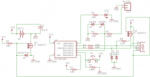
Schematic
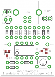
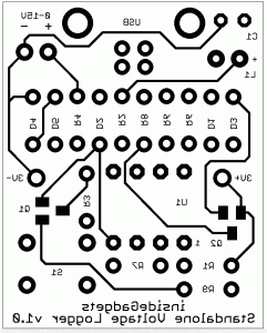
PCB Guide
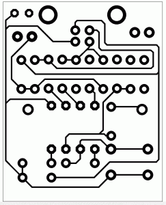
PCB Ready for etching

This work is licensed under a Creative Commons Attribution-NonCommercial 3.0 Unported License.
