Posted in Teardowns on Aug 22nd, 2015
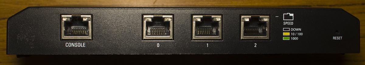
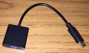
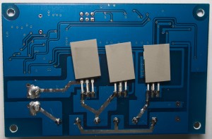
Just a quick one today, we’re looking at a generic DisplayPort to VGA Adapter that was reported faulty by an end user, I believe it was lines on the screen/flicking or similar.
We easily pop out the covers on each end.

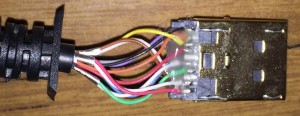
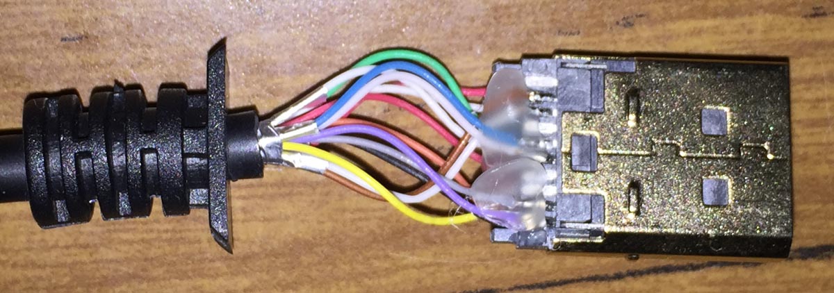
The DisplayPort connector is directly wired and glued, not too bad.
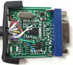
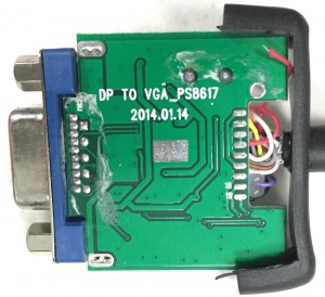
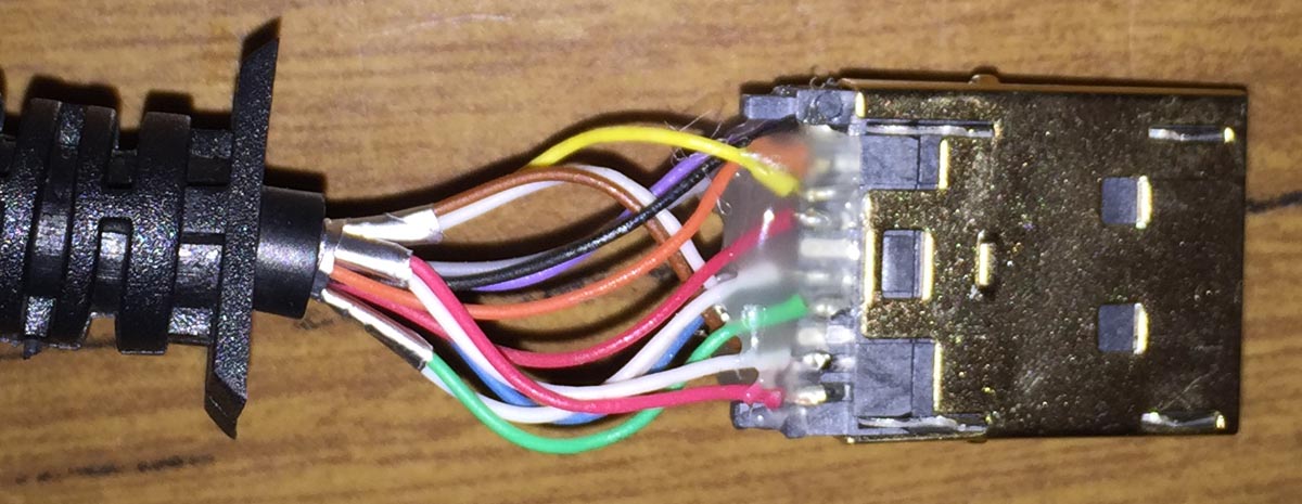
For the VGA side, we have the PCB with 2 chips but also have 5 wires just dangling around, that can’t be good. PCB Date is 14th January 2014.
(more…)
Read Full Post »
Posted in Teardowns on Aug 17th, 2015
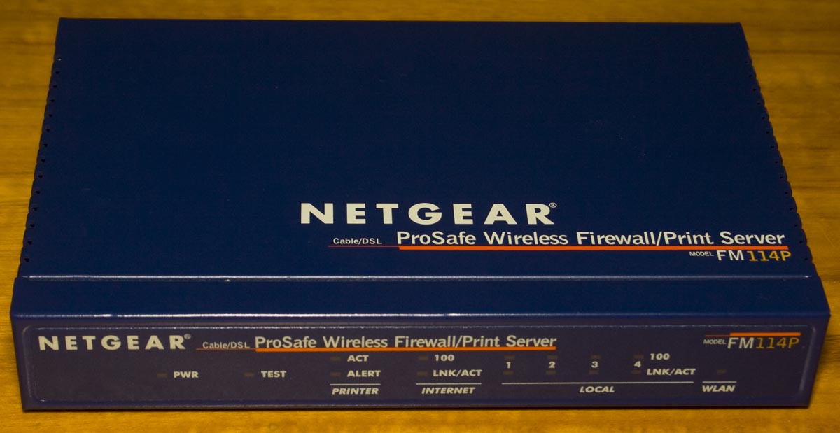
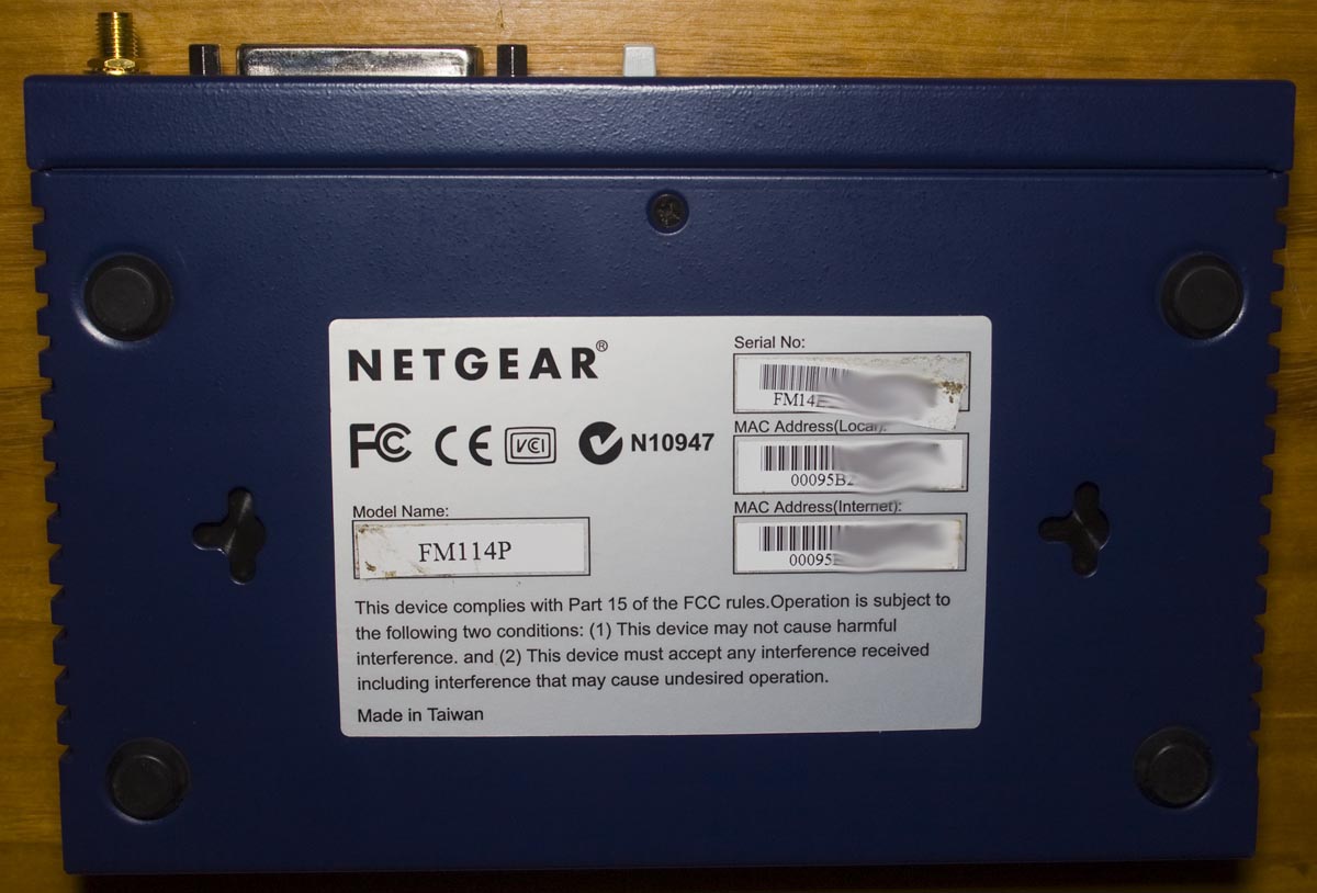
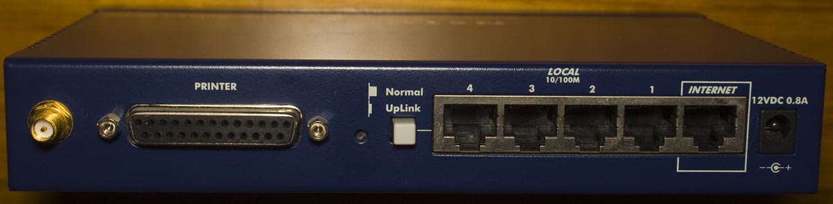
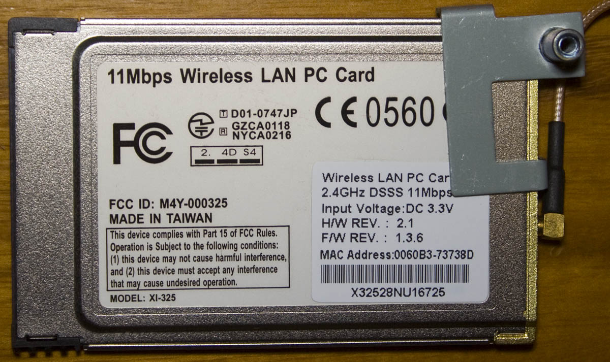
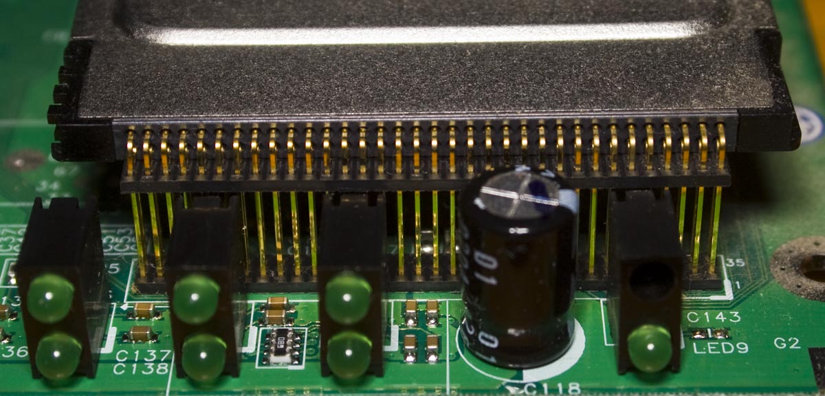
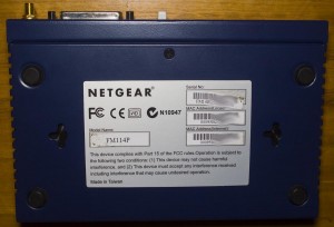
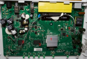
Today we’ll be taking a look at an old device the Netgear ProSafe Wireless Firewall/Print Server (FM114P), it’s a 11Mbps 802.11b parallel print server / access point with 4x 10/100 network ports and 1x 10/100 WAN port.


One screw later and we’re in.
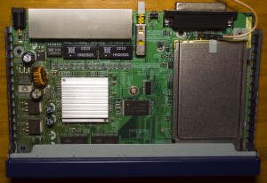
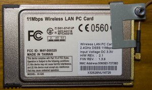
We’ve quite a bit of logic chips under the wireless card and a small heatsink for the processor and an 802.11b Wireless PCMCIA card (XI-325) connected via some right angle pin headers – they may not have had enough room to fit it in or it was easier to buy it off the shelf than design it themselves. For power side of things, we have a LM2576 SMPS and 2x 1084CM linear regulators. PCB date of 35th week, 2002.
(more…)
Read Full Post »
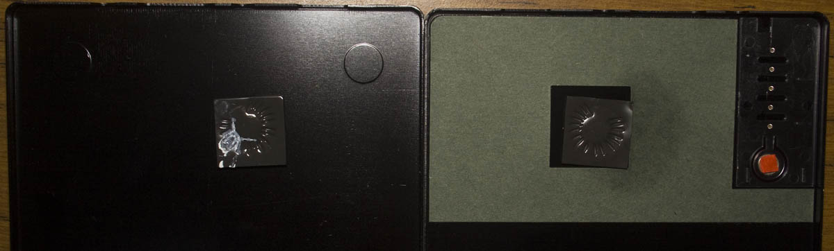
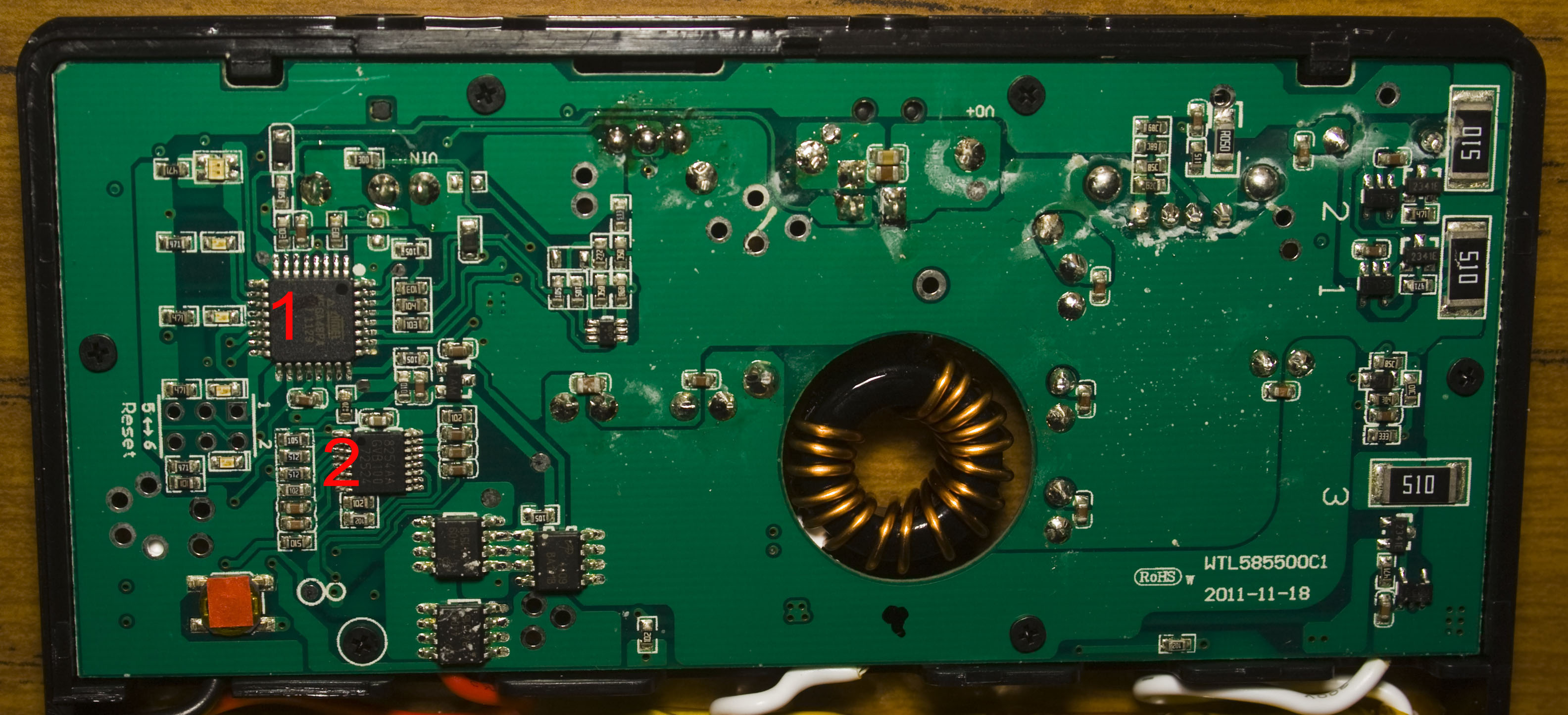
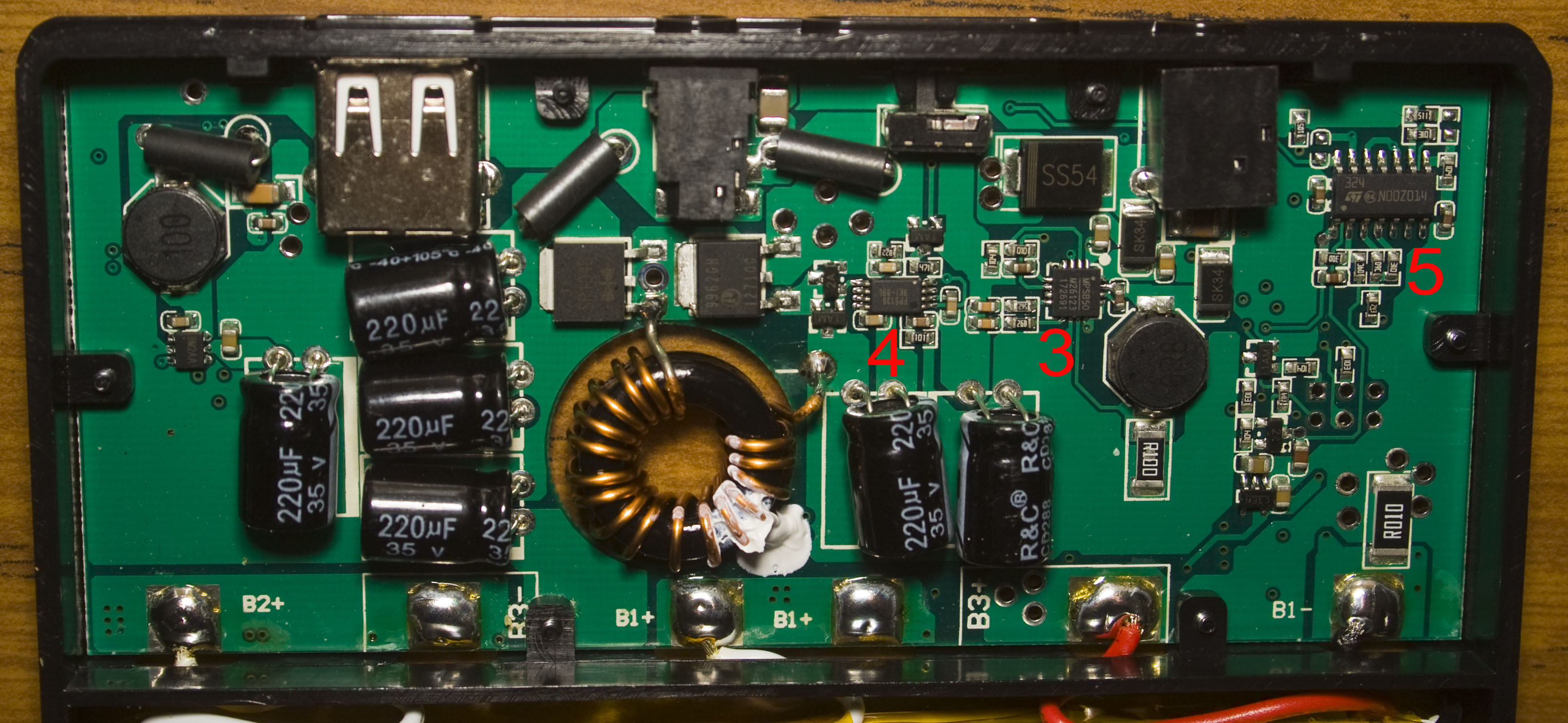
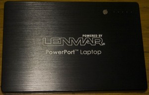
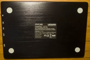
Posted in Teardowns on Jul 14th, 2015
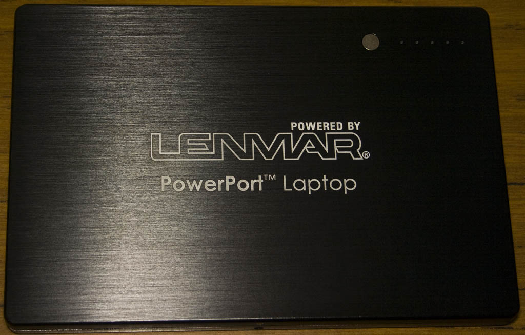
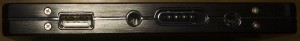
Today we’ll be taking a look at the Lenmar PowerPort Universal Laptop Power Pack, it’s a power pack to provide power to your laptop or device, it outputs 16V/19V and 5V at 1amp and an input plug accepts your laptop’s charger to charge the Lipo 11.1V / 5500mAh battery. To use the device, you connect your load and press the button which switches the load on.
A lot of little screws later and we’re in.
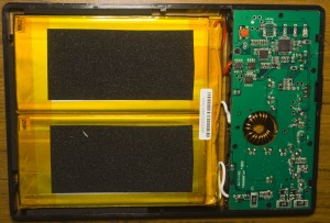
We have 6x 3.7V 2865mAh batteries with each pair of batteries wired in parallel to give us a 3 cell battery and there’s some adhesive on the case for the inductor to keep that from moving around. PCB date code is Nov 2011.

There’s quite a lot of components, more than I thought would be in it and I didn’t expect to see an ATmega as the MCU. An 0.01 ohm sense resistor at battery1 ground helps to sense current flow so when the button is pressed, the LEDs turn on for a few seconds and if a voltage drop is detected due to having a load connected then it keeps supplying power otherwise after the LEDs turn off, it switches off power. We have 6x R&C branded 220uF capacitors and a 51 ohm resistor with a small 6 pin chip for each battery, I’m guessing it may be some part charge/discharge controller/balancer.
(more…)
Read Full Post »
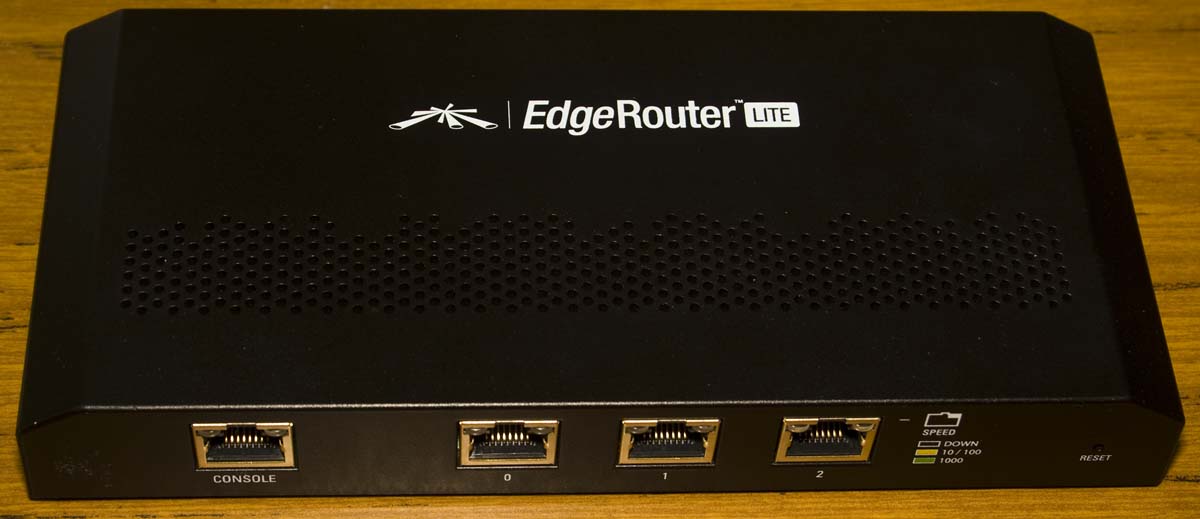
Posted in Teardowns on Jun 10th, 2015
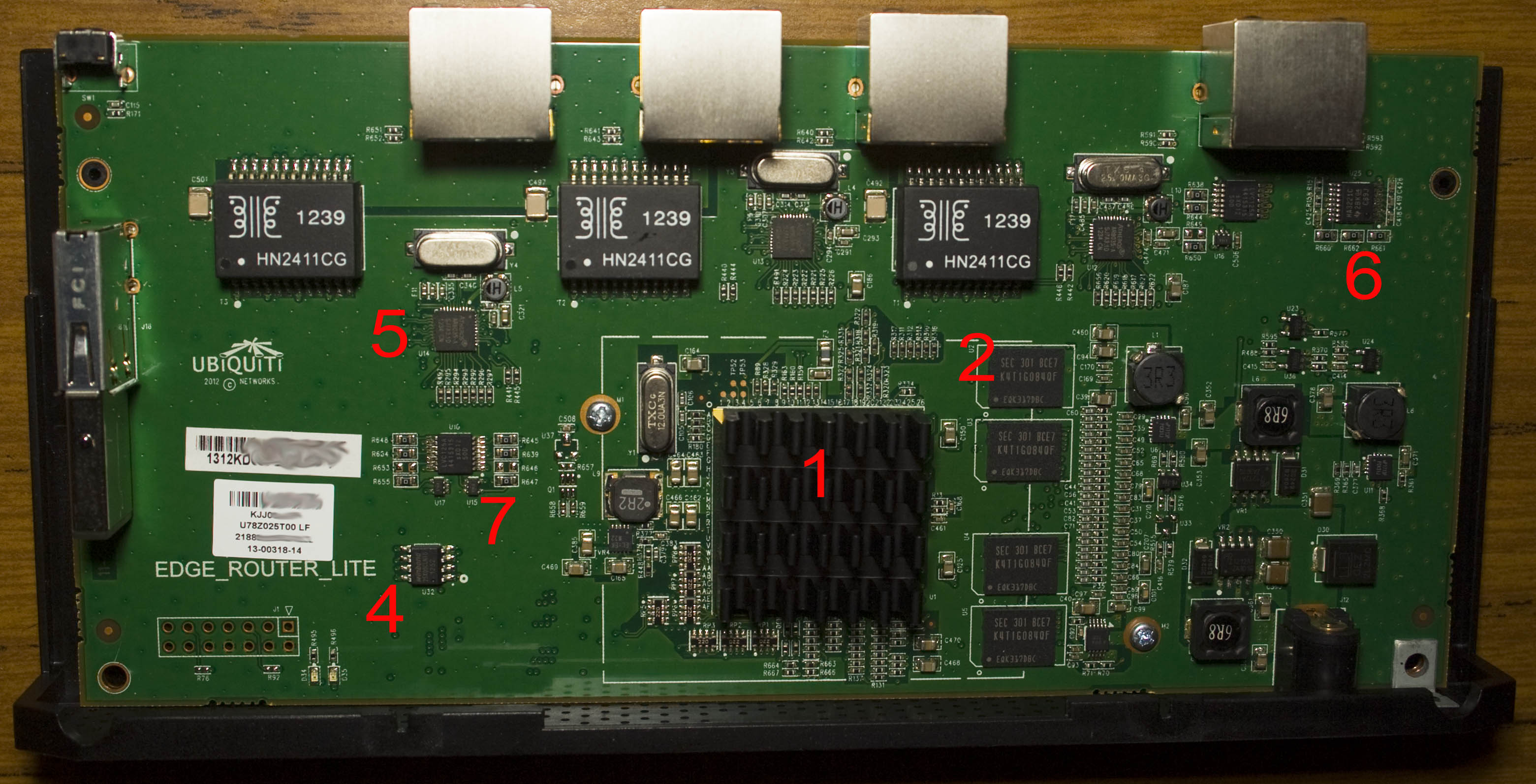
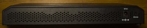
Today we’ll be taking a look at a Vyatta/linux based modern router, the Ubiquiti EdgeRouter Lite which is a WAN router with 3x 10/100/1000 configurable network ports and a console port. It has a webpage for management but most of the configuration happens using the console / SSH so not something that home users would use. This particular unit has a “squash fs” problem near the end of the boot (it still boots ok) and also when trying to save the configuration which isn’t the first time it’s happened with these older model EdgeRouters, the errors could be coming from the USB or flash memory.

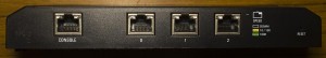
A few screws later and we’re in and there were no tamper protection seals.
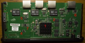
We’ve got a main processor, 4 Gigabits of RAM, 32Mbit of flash, a 4GB USB dongle (split into 142MB FAT / 1.63GB unknown partition, the rest free space) and separate PHYs/transformers for each network port, it must have been more cost efficient to have 3x PHYs that use a processor that had them all built in. The line up of capacitors near the center looks neat and there’s a 7×2 pin header near the bottom left unpopulated. There are 2x Alpha & Omega Z1212AI, 2x uP1713P and 1x EL-EK22 DC-DC converters. PCB date code is 4th week of 2013.
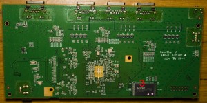
On the bottom side, they’ve left the copper exposed underneath the processor which joins up with the heatsink they have on the bottom and is screwed in place, that’s a nice solution.
(more…)
Read Full Post »
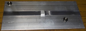
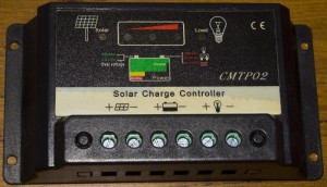
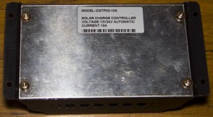
Posted in Teardowns on May 14th, 2015
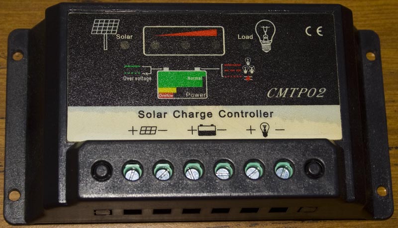
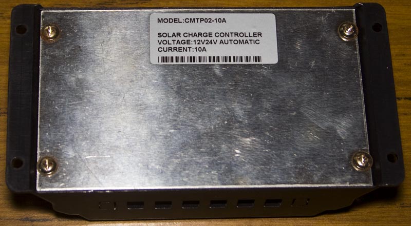
Today we’ll be taking a quick look at the Solar Charge Controller CMTP02 which is rated for 10A and used to recharge your 12V or 24V battery and power your load; they say that your solar panels / batteries should be matched, this was given to me and I believe it’s damaged.
A few seconds later and we’re in.
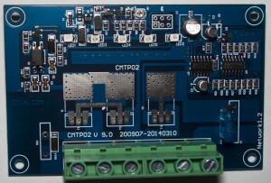
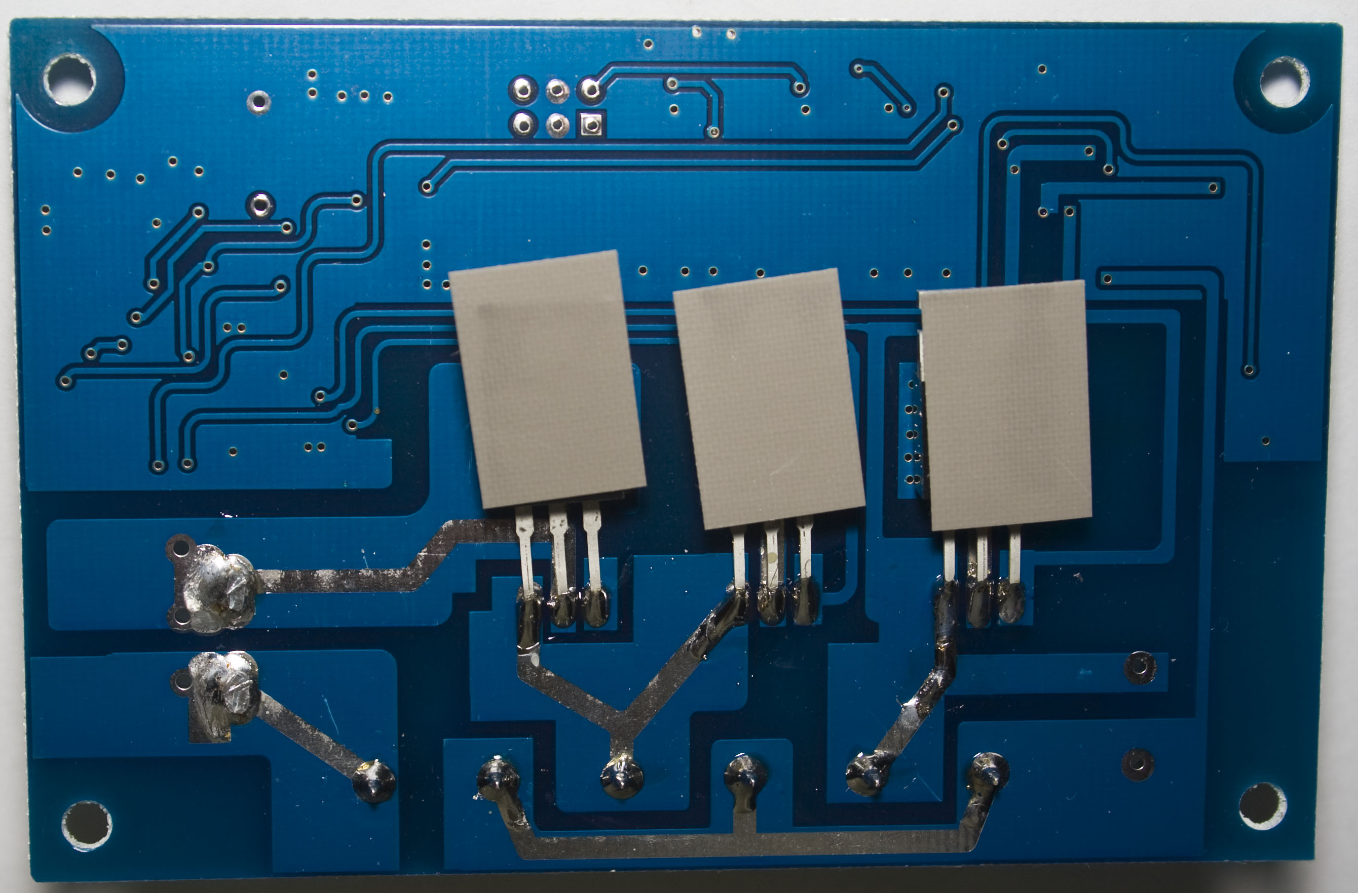
We’ve got all analog components, a fuse and 3 transistors or mosfets with no part number labeling and the back plate acts as a heatsink for them. The first 2 are connected together and configured to recharge the battery and the last one is used to switch the load. This solar charger (might) use PWM to charge the battery which means the solar panels voltage would directly be applied to the battery for a certain amount of time, it would probably be more efficient than using a DC-DC or transistor to step it down but not the best if something does go wrong. PCB date code is July 2009 to March 2014.

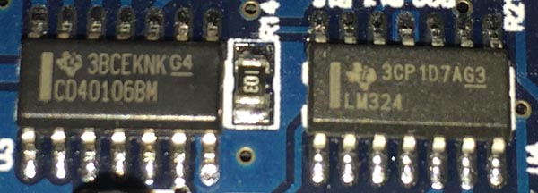
There’s a Ti CD40106B Hex Schmitt Trigger which is likely being used as an oscillator for the PWM and Ti LM324 op-amp with lots of resistors around it which would be used to control the transistors/mosfets and LEDs. Apart from that there isn’t much else.
Read Full Post »
Posted in Teardowns on Apr 21st, 2015
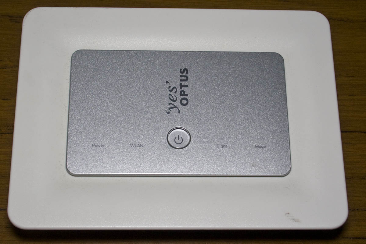
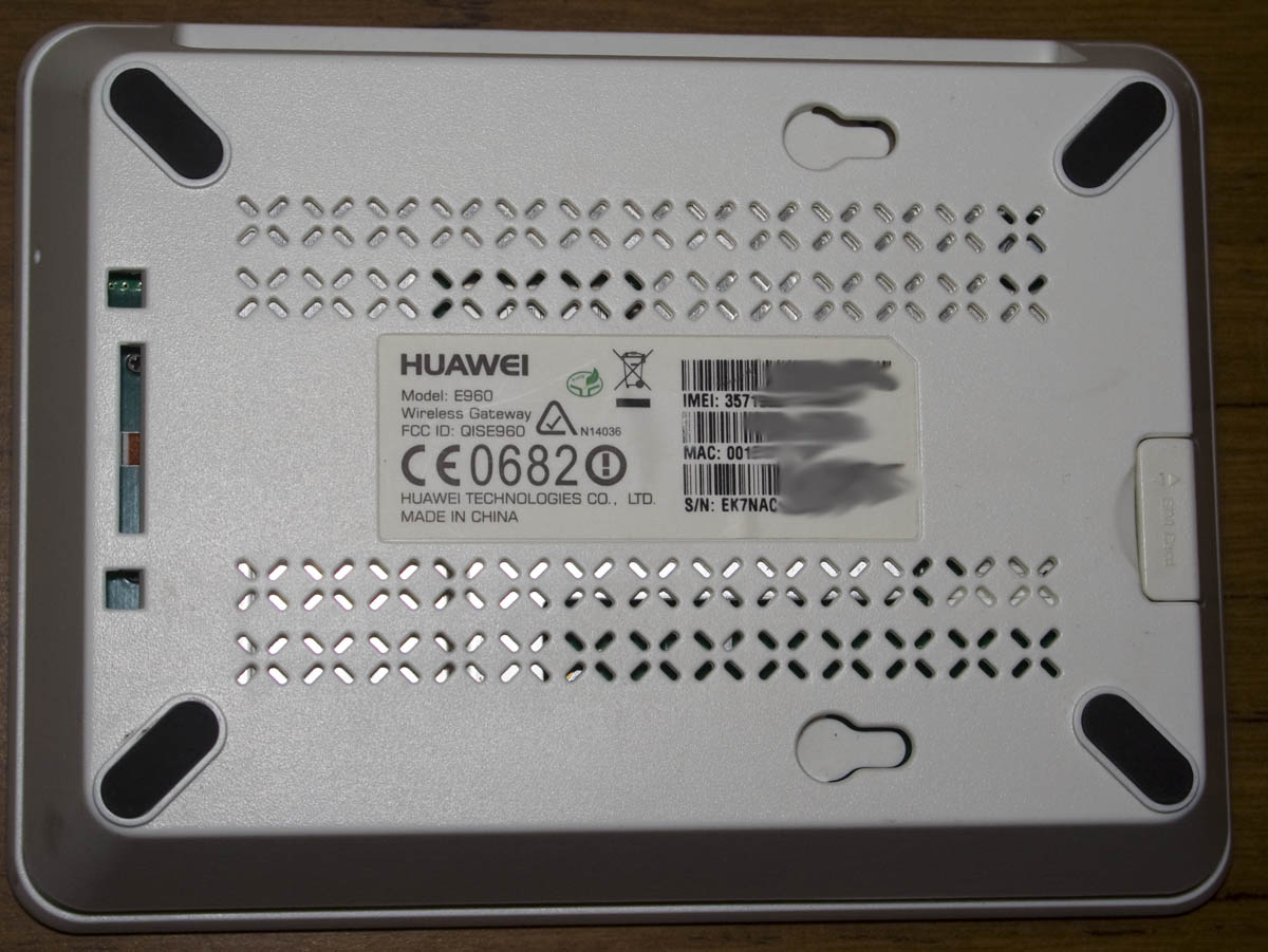
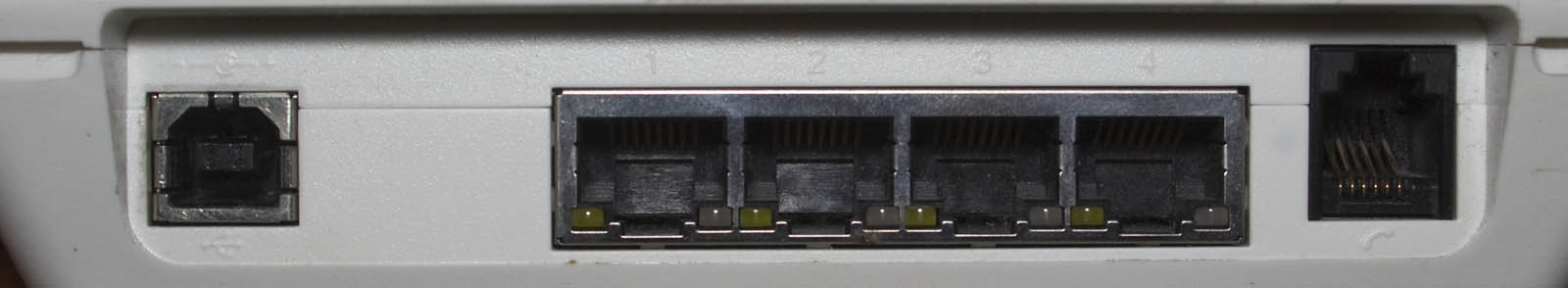
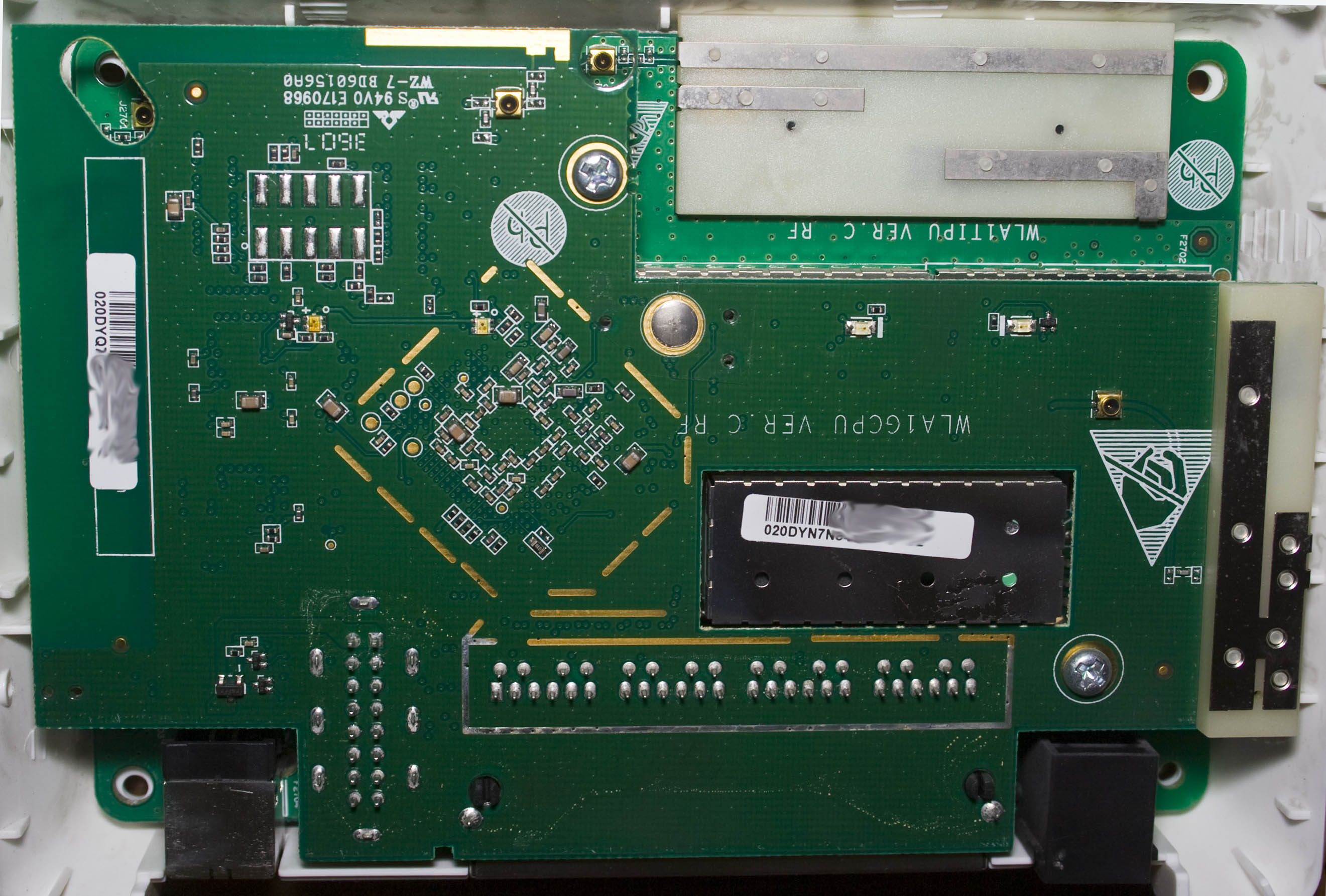
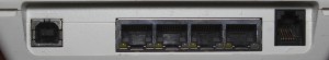
Today we’ll be taking a look at the Optus Huawei E960 3G Wireless Gateway (user guide) which is a 3G 802.11b/g hot spot with 4x 10/100 network ports, RJ45 port for connecting your phone and a USB port for power / ability to act as a modem on your PC.
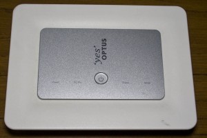
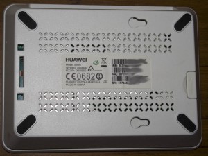
4 screws later and we’re in, the top just pops right off without any effort.


We’ve got a 2 board construction with a 16 pin interconnect and lots of shielding for each major component. There’s 3 antennas mounted on a plastic base which are screwed in place, I guess the reasoning could be that they are easily replaceable to suit the frequency band that’s needed. PCB date code is 36th week of 2007.
(more…)
Read Full Post »
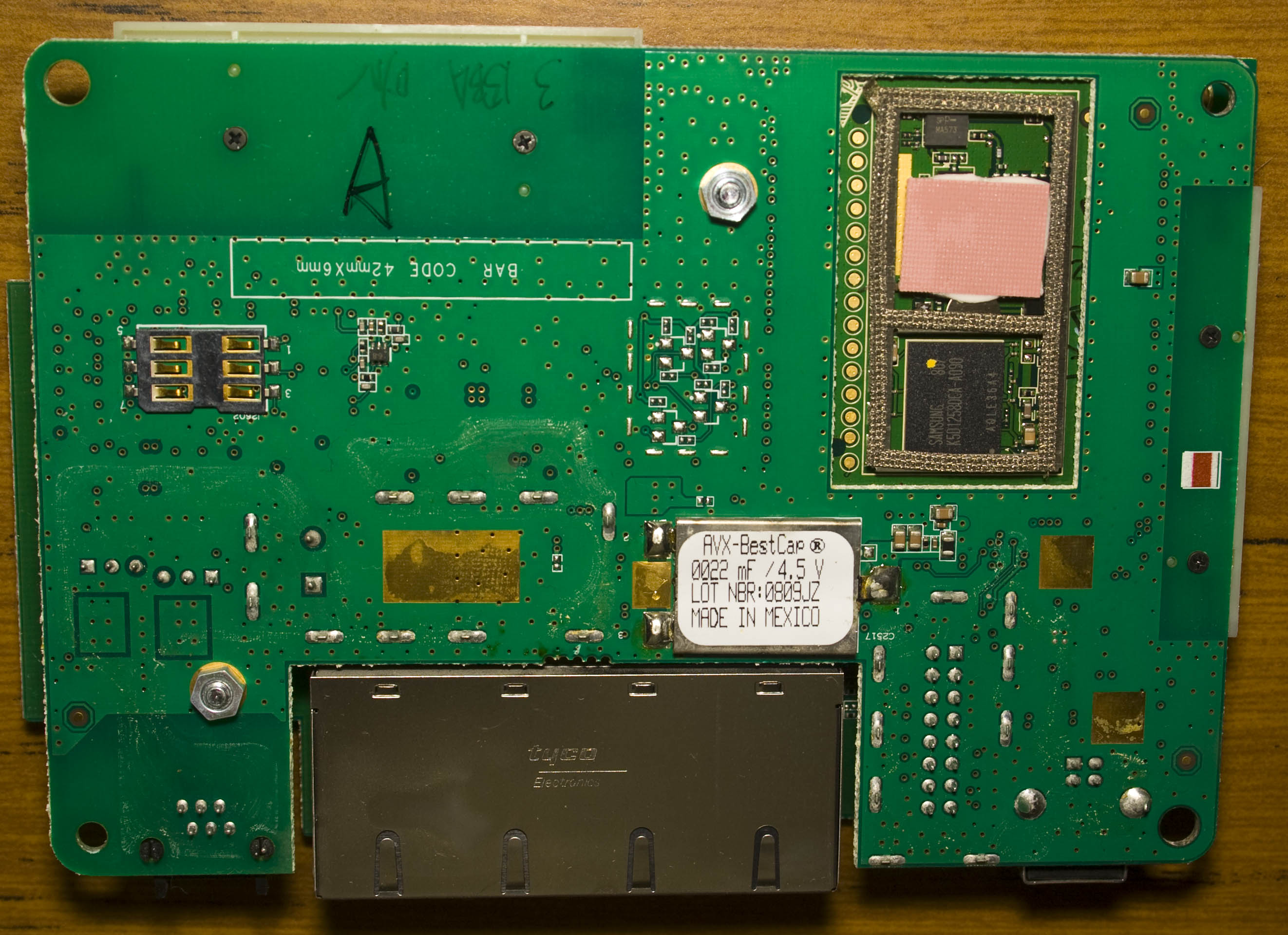
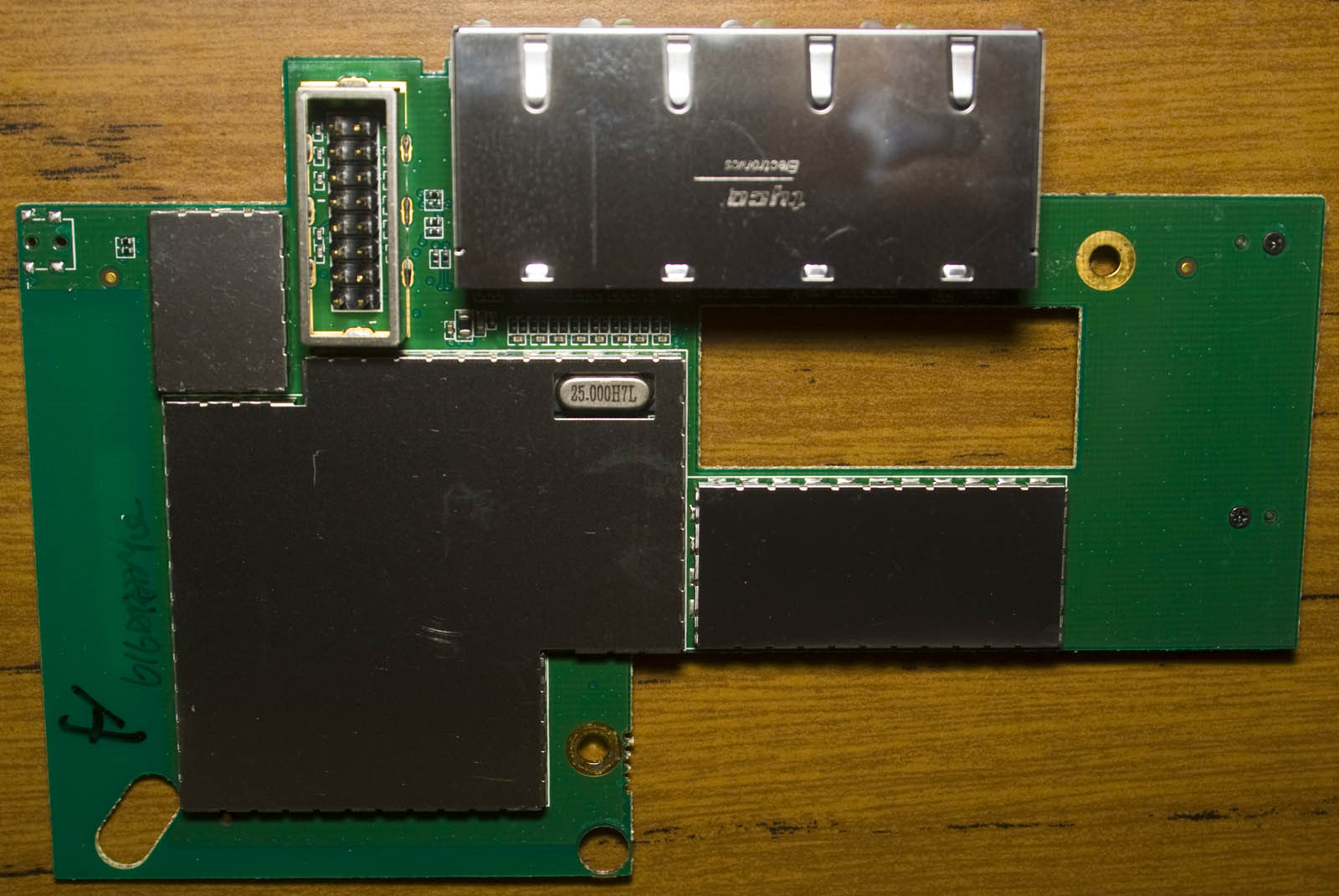
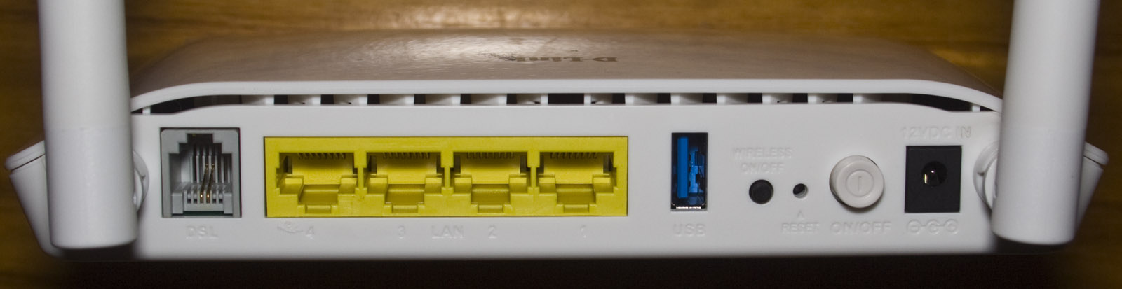
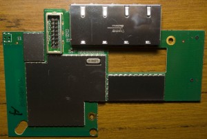
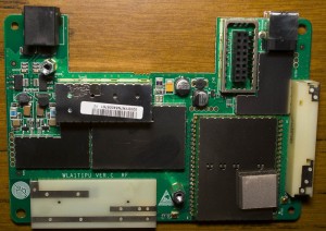
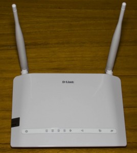
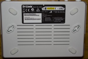
Posted in Teardowns on Mar 24th, 2015
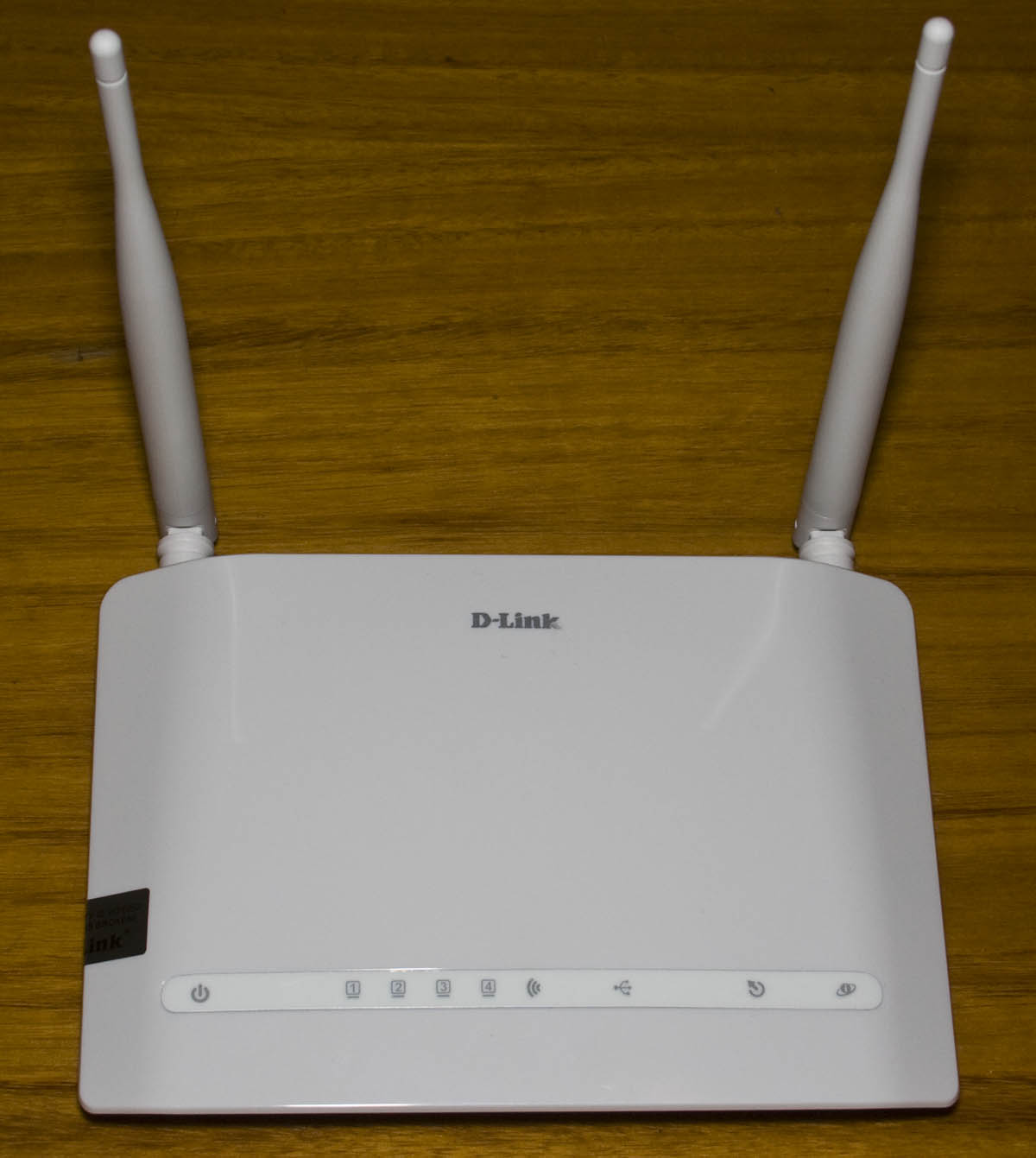
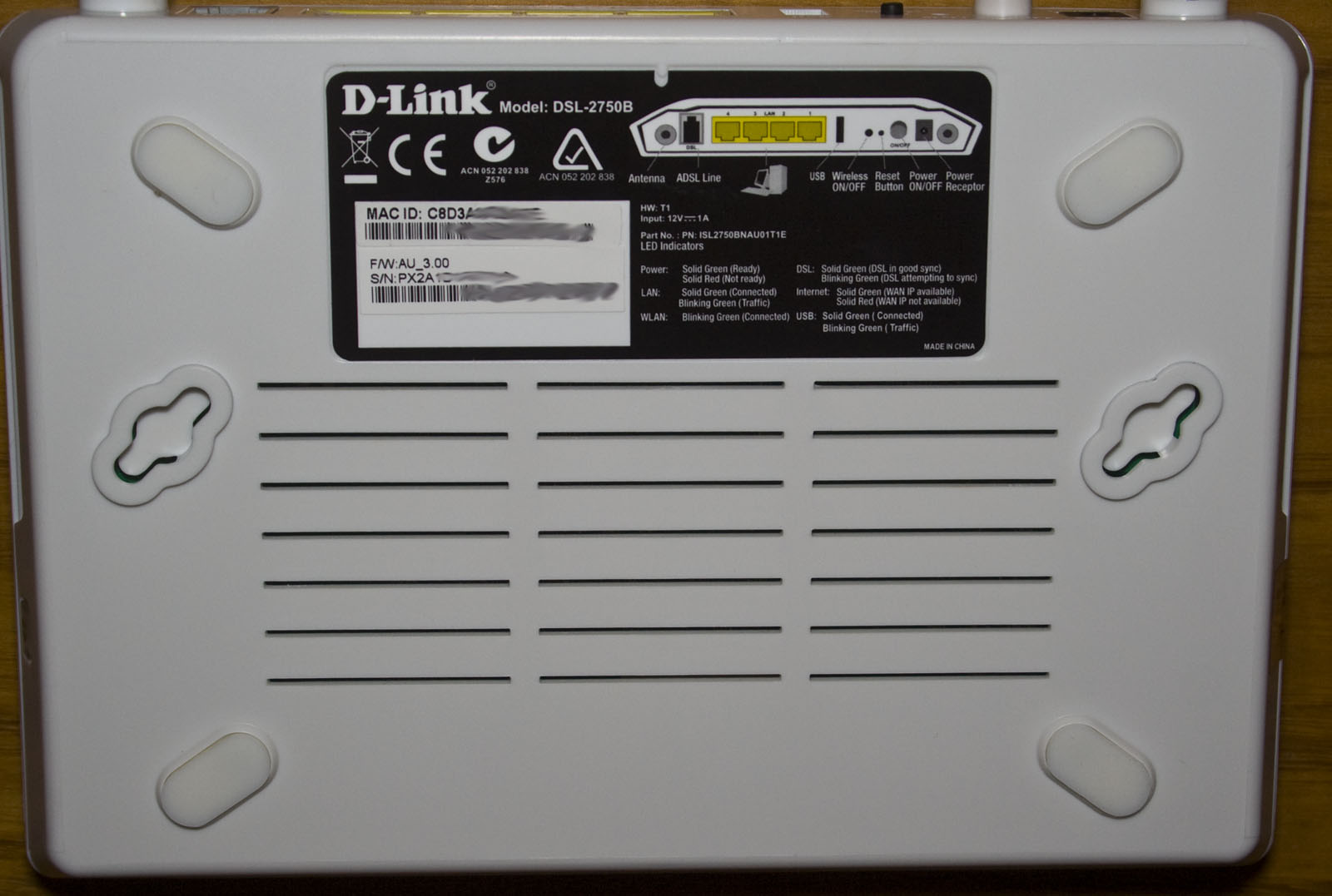
Today we’ll be taking a look at the D-Link Wireless N300 ADSL2+ Modem Router (DSL-2750B), an ADSL2+ wireless N router with 4x 10/100 network ports, a USB port for device/printer sharing and dual antennas.

4 screws later and we’re in.
We’ve got quite a few 25V 1000uF caps but they are CapXon branded ones and 2x Lelon 10V 470uF caps too. The antennas are soldered directly to the PCB and glued down, one of them has an RF choke and they’ve skipped the shielded can on the Wifi chip.

There is a header near an inductor which could be a serial header and instead of placing a thermal pad or paste on the main chip they’ve just placed glue and the heatsink on top, eh I guess they wanted to save cost.
(more…)
Read Full Post »
Posted in Teardowns on Feb 20th, 2015
Today we’ll be taking a look at the Feeltech 12MHz DDS Function Generator (FY2100S), it’s function generator that can do square, sine and triangle waves with sweep plus it’s a 1Hz to 60MHz frequency counter. It seems to work reasonably ok however there is a bit of jitter. Once you go over 8-9MHz – square waves don’t look like they should and the sine / triangle waves look similar too.
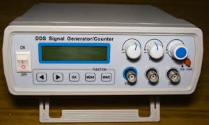
Once I picked up the case, it was very light so there’s probably not a lot going on inside.
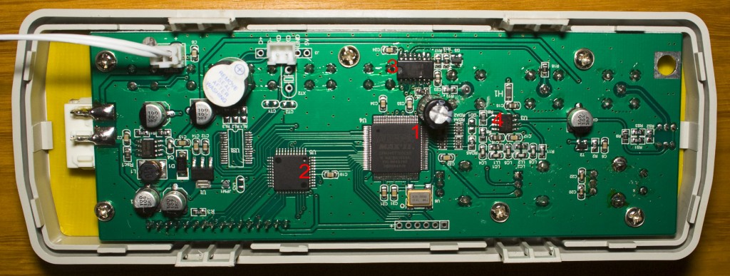
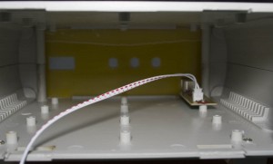
A few notches later and we’re in, this thing is pretty much empty with all the components being on the front panel – I might just remove the case and make a small back panel for it. We’ve got 5V input from USB, an MC34063 to invert the voltage to -6V (which gives us 12Vpp) and an AMS1117 3.3V LDO.
(more…)
Read Full Post »
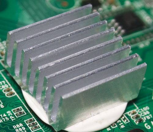
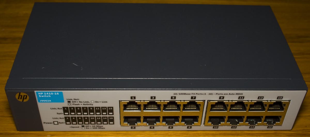
Posted in Teardowns on Jan 31st, 2015
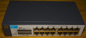
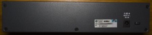
Today we’ll be taking a look at the HP 1410 16 Port 10/100 Switch (J9662A), it’s a 100Mbit 16 port switch so it’s nothing special but it’s suited more for the business environment due to it’s metallic casing.
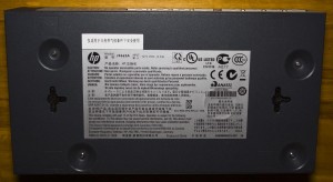
5 screws later and we’re in.
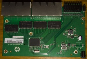
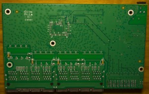
The layout looks neat and there is a lot of via stitching, date code is 7th week of 2013. We’ve only got 1 electrolytic capacitor on the board (at the input) and they skipped the need for inductors at the input. We have 2x MP1482 SMPS with 1uH unshielded inductors and they are relatively large considering that the input is rated for 12V @ 300mA, so the maximum current that could be used say ~95% efficiency at 5V is ~700mA. Also there’s 4x FPE H40520MN transformer modules and 14 transistors driving the 8×4 front panel LEDs.
(more…)
Read Full Post »
Posted in Teardowns on Jan 2nd, 2015
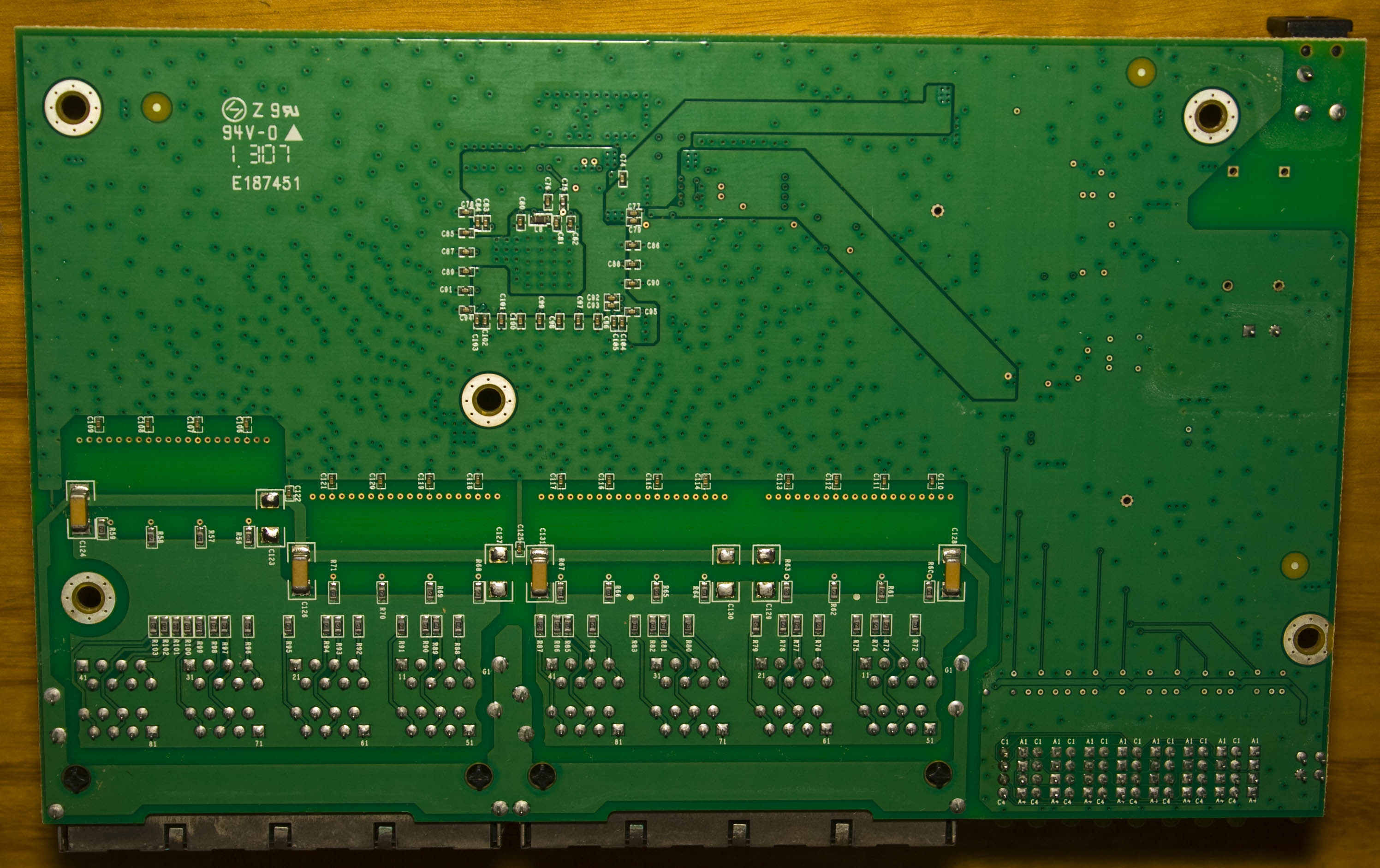
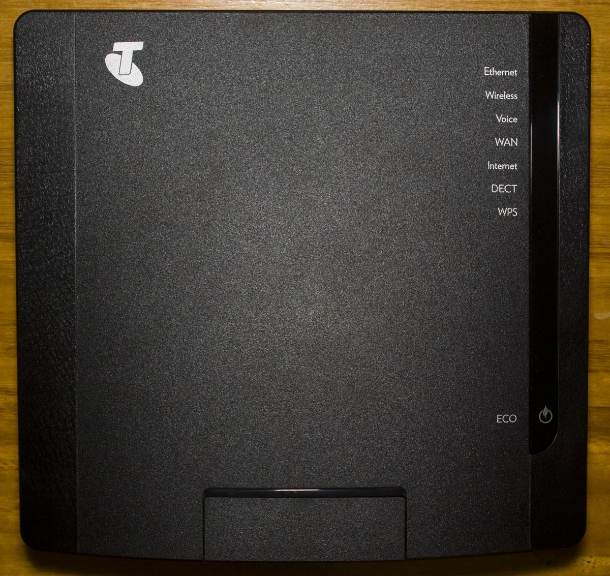
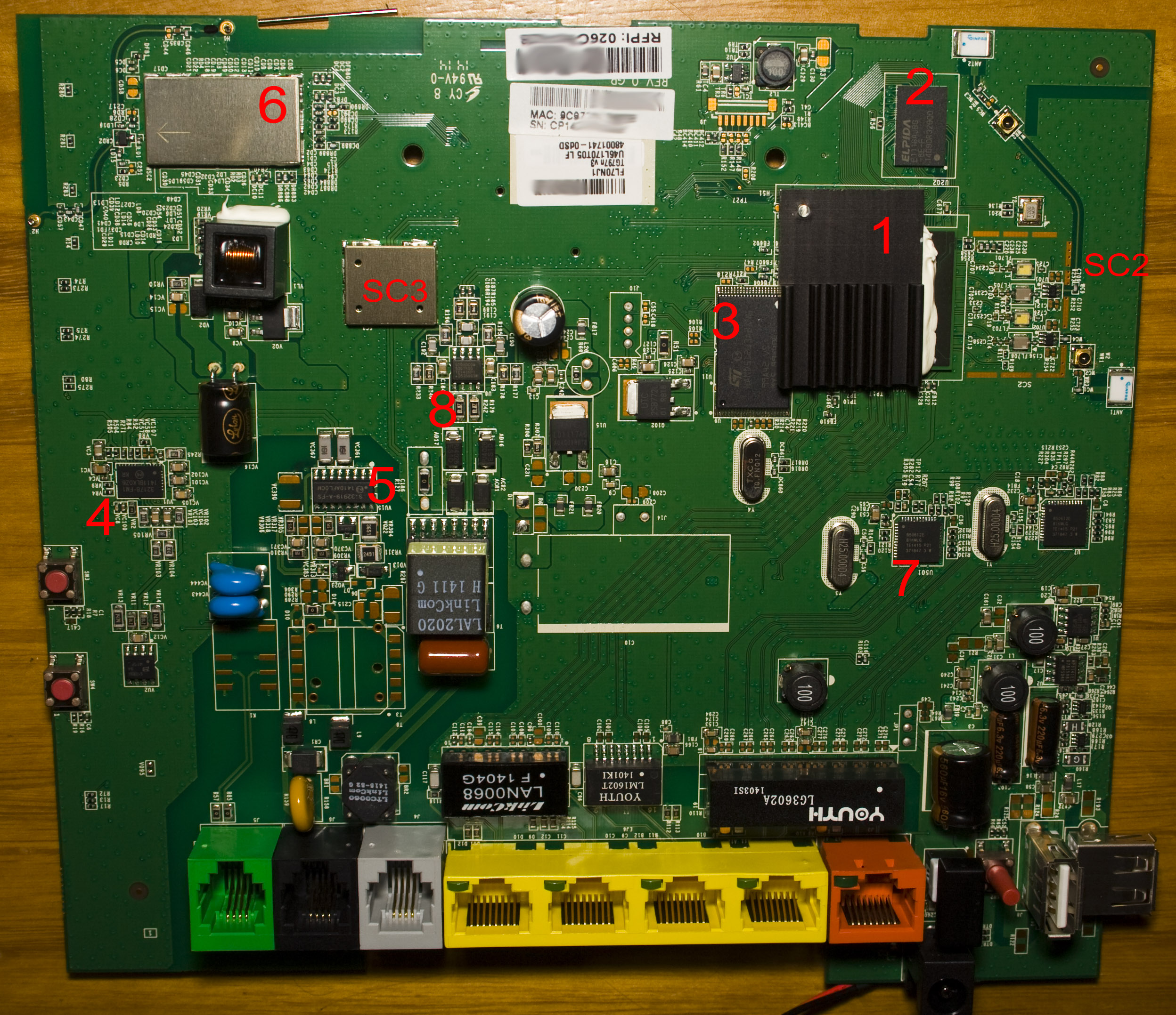
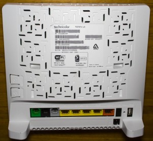
Today we’ll be taking a look at the Technicolor TG797n v3 Router (Telstra branded), an ADSL2+ Wireless router with 1 gigabit WAN and LAN port, 3 10/100 ports, VOIP, DECT and 2 USB ports. Once again this is another router which I haven’t heard of this brand before. It looks to be similar to the Thomson Gateway TG797.
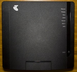

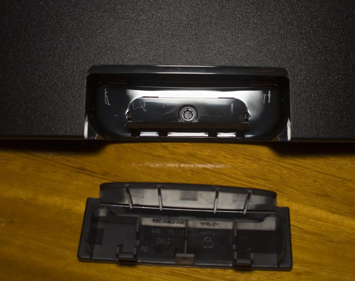
2 screws later and we’re in. There’s a small removable panel at the front which looks to be for a DECT cradle.


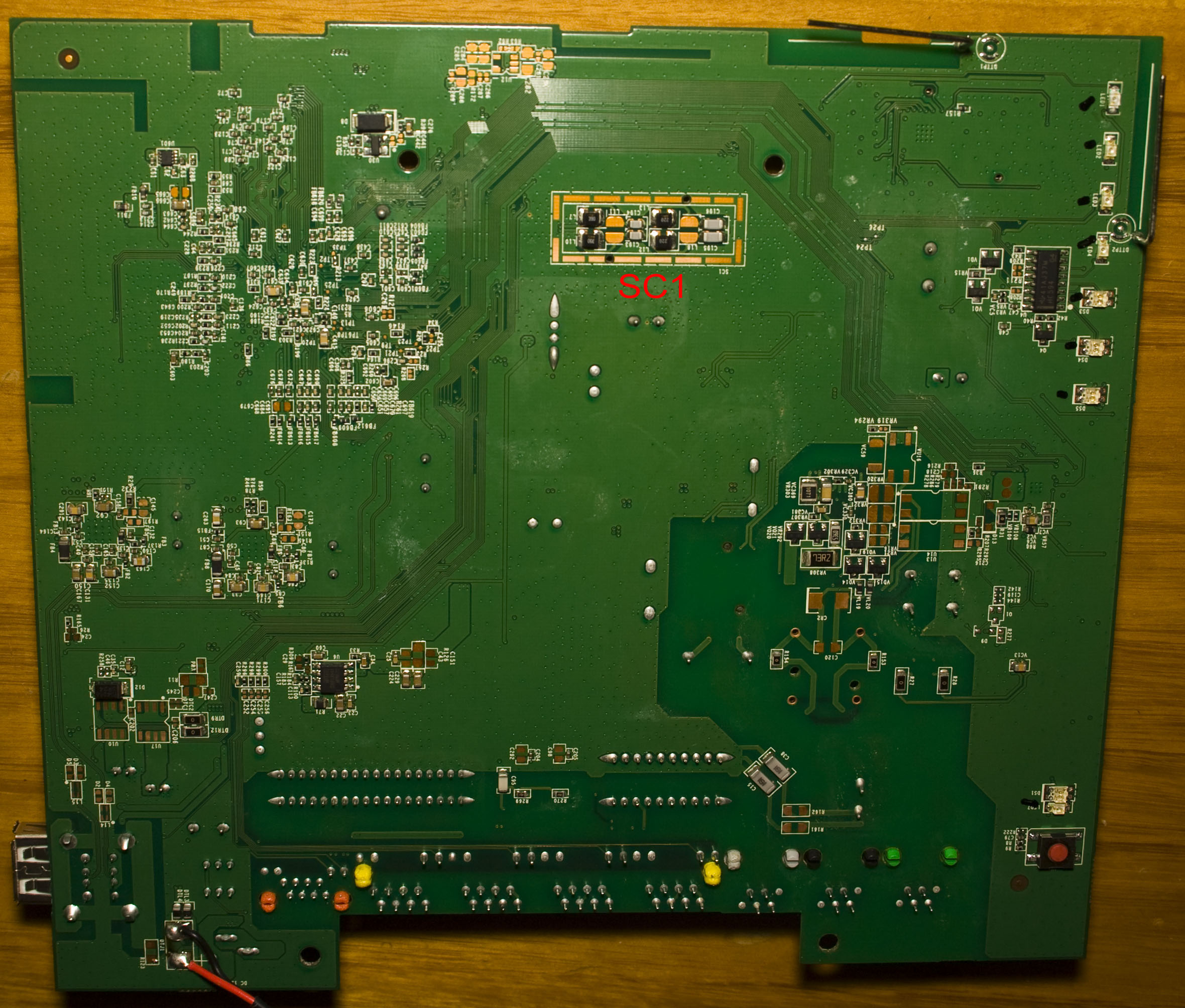
We’ve got a MP9141ES and 2x MP1492 SMPS near the input jack, an UTC LD1117 LDO and we’ve got Lelon branded electrolytic capacitors, there is a outline in the middle of the PCB for a very large capacitor. The PCB date code is 14th week of 2014 so it’s pretty recent. The heatsink that’s on top of the main chip has been soldered down using what looks like a nail on the top left and some epoxy to hold it down, the heatsink has a foot print which could have been a bit bigger. There are two metal cans, one for the DECT radio and one for something else labelled SC – which there are two more labels on the PCB, I can only assume it means “Special Circuit” or similar.
Looks like we’re missing the transformer from the PSTN black port but it’s still active and the green port is inactive according to the manual. There are 3 different transformers for the Ethernet ports, 1 that covers 2 gigabit ports, 1 for 1 LAN port and another one for 2 LAN ports.
(more…)
Read Full Post »