I’ve playing around with DC-DC step down converters but haven’t really had a need for step-up converters until recently. I have a portable device which requires ~12V 100mA so I’ve been powering it with 4x 3.3V LiFePO4 14500 batteries so it would be nice to reduce the weight a little bit by using a step-up converter knowing that the run-time will decrease.
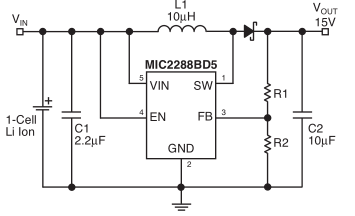
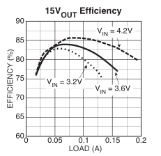
So I went looking around for some chips and found the Micrel MIC2288 for 90c which supports 2.5V to 10V input, up to 34V output and 1A switch current. A quick look at the datasheet and the BOM looks good and the efficiency chart seems to say it can do at least 100mA at 3.2V so it’s looking good.
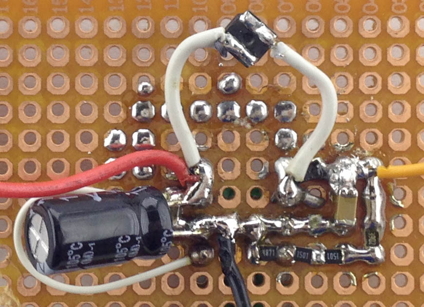
So I built it all up, used a 15uH inductor instead of the 10uH they showed. On the output I got 11.8V so all seemed well, put a 1.5K resistor (8mA load) which was fine, then I tried 330 ohm (36mA load) and that’s when I saw the voltage drop to 9V or so on the multimeter, strange plus I heard some sounds coming from the circuit. I started bumping up the voltage from 3.3V and once I hit 5.2V the output seemed to go back to 11.8V. I went back the other way, once I hit 2.3V to 2.8V it started working normally again. No components were getting hot.
I swapped the inductor for a 22uH one, same issue. I was about to measure the voltage across the Schottky diode when I touched the first lead to the SW (point where the inductor and Schottky diode meet) and the sound went away and the voltage went back to 11.8V. The current draw at 3.3V input was 150mA and it stayed the same when touching the SW pin. I swapped out the Schottky diode for a larger one but there was no change and touching the SW pin didn’t work this time.
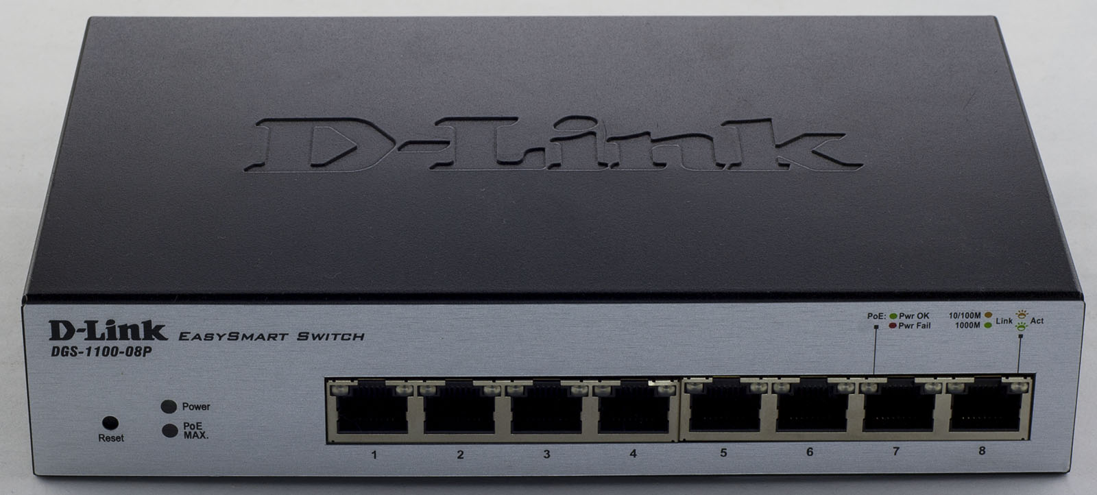
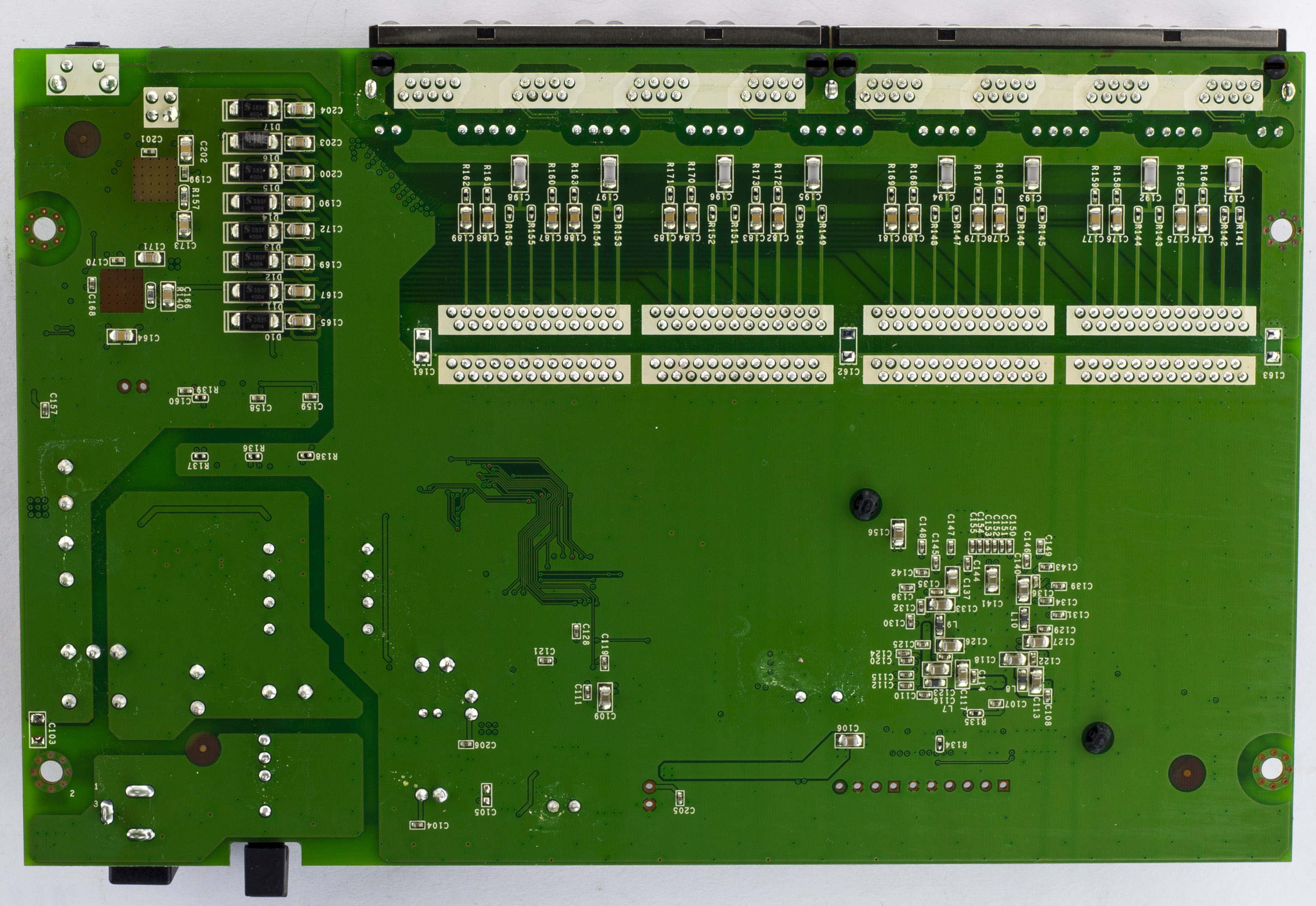
Today we’ll be taking a look at D-Link 8 Port Gigabit EasySmart PoE Switch (DGS-1100-08P) which is an 8 port switch with 8x 10/100/1000 ports with POE rated for up to 64 watts.
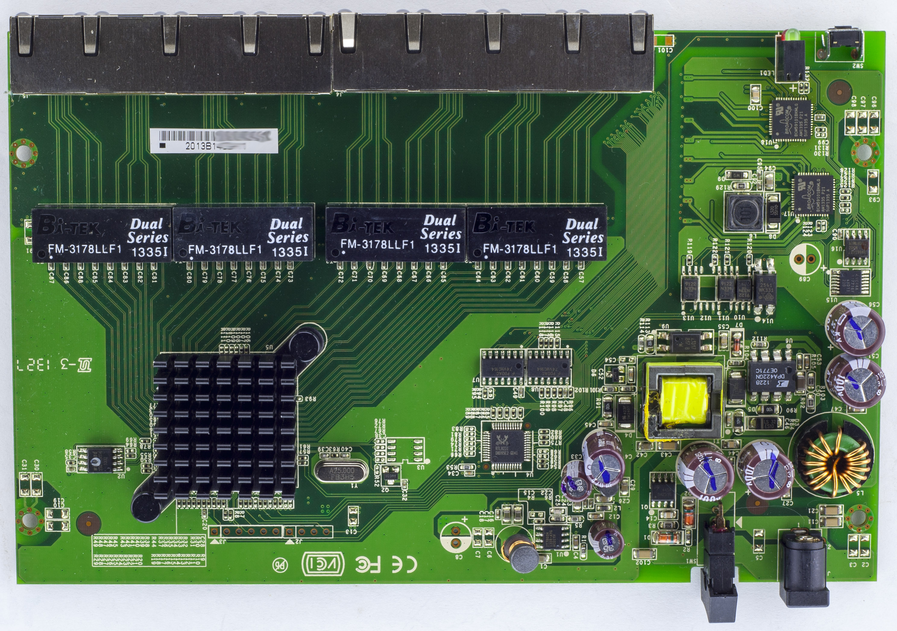
2 screws later and we’re in.
We’ve got our main chip with a decent heatsink plus 3 other chips. The PCB looks to have some isolation with transformers, optoisolaters between the 48V input / PoE side to everything else. We have a few logic chips – LVC14A Inverter and 2x 74VHC164 Shift registers. There are 2 headers, one 4-pin one 6-pin near the main chip. On the bottom of the board, we can see they left off the solder mask for slightly better power dissipation on the PoE chips. PCB date code is 27th week of 2013.
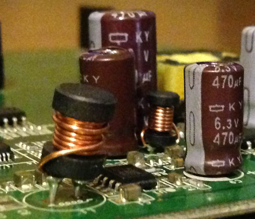
All the electrolytic caps seem to be branded KY. No SMD inductors were used which makes the smaller through hole inductors look a bit strange in how they were placed.
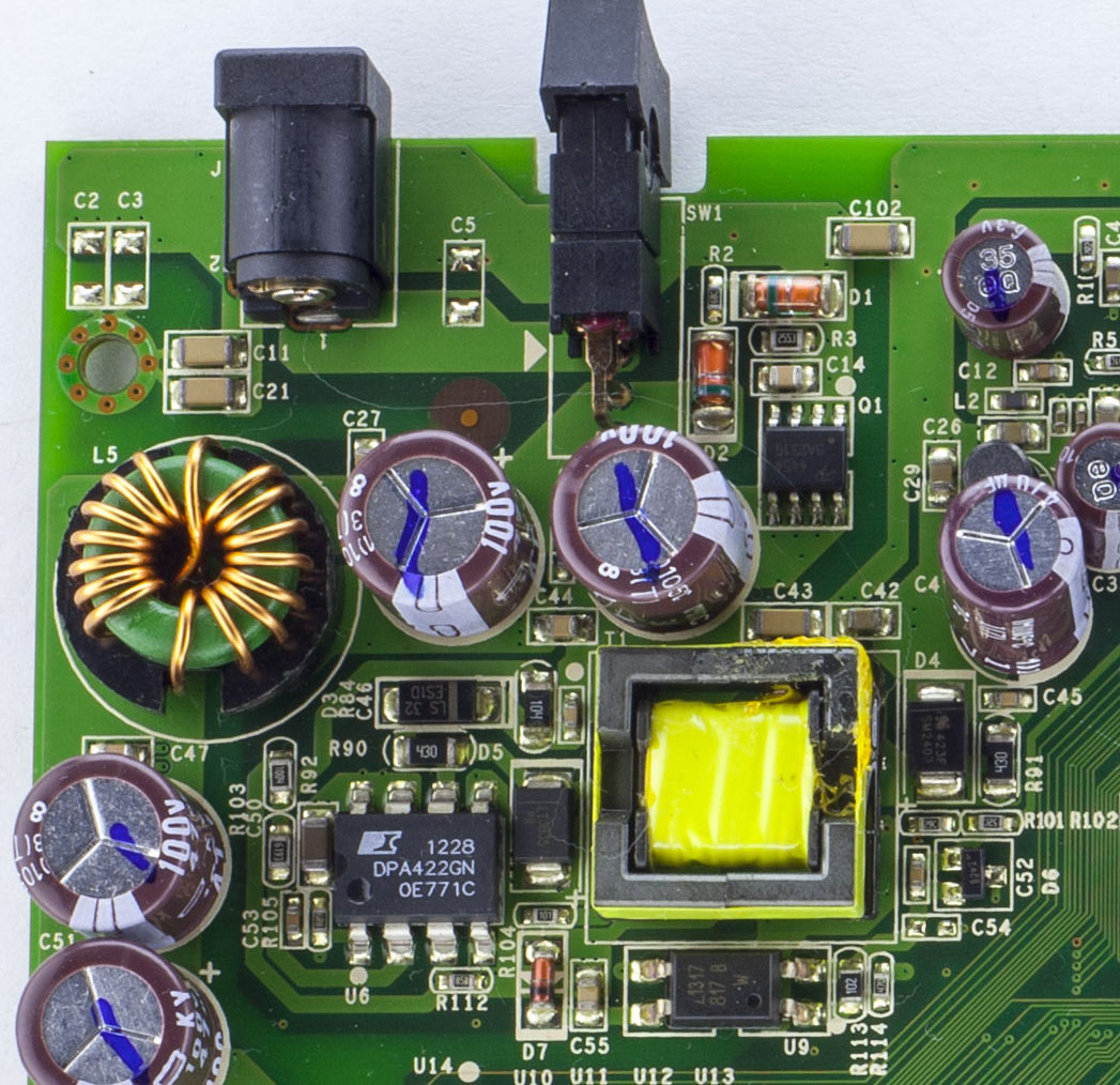
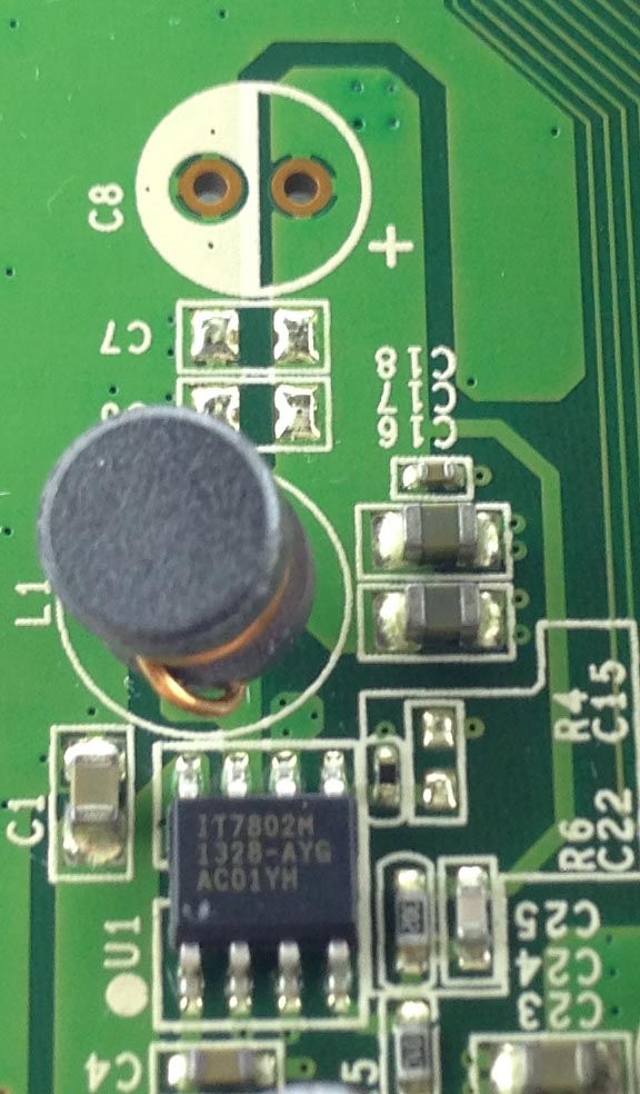
We have the 48V coming in, pass a switch rated for 3A then to the DPA422 DC-DC which provides an output through the transformer to lower the voltage for the M3Tek IT7802 DC-DC which outputs 5V. The 48V input also feeds directly through an choke to the PoE chips.
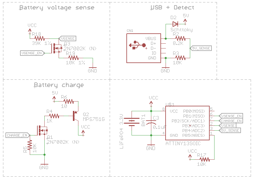
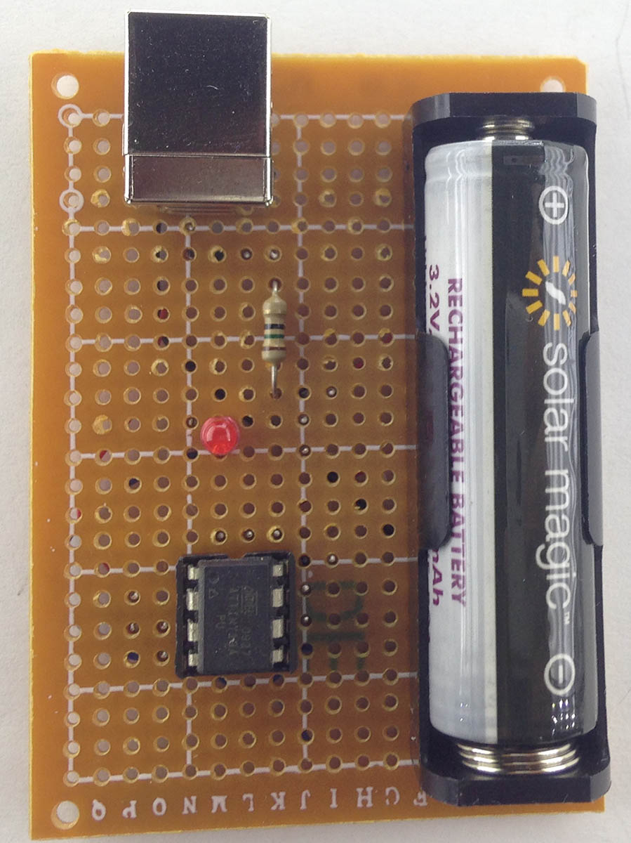
Since I’m starting to use more LiFePO4 14500 batteries I thought it would be a good idea to build a simple USB charger for them instead of having to charge 2 at a time on the xxx battery charger. The most simplest way would be to stick it on a CV/CC power supply or another way is to stick it on a CV power supply set to 3.6V with say a 1 ohm resistor and wait for it to reach 3.6V, not the quickest to charge but it works.
My first design was to use a voltage reference such as a TL1431M (or a resistor & zener diode) set to 3.3V with a decent op-amp like the MCP6242 with hysteresis threshold set to 3.2V – 3.6V and an PNP transistor to switch the 5V through say a 10-20 ohm resistor to the battery. This would only charge the battery if it was under 3.2V, stop at 3.6V and won’t start charging again until the battery dropped back to 3.2V which it shouldn’t.
It works one problem arises when you unplug the USB side and leave the battery in, it would start discharging a few mA due to being connected to the op-amps output but it’s not like that would really ever happen. But let’s put in an MCU, say an ATtiny13A to sort it out. I have plans to make a device in the future run off the LiFePO4 battery and recharge itself when the USB cable is connected if it matches the threshold voltages as before.
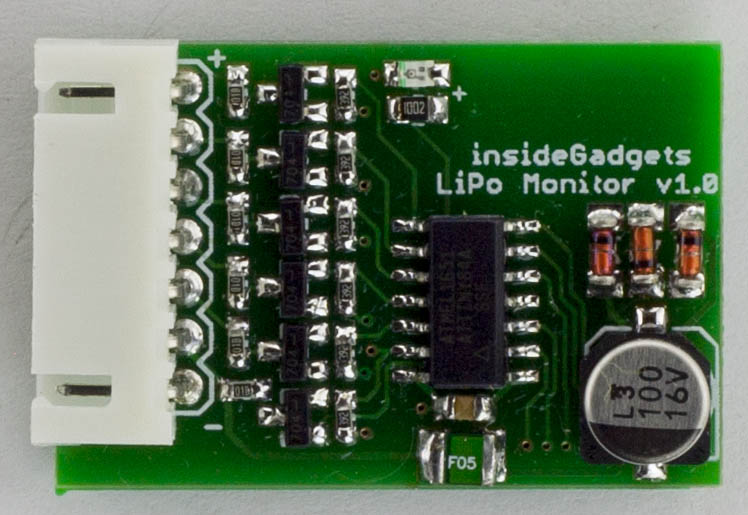
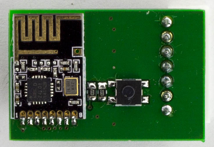
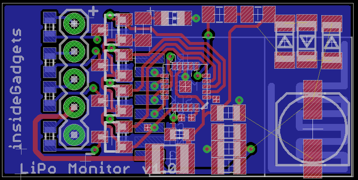
From our previous part, we designed a client with the nRF24 which communicates the LiPo battery cell voltages to a server running from an ESP8266 so we could easily jump onto it and check the cell voltages. In this part we’ll add in email alerts with adjustable battery voltage thresholds, add an easy server setup process to join your Wifi and give the system a test.
First things first, the client PCBs arrived (34 x 23mm), built one up and it worked well. I sprayed the board with PCB lacquer and put clear heat shrink over it. When trying to link it up to the server, it wasn’t working, seemed to just stay waiting to receive the packet from the server. I eventually found out that I had to bump the voltage up to at least 3.9V for it to link up properly, I’m guessing the 3 diodes dropping the voltage down is part of the issue when listening as it can take quite a bit of current. Sending a packet when it checks in works fine at lower voltages. When ATtiny and nRF24 are sleeping, it takes about 6uA so I’m happy with that.
I was thinking about redesigning the board to make it even smaller (32 x 16mm) if you just had up to a 4 cell battery, it would be a little bit harder to build.
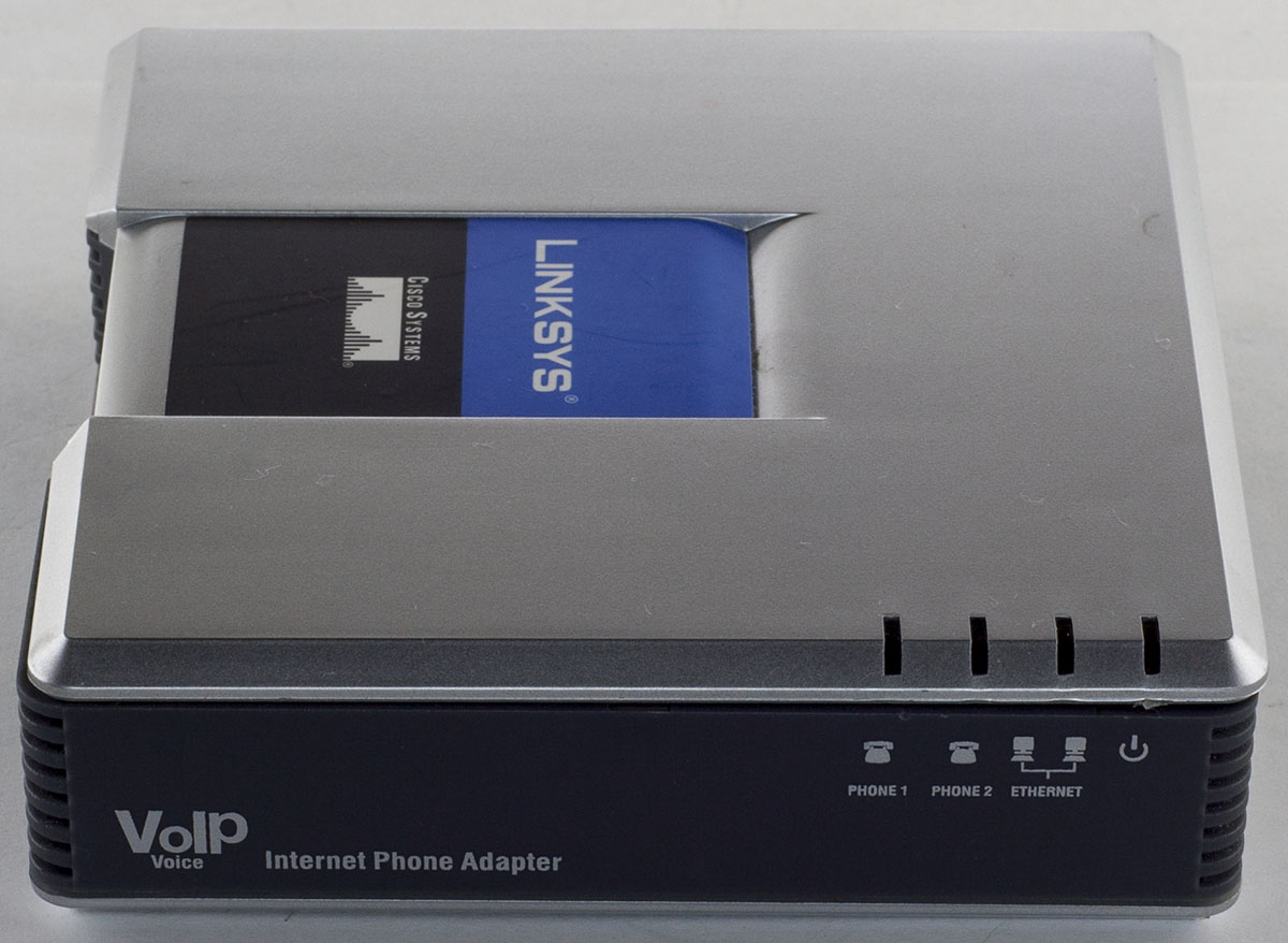
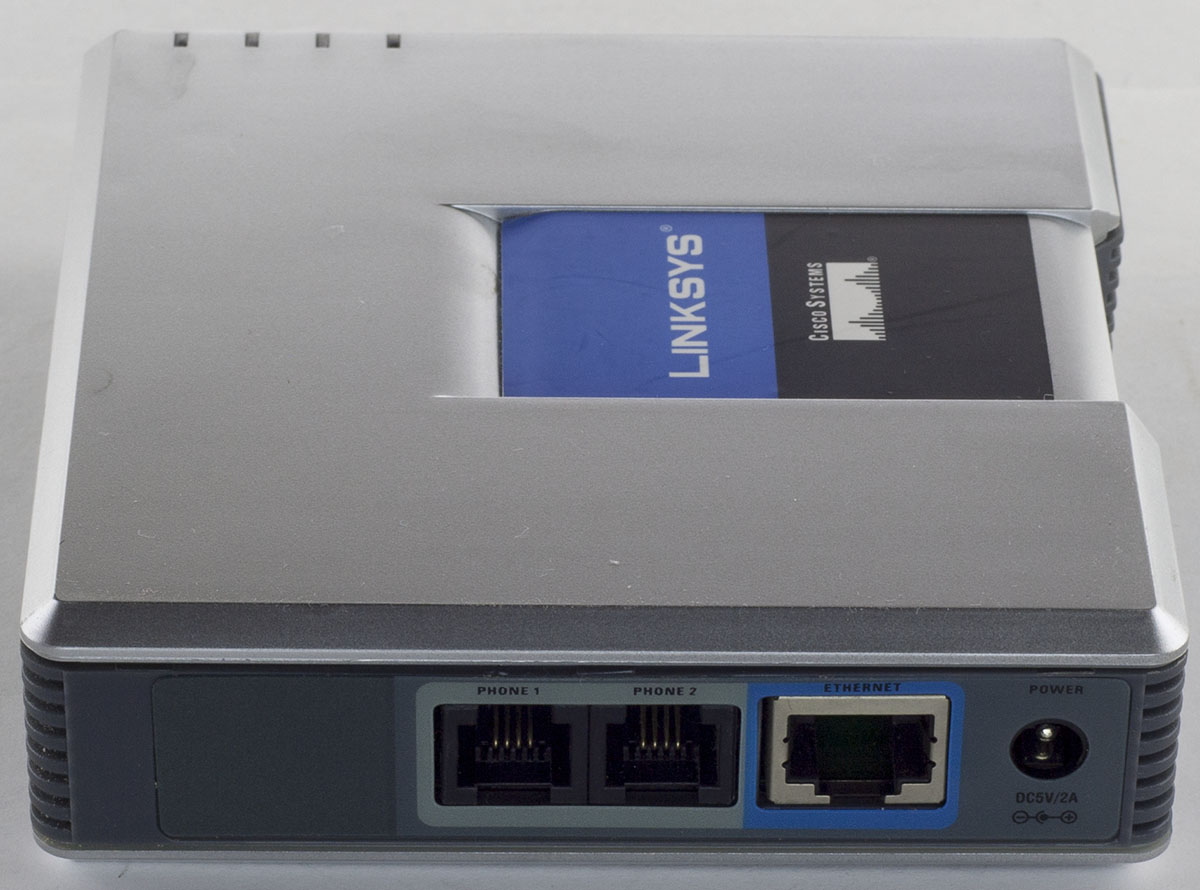
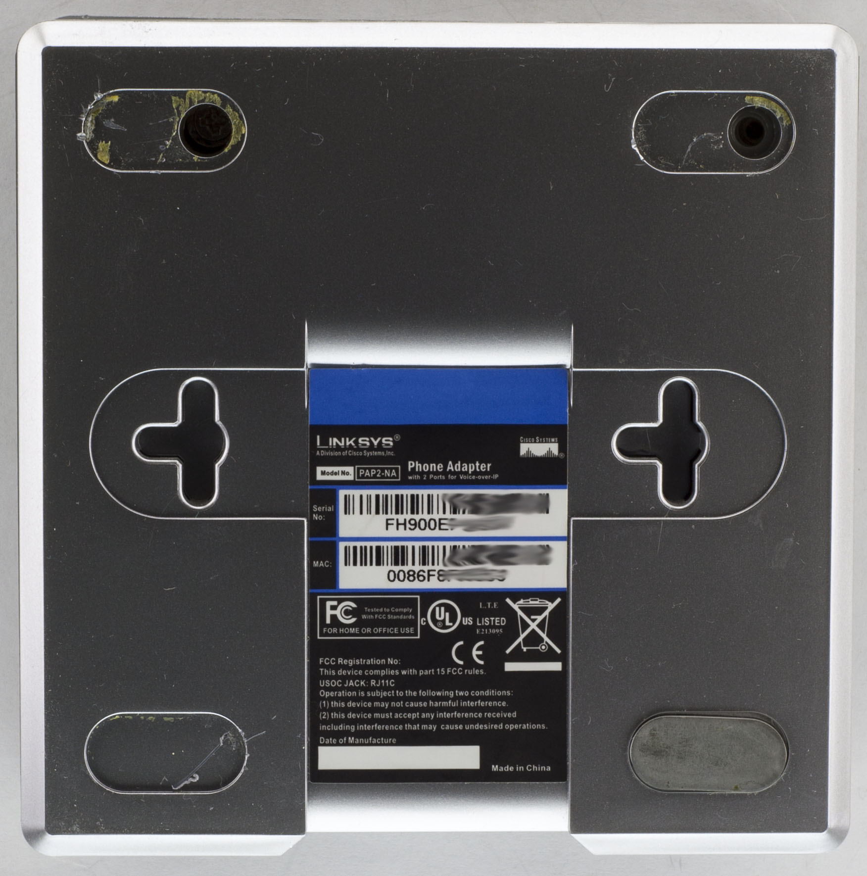
Today we’ll be taking a look at the Linksys PAP2 VoIP Phone Adapter which has an Ethernet port and 2 phone ports for analog phones, powered using a 5V adapter.
2 screw at the back, 1 screw on the side and we’re in.
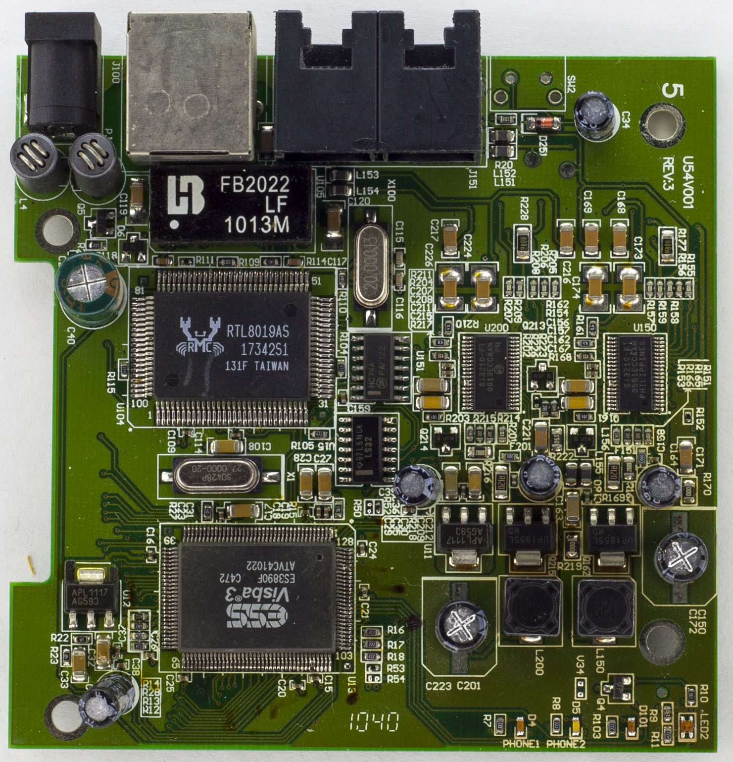
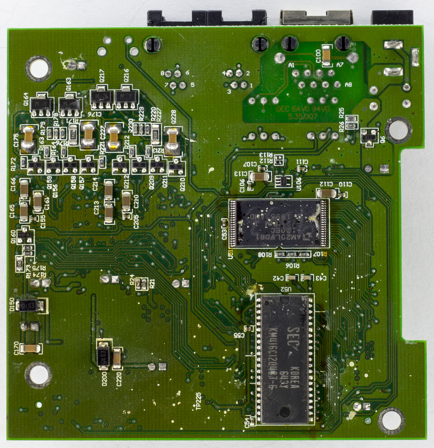
We have a 2 chip solution – the main chip and LAN controller. The bottom of the board looks like it’s seen better days and there are some spots around the board that looks like burn marks, not sure if someone else has opened this up before. For the power side, there are 2 chokes before going through a PNP transitor to a 470uF capacitor and we have 2 AP1117 LDOs giving out 2.5V and 3.3V. There are 2 logic chips around as well, an LS32 a quad OR gate and a HC74 Dual D Flip-Flop with S/R. PCB date code is 40th week of 2010.
From the previous part, we designed a small power supply based on a Richtek DC-DC, added an 128X64 OLED display and gave it a quick test which it seemed to cover most voltage ranges with better increments than the old SPPS.
(sneak peak)
The PCB’s arrived and we’re ready to start populating each segment individually to make sure each part works. I put on the ATmega328 with the LCD, tested ok. Next was the main DC-DC converter with digital potentiometer and to test controlling it from the ATmega which seemed to work fine. One thing I hadn’t really paid attention to was that the DC-DC converter only goes up to supply voltage – 2V or so from my testing, the reference voltage starts to drop from the nominal 0.8V and it started to oscillate, so I might need a 18V power supply if I want up to 15V output.
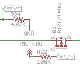
Output Enable troubles
Next I soldered the P mosfet for the enable so I could enable or disable the output, that’s where things didn’t go as planned. I hadn’t considered the case where the power supply was set 2V and the gate was low, Vgs would only be -2V which is not enough to turn on the mosfet, you need something like -5V or higher to full switch it on, basically under 5V it was unusable, the mosfet would be dropping most of the voltage.
My small bench is located in one corner of the living room next to a sliding door so soldering fumes didn’t appear to be much of an issue when I had a fan blowing the solder away from me.
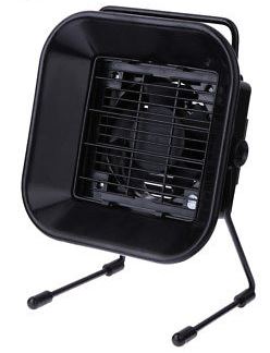
I thought it was probably time for a small upgrade so I bought one of the Solder Fume Extractor’s from Ebay, $24 locally, a bit pricey for what is it. Once I received it, it seemed to work fairly well, the distance you could be away from it and it still suck the fumes was around 15 to 20cm. If you didn’t want it that close, you could always use another fan to gently blow towards the fume extractor or use some materials to focus the suction of air.
After using it for 10 minutes, the fan started to smell and was getting a bit hot too. I left it running for an hour but still had the same issues, ugh, so it was time to take it apart and see what I can swap out.
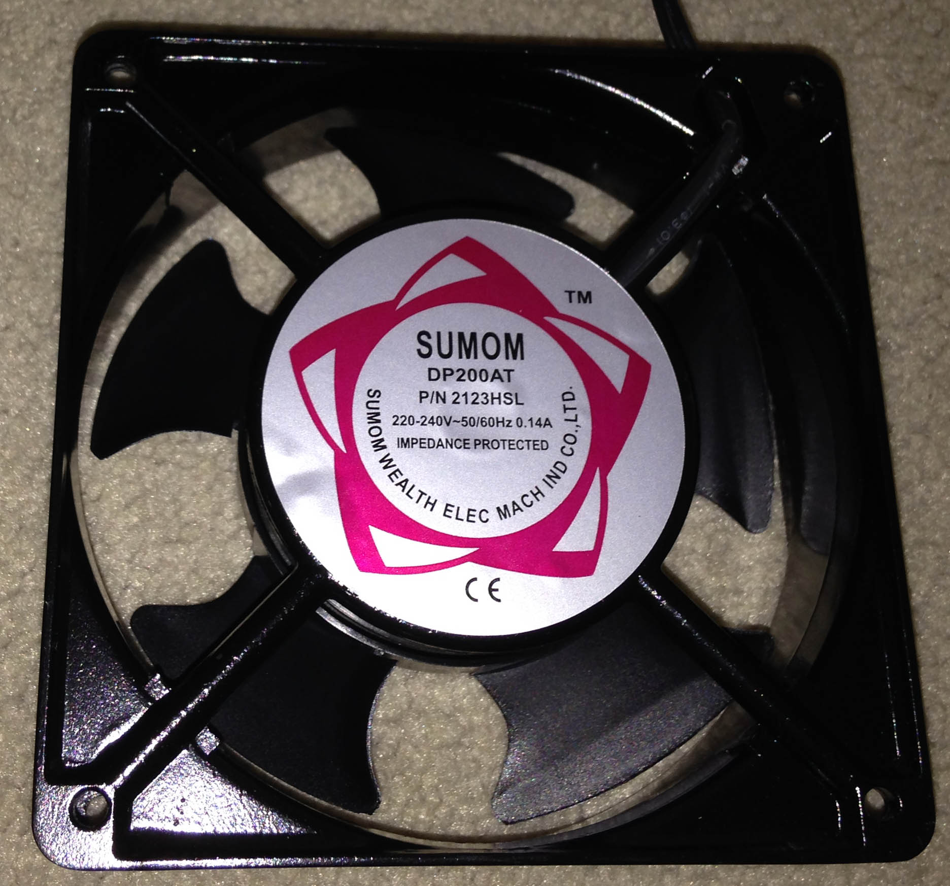
The device has the AC power cord going directly into it, so I thought they might have a AC to DC converter with a DC fan. That wasn’t the case, upon unscrewing the 4 screws at the front, it’s an AC fan. Power is just running though the switch to the fan.
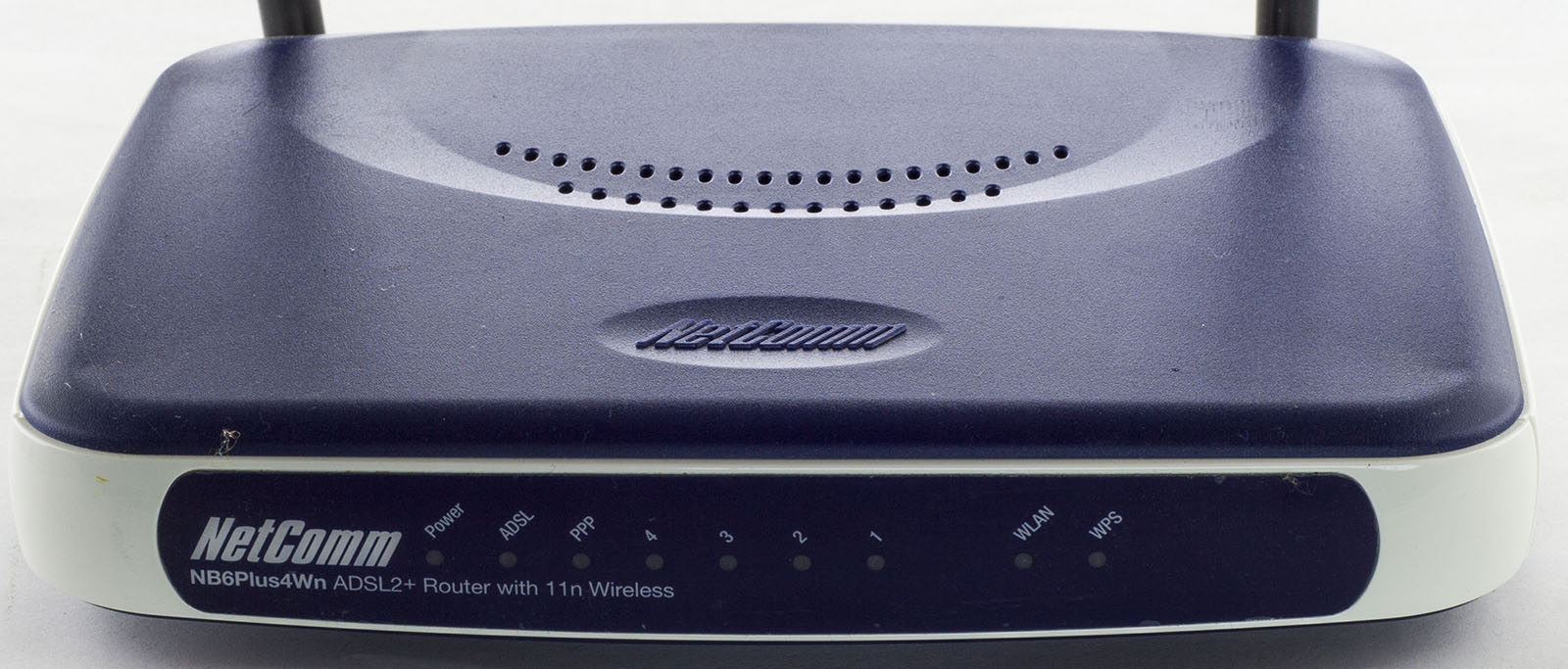
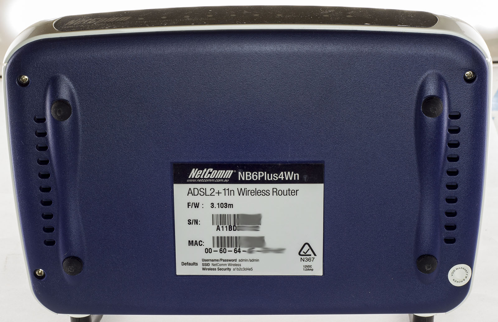
Today we’ll be taking a look at the Netcomm NB6Plus4Wn ADSL2+ Wifi Router which is similar to the Netcomm NB6 Rev2 ADSL2+ we looked at previously except that this one has 802.11n Wifi and 4 LAN ports.
4 screw later and we’re in.
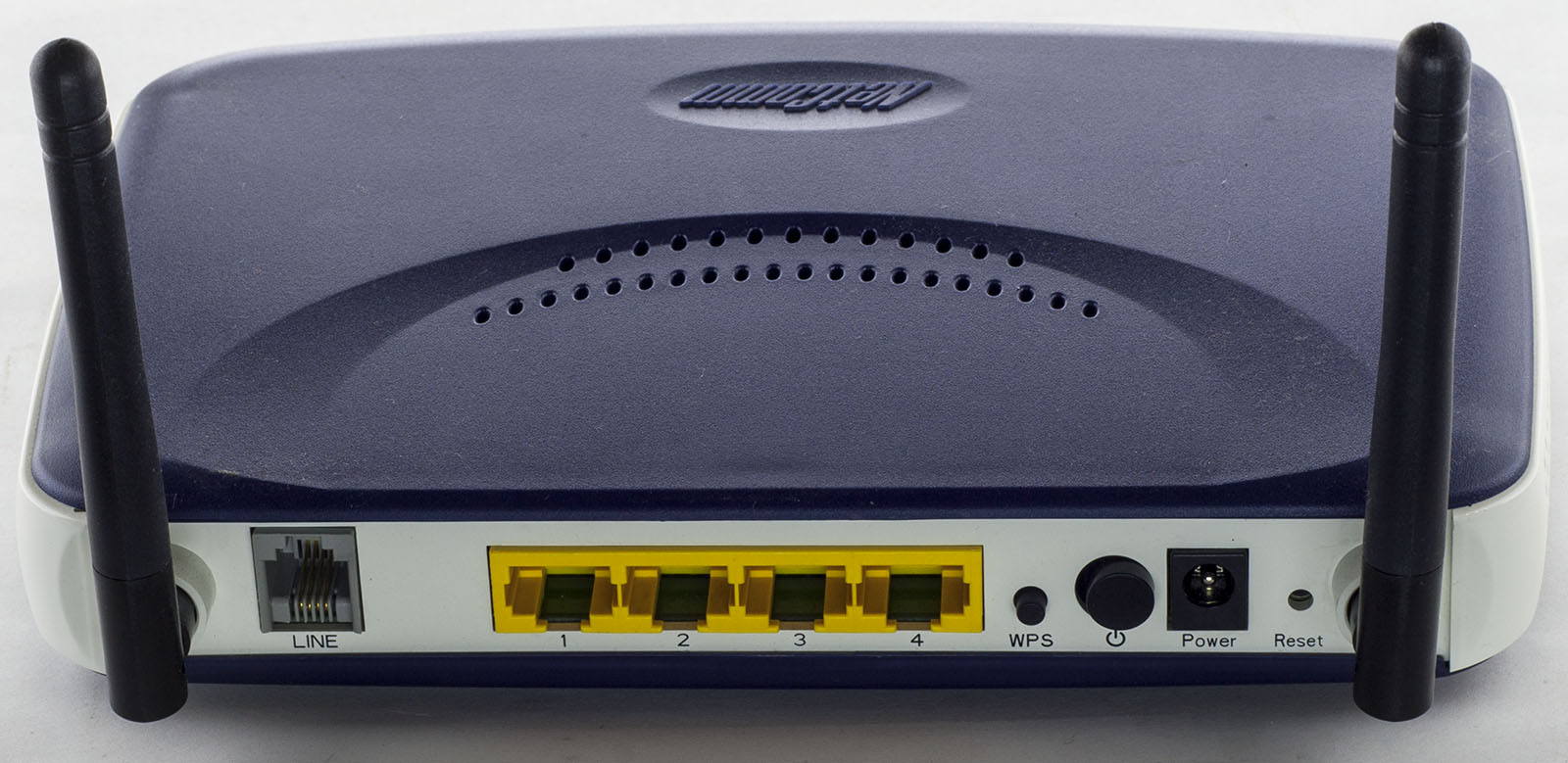
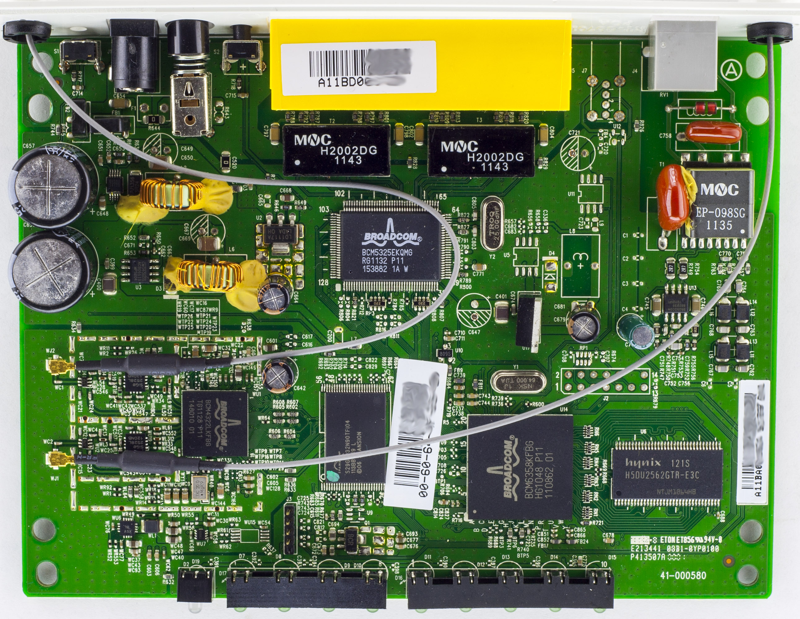
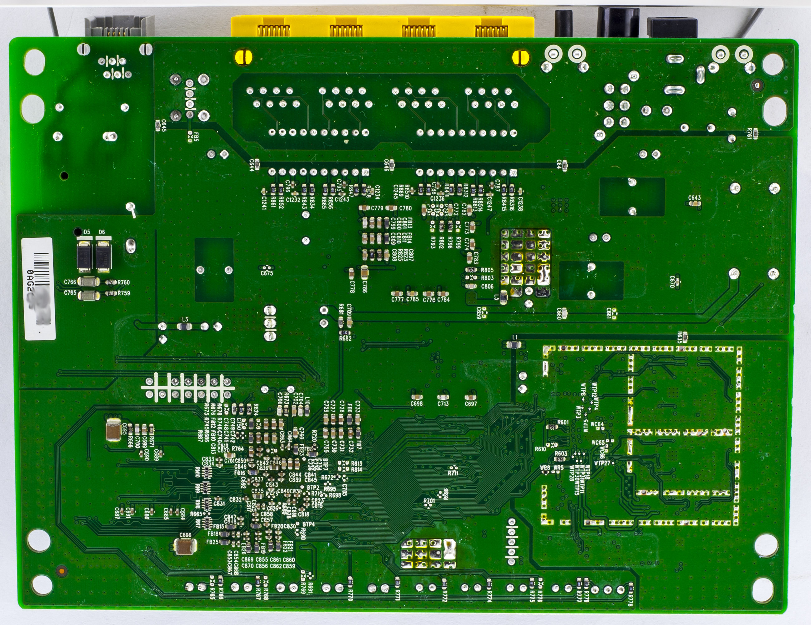
We’ve got a 3 chip solution, the main chip, LAN controller and Wifi controller which is using a discrete front ends for both antennas that look to have a balun in them. There’s a 5 pin header with only 4 pins soldered going to the main chip. Looks like there is also possibility for populating a USB header near the phone line port. PCB date code is 42nd week of 2011.
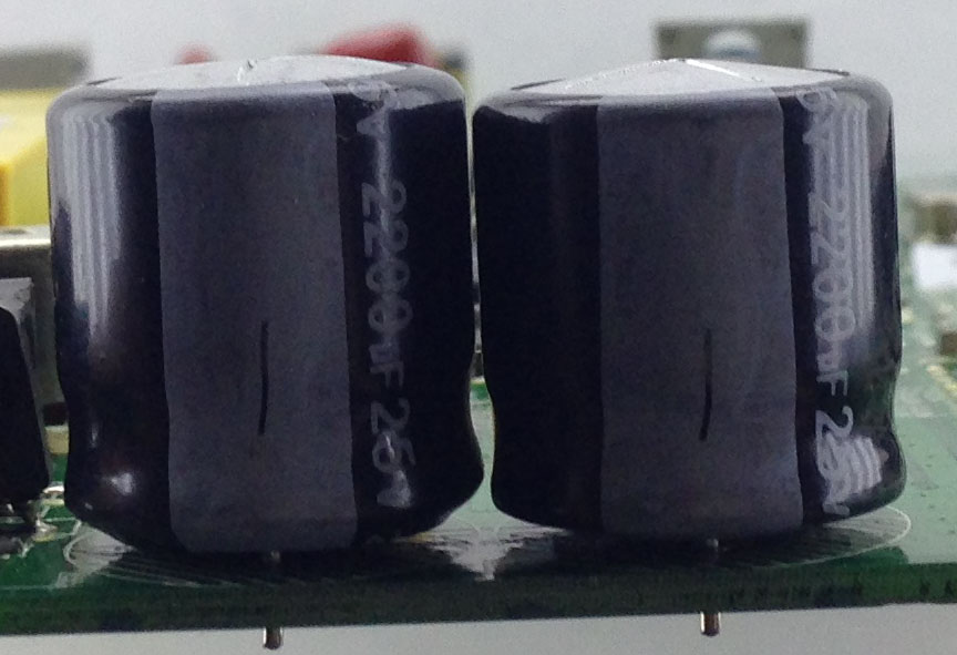
Something that stands out is the 2x Lelon 25V 2200uF caps which are swelling. We have a little bit of glue being used on the 2 inductors for the DC-DC’s as well as the one of the red caps to the line transformer.
Wouldn’t it be nice to know it you have mail? I think it’s a good idea and had it on my to do list for a while. Our letterbox looks similar to the one above, you can place small items on the top, in the letter slot or open it up from the back.
At first I thought we could do this with a vibration switch however upon testing the switch it looks like it needs a fast motion in order to activate. Another option is a reed switch on the top part so if the mailbox is opened, it will detect that, but would leave letters undetected. And yet another option, is a light sensor placed inside the mailbox but also results in the same problem.
So one of our last options is to use an accelerometer to detect the slightest touch of the mailbox, most mailboxes are pretty rigid but ours has a tiny bit of moment to it, we can’t really put the device we would make in the letterbox itself as the RF would mostly be blocked so it would have to be placed outside. As usual, I’ll be using an ATtiny84 with the nRF24 to simply send a packet when the interrupt occurs.
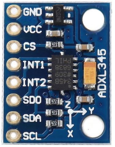
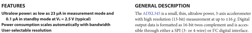
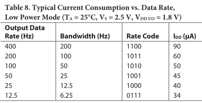
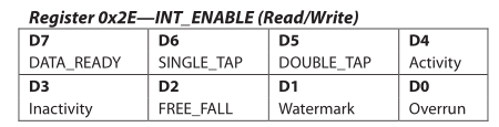
The accelerometer I’m looking at as you can tell by the title is the ADXL345 which has 2 interrupts available for single tap, double tap, activity, etc, and current consumption looks to be pretty low. It supports I2C or SPI, we’ll be using 4-wire SPI.
So I tried the SparkFun ADXL345 example which worked well, they have all the interrupts available so all I need to do is take everything I don’t need out, convert it to C and try out the low power modes. Note that the ADXL345 is a 3.3V device so you will need a logic level converter if using it with a 5V Arduino.
I have a couple of nRF24 devices around the house like the doorbell, front door camera, the single receiver for both and I might look to expand that list in the future but re-programming the receiver when you would like it to handle a new device or perform an additional action can take a while plus the time testing that everything works.
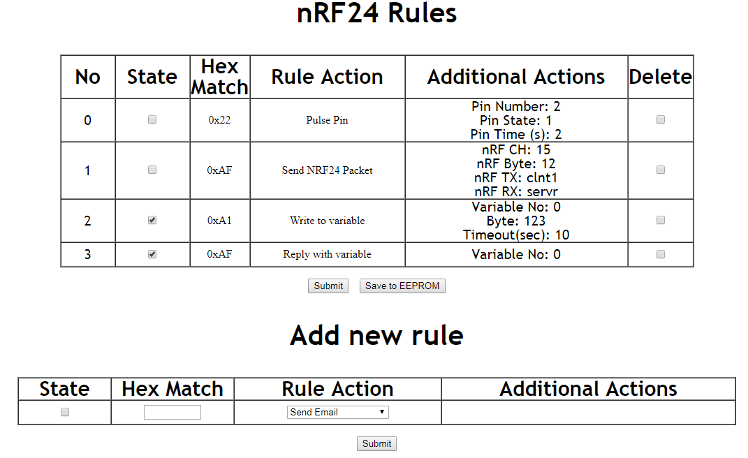
So I thought, why not make an ESP8266 for a web interface where we can store rules and have it connected to the nRF24 to receive incoming packets, it’s similar to IFTTT but all local. The rules would all be based on a single byte packet it would receive, we could have the rules active or not, with rule actions such as sending an email, pulsing a pin for a certain amount of time, sending an nRF packet, writing data to a common variable (with a timeout when it’s reset) and reply back with that variable. We can have a button to save everything to the EEPROM (emulated on flash) and read it all back if the ESP8266 is power cycled.
Some quick use cases:
– Doorbell is pressed, you could either have it pulse the buzzer locally for a second or two and you could also have a remote buzzer anywhere else so it sends a packet to have that buzzer go off too.
– I’m thinking about adding a small sensor to the mailbox, so if it’s moved, it would send a packet, we could have it write data to a variable. Add a battery powered sensor anywhere around the house with either a buzzer or LED, to check in every few seconds and read that variable back so if it changes to a 1, the buzzer or LED goes off for a little while.
AdvanceVGA – Play your GBA on the big screen! Swap out the LCD for our board, solder some wires, connect 5V USB and VGA and you’re ready to go.
GBxCart RW allows you to backup GB/GBC/GBA ROMs, save or restore game saves and re-write supported flash carts. Mini RW option available for GB/GBC only.
Wireless Gameboy Controller – Use your Gameboy, mGB, GBC, GBA, GBA SP, GB Micro, NDS and NDS Lite as a wireless controller on Windows, Linux, Raspberry Pi, etc, and on your NES, SNES, N64, Gamecube and Wii.