Automatic Voltage Switcher
Jul 4th, 2011 by Alex
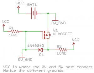
The Automatic Voltage Switcher utilises a diode, resistor and N channel Mosfet which allows automatic switching of the voltage sources if one of the sources is connected or disconnected.
Parts required
R1 – 10K resistor 1/8W
D1 – Diode (schottky diode recommended)
Q1 – N Channel MOSFET (Gate source needs to less than the lower of the two voltage sources, e.g if 3V and 5V, needs to be less than 3V Vgs)
VCC-Low – Low voltage source (e.g 3V)
VCC-High – High voltage source (e.g 5V)
Make sure the difference in voltage between the VCC-Low and VCC-High is more than the diode’s breakdown voltage. I would recommend at least 1V difference.
Schematic

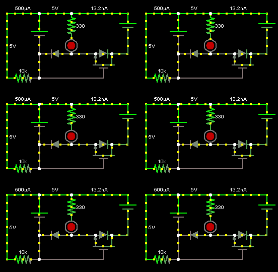
Example: 5V battery on the left, 3V battery on the right. 5V battery is connected.
How it works
Assume we have 2 voltage sources, 3V and 5V. When the 3V is connected, the 10K resistor connects to the N Mosfet gate which gives it 3V so it turns on and allows the current to flow from VCC through the load to 3V_GND. No current flows through the diode because it there is no connection from the diode to VCC.
Once the 5V source is connected the 10K resistor and diode are both on however since 5V_GND is ground, active this means that 0V is at the end of the 10K resistor and diode. This turns off the N Mosfet as it’s gate voltage is 0v and allows the 5V to run through the load. The 5V doesn’t reach the 3V battery because the N Mosfet’s internal diode blocks the current flow (it goes through the 3V battery but never reaches ground).


