A little while ago I picked up a low cost 3D printer, the Malyan M150 and after printing all sorts of things from Thingiverse, I decided to move over to designing cases for my projects which was the original intent for the purchase.
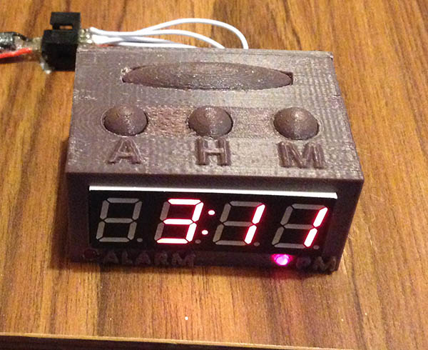
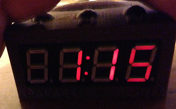
(old alarm clock – 16 x 11 x 5cm) (new alarm clock – 6 x 4 x 3cm)
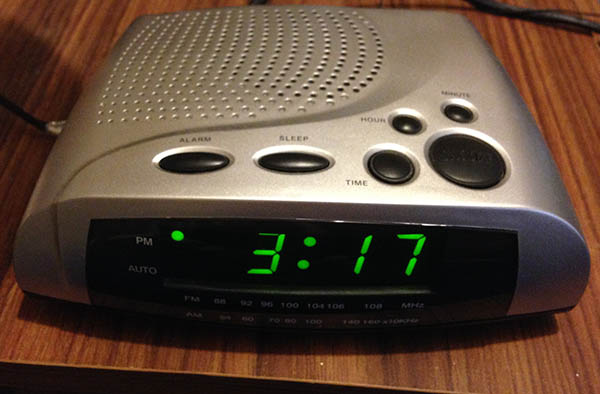
I still use a nightstand alarm clock as a backup just in case I don’t wake up from my phone alarm however the current alarm clock that I’ve had for years is a bit too bright at night so I end up having to cover it up or move it so I’ve decided that I might build my own which would allow me to turn off the display or dim it significantly by pressing the snooze button.
(video showing functionality)
The clock will be minimalistic, it will have 4 buttons: snooze/display off/on, alarm on/off/set alarm time while held down, hour and minute, LEDs for alarm on & PM indicator and just have a little buzzer as the alarm which we’ll PWM to a suitable tone of our choosing. We’ll use a medium sized 4 digit 8 segment LED display that I had bought from Ebay some time ago (ZTT-5461BS, common anode), the MCP7940M RTC and an ATmega48 which I had lying around which will have just enough I/O pins for our needs. I’m able to re-use some code from the LED clock project and I’ll also try out the RTC alarm functions.
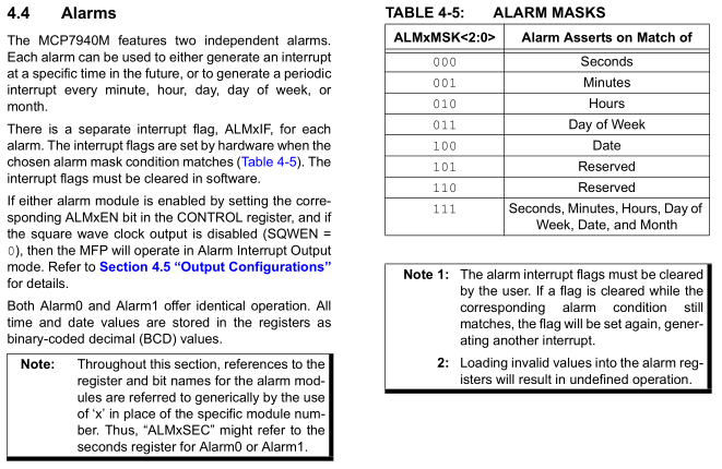
Lets look at the RTC alarm function first. The RTC has 2 independent alarms which can check if seconds or minutes or hours, etc match or if seconds and minutes and hours, etc match however you can’t say minutes and hours to match then trigger alarm 0. How it has to be done is to have each alarm do checking for 1 match only, so alarm 0 would do minutes matching and alarm 1 does hour matching. You could use ALMxMSK as 111 for matching everything however with my simple alarm clock we don’t keep track day of week, day and month.
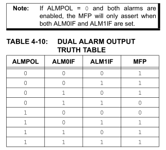
If alarm 0 does one part of the matching and alarm 1 does the other part, we need to select the output of the MFP pin to only change when both alarms match their number, so as the note suggests we have to set alarm polarity to 0, set ALM0IF and ALM1IF and if both match it will set the MFP open drain low.
if (PINB & (1<<ALARM_SET_BUTTON)) { // Changes to alarm
	// Load alarm hour/minute
	SoftI2cMasterAddress(RTC_ADDRESS, RTC_ALM0MIN, REPEATSTART);
	uint8_t alarmrtcMinutes = SoftI2cMasterRead(1);
	SoftI2cMasterStop();

	SoftI2cMasterAddress(RTC_ADDRESS, RTC_ALM1HOUR, REPEATSTART);
	uint8_t alarmrtcHour = SoftI2cMasterRead(1);
	SoftI2cMasterStop();

	uint8_t alarmAmPm = (alarmrtcHour & 0x20) >> 5;

	while (PINB & (1<<ALARM_SET_BUTTON)) {
		...
		ledDisplay[1] = alarmHour % 10;
		ledDisplay[2] = alarmMinutes / 10;
		ledDisplay[3] = alarmMinutes % 10;

		if (PINC & (1<<PC4)) { // Hours
			alarmHour++;
			...
		}
		if (PINC & (1<<PC5)) { // Minutes
			alarmMinutes++;
			...
		}
		if (alarmAmPm == 1) { // Am/pm
			PORTB |= (1<<PM_LED);
		}
		...
	}

	SoftI2cMasterAddress(RTC_ADDRESS, RTC_ALM0MIN, NOREPEATSTART);
	SoftI2cMasterWrite(alarmMinutes);
	SoftI2cMasterStop();

	SoftI2cMasterAddress(RTC_ADDRESS, RTC_ALM1HOUR, NOREPEATSTART);
	SoftI2cMasterWrite(alarmHour);
	SoftI2cMasterStop();

	// Alarm 0
	SoftI2cMasterAddress(RTC_ADDRESS, RTC_ALM0WKDAY, NOREPEATSTART);
	SoftI2cMasterWrite(RTC_ALMWKDAY_ALMMSK_MIN_MATCH);
	SoftI2cMasterStop();

	// Alarm 1
	SoftI2cMasterAddress(RTC_ADDRESS, RTC_ALM1WKDAY, NOREPEATSTART);
	SoftI2cMasterWrite(RTC_ALMWKDAY_ALMMSK_HOUR_MATCH);
	SoftI2cMasterStop();

	// Enable alarm 0 & 1
	SoftI2cMasterAddress(RTC_ADDRESS, RTC_CONTROL, NOREPEATSTART);
	SoftI2cMasterWrite(RTC_CONTROL_ALM0EN_BIT | RTC_CONTROL_ALM1EN_BIT);
	SoftI2cMasterStop();
Just to jump right into the code, when the alarm button is pressed, we load the alarm minute and hour from the RTC. While the alarm button is held down we can press the minute/hour buttons to increment them. We then save the minutes to alarm 0, hour to alarm 1, turn on the respective minute/hour matches and then enable both alarms.
You can then change the time quickly to match the alarm time and the alarm LED and buzzer will go off and continue that way even if the time changes, so the MFP pin keeps being pulled low. It seems that if the hour/minutes match, even if you clear the ALMxIF flag and the ALM0EN/ALM1EN bits, the MFP remains the same, only when the minutes or hours change does it take affect and go high again. This just means we’ll have to use another variable to keep track of whether the alarm is really on or off.
// Alarm going off
if (!(PINB & (1<<RTC_ALARM_MFP))) {
	if (alarmOn == ALARM_ON) {
		sbi(TIMSK2, OCIE2A); // Enable interrupt for buzzer
		displayOn = true;
	}

	if (PINB & (1<<ALARM_SET_BUTTON)) { // Turn off alarm
		alarmOn = ALARM_OFF;
		PORTB &= ~(1<<ALARM_ON_LED);

		cbi(TIMSK2, OCIE2A); // Disable interrupt for buzzer
		PORTD &= ~(1<<BUZZER);

		// Turn snooze timer off
		cbi(TIMSK1, TOIE1);
		TCCR1B = 0;
		TCNT1 = 0;
		timer1Counter = 0;

		_delay_ms(250);
	}
	if ((alarmOn == ALARM_ON || alarmOn == ALARM_SNOOZE) && (PINB & (1<<DISPLAY_OFF_OR_SNOOZE_BUTTON))) { // Snooze
		alarmOn = ALARM_SNOOZE;
		countMode = SNOOZE_COUNT;

		// Set snoozer timer for ~5 mins
		TCNT1 = 0;
		timer1Counter = 0;
		TCCR1B = (1<<CS12) | (1<<CS10);
		sbi(TIMSK1, TOIE1);

		cbi(TIMSK2, OCIE2A); // Disable interrupt for buzzer (the timer turns it back on after ~5 mins)
		PORTD &= ~(1<<BUZZER);

		_delay_ms(250);
	}
}
When the MFP pin goes low and the alarm was set, we turn on the match compare for the timer and turn on our LED display if it was off before. If we press the alarm set button, we’ll turn off the alarm completely so we turn off all timers. If the alarm snooze button is pressed, we switch the alarmOn variable to snooze so that we know not to sound the alarm when snoozing and use our timer to set snooze time to about 5 minutes and then it will sound the buzzer itself.
ISR(TIMER1_OVF_vect) {
	if (countMode == SNOOZE_COUNT) { // Snoozing, turn alarm on after 5 mins
		timer1Counter++;
		if (timer1Counter >= 30) {
			timer1Counter = 30;
			sbi(TIMSK2, OCIE2A); // Enable interrupt for buzzer
		}
	}
	else if (countMode == DISPLAY_OFF_COUNT) { // Display off, turn back on in 30 mins
		timer1Counter++;
		if (timer1Counter >= 214) {
			displayOn = true;

			// Disable this timer
			cbi(TIMSK1, TOIE1);
			TCCR1B = 0;
			TCNT1 = 0;
			timer1Counter = 0;

			if (alarmOn == ALARM_ON) {
				PORTB |= (1<<ALARM_ON_LED);
			}
			else {
				PORTB &= ~(1<<ALARM_ON_LED);
			}
		}
	}
	else if (countMode == BUZZER_ON_COUNT) { // Turn off alarm after 5 mins
		timer1Counter++;
		if (timer1Counter >= 30) {
			alarmOn = ALARM_OFF;
			PORTB &= ~(1<<ALARM_ON_LED);

			cbi(TIMSK2, OCIE2A); // Disable interrupt for buzzer
			PORTD &= ~(1<<BUZZER);

			// Turn timer1 off
			cbi(TIMSK1, TOIE1);
			TCCR1B = 0;
			TCNT1 = 0;
			timer1Counter = 0;
		}
	}
}
We use timer1 for counting a few things, none of which happen at the same time so we use a variable to keep track of what we’re incrementing. When the snooze timer reaches 5 minutes, we turn on the buzzer which also has a timed limit of 1 minute until we switch it off, if snooze is pressed again, we wait another 5 minutes.
if (PINB & (1<<DISPLAY_OFF_OR_SNOOZE_BUTTON)) { // Display off
	displayOn ^= 1;

	if (displayOn == false) {
		PORTD = 0x7F;
		PORTC &= ~((1<<SEG_COM1) | (1<<SEG_COM2) | (1<<SEG_COM3) | (1<<SEG_COM4));
		PORTB &= ~((1<<PM_LED) | (1<<ALARM_ON_LED));

		// Set timer for 30 mins
		...
	}
	...
For turning the display on or off via the snooze button, we just set the appropriate PORTs high or low to suit and set the timer for 30 minutes. I’m using 1K resistors on the LED display and 10K on the 2 LEDs, running from 5V makes the LED display pretty bright even at night time so I reduced it to 3.3V which is still a bit bright too, we could go all the way down to 1.8V if we really wanted to.
void display_led(void) {
	if (segmentUpto == 0) {
		PORTD = 0x7F;

		if (displaySet == DISPLAY_ON) {
			PORTC &= ~(1<<SEG_COM4);
			PORTC |= (1<<SEG_COM1);
		}
		else if (displaySet == DISPLAY_DIM) {
			PORTC &= ~(1<<SEG_COM4);
			DDRC |= (1<<SEG_COM4);
			DDRC &= ~(1<<SEG_COM1);
			PORTC |= (1<<SEG_COM1);
		}

		PORTD = (1<<PD7) ^ ~(number_to_led[(ledDisplay[segmentUpto])]);
	}
A trick we could do is turn on the internal pull-up resistor in the ATmega which is between 20K – 50K on the common anodes that we are driving high so when externally pulled low by the individual LED segments it will put that in series with the 1K resistors to make the LED display really dim but still readable when it’s dark though it makes some segments are slightly brighter than the others.
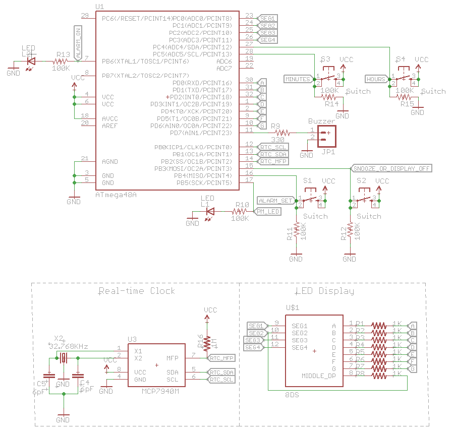
Here’s the schematic and how it all looked before I designed the case. Download Nightstand_Alarm_Clock_v1.1 (updated to fix alarm hour/minutes bug that would trigger the alarm if only hours matched when minutes had matched before hand, I changed ALMPOL to high when either alarm is activated and then we re-set them if both interrupts aren’t set)
3D Printed Case
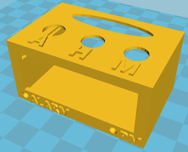
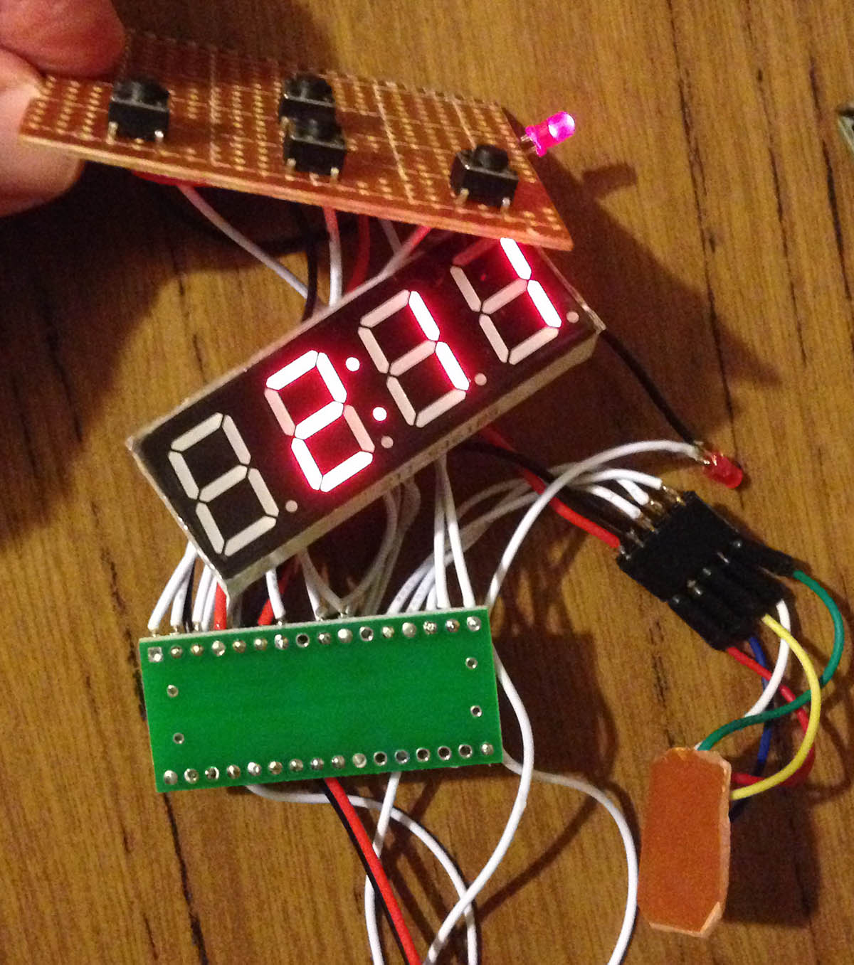
Now time for the 3D printed ABS case for it, I wanted it to be smaller than my current alarm clock so I made the case just a little bit bigger than the LED display and a long enough depth to fit all the buttons and electronics. The buttons were going to be a problem, should I just have buttons exposed on the case or have a cover to it? Should the buttons be very long so the PCB can be mounted on the bottom?
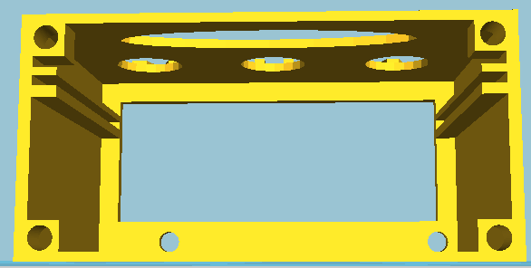
I opted for small buttons and for them to have a little button cover that would pop out a little bit. I designed the case so I could slide in a veroboard with the buttons positioned in just the right positions. I can also print out the text for the button and LEDs which are near the bottom. The back plate would be screwed into the case directly with 4x M3 screws.
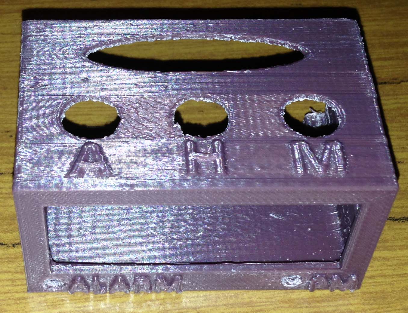
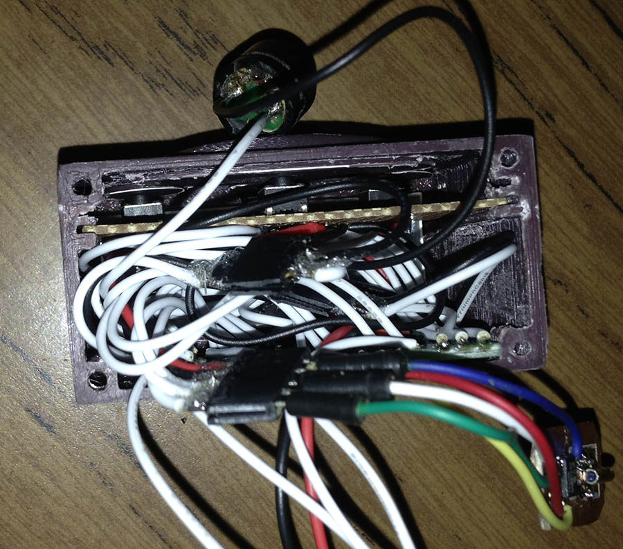
And here’s how it came out, in between where the button cut outs were, it doesn’t look very good, I could paint the whole case to cover up the imperfections and give it a style. I forgot to do a cut out for the power on the back plate but I just filed out what I needed and left the ISP connector in case I ever want to re-program it which I’ve done a few times already. I ended up having to just cram all the electronics into it, quite a tight fit, it would be nice to design a proper PCB for it all but it’s just a once off. It is kind of small and you could probably destroy it if you were to hit the snooze button way too hard :P. The project took longer than expected but overall I’m happy with the result.


