From the previous part, we designed a small power supply based on a Richtek DC-DC, added an 128X64 OLED display and gave it a quick test which it seemed to cover most voltage ranges with better increments than the old SPPS.
(sneak peak)
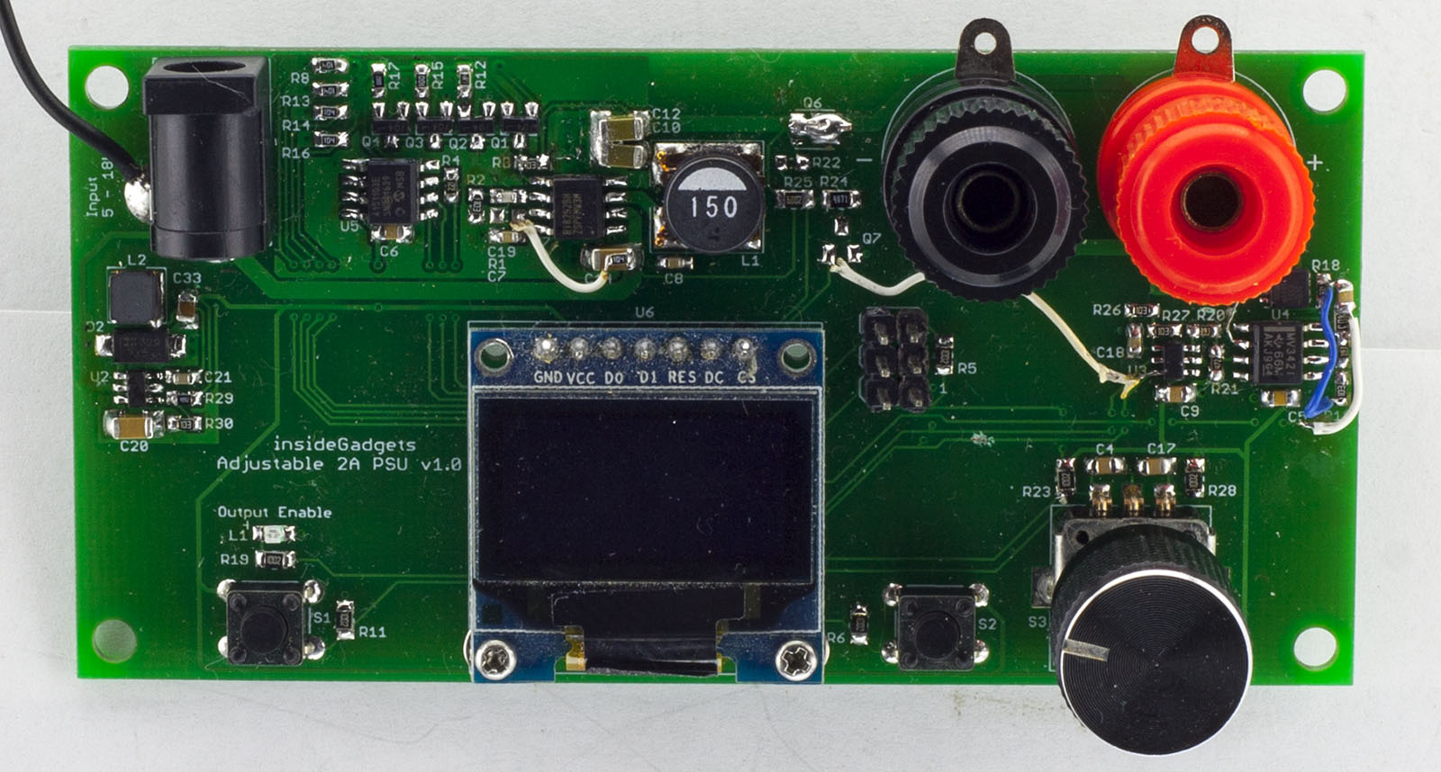
The PCB’s arrived and we’re ready to start populating each segment individually to make sure each part works. I put on the ATmega328 with the LCD, tested ok. Next was the main DC-DC converter with digital potentiometer and to test controlling it from the ATmega which seemed to work fine. One thing I hadn’t really paid attention to was that the DC-DC converter only goes up to supply voltage – 2V or so from my testing, the reference voltage starts to drop from the nominal 0.8V and it started to oscillate, so I might need a 18V power supply if I want up to 15V output.
Output Enable troubles
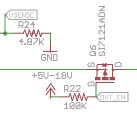
Next I soldered the P mosfet for the enable so I could enable or disable the output, that’s where things didn’t go as planned. I hadn’t considered the case where the power supply was set 2V and the gate was low, Vgs would only be -2V which is not enough to turn on the mosfet, you need something like -5V or higher to full switch it on, basically under 5V it was unusable, the mosfet would be dropping most of the voltage.
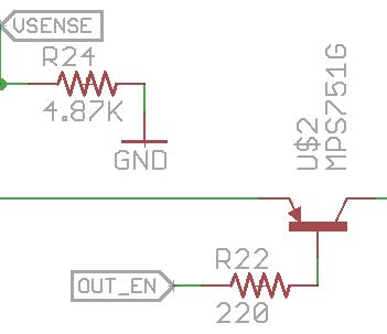
So I started looking for other alternatives, we could use a PNP transistor which is current driven rather than voltage driven, it seemed to work ok for lower voltages but was still getting a 0.1 or 0.2V drop across it. A small problem arises if the output goes to 15V, the 330 ohm resistor I was using for the base would be dissipating 600mW so you’d need a decent resistor for it.
We could use a voltage doubler to turn on an N mosfet but then there is a possibility over going over the Vgs max or we could use a dedicated DC boost circuit but that also has the same potential issue too. A small relay would be nice to use but they are usually pretty bulky, a solid state relay might work but looks like they are pricey and still a bit bulky for high load currents.
Another method is to use the N mosfet with a bootstrap which raises the gate as much as the source due to the capacitor. You have to let the diode charge the capacitor first, then switch on the gate via that capacitor (I used an opto-coupler) and you also need a way to turn it off, I used a NPN connected to the gate.
Firstly I tested this all on a TO-220 style mosfet the STP16NF06 which gave promising results, Vds of 0.01V but then it slowly started rising up until it switched off. Then I tried the mosfet I was going to use for my current control, the IRFHM8334 and that gave better results, it stayed at 0.01V for a few minutes without any issues, so it works.
This is quite a bit of added circuitry just for output enable control, you would have to make sure the NPN was switched on at all times, then switch it off when you wanted to enable the output and also switch on the opto-coupler a few milliseconds after. Getting to this point took a while but in the end I decided to skip the output enable for this power supply, too many more components for a feature which isn’t that useful in this small power supply.
Current Limiting
It was now time to put together the current limiting side, I was getting ready to put the 12bit DAC ready in it’s place, checked over the datasheet for the pins when I noticed that the SOT23-6 footprint was wrong, pins 1 & 3 were flipped, same with 4 & 6, argh! I hadn’t actually checked the pins on the footprint but luckily we can just flip the chip dead bug style, gently pull the legs back and solder it on and it worked fine.
I started to test a 12V fan and noticed that the current reading was jumping around quite a bit, averaging the ADC values helped a little but something wasn’t right. I tried some 1 ohm resistors and they didn’t seem anywhere as bad as the fan which is an inductive load, to the scope we go.
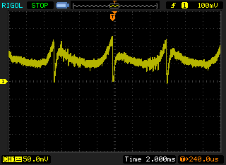
It looks like there is pretty bad noise on the op-amp output after it’s times-ed by 4.
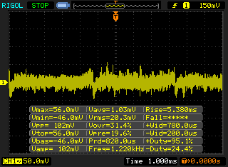
When probing the current sense resistor, you can sort of see it there as well.
We can either try adding a capacitor on the op-amp feedback loop (something more than 1uF seems to help) or we can add a low pass filter directly after the sense resistor or on the op-amp output.
Initially I tried it right after the sense resistor but testing LEDs when current limiting was on, at 5V with 10mA current, the LEDs would eventually die out when I was manually pulsing the LED, as the low pass filter is affecting the op-amps ability to quickly limit the current so I put the low pass filter on the op-amp output instead. Strange enough when making this modification, the op-amp seemed to have been damaged, maybe ESD or similar but the op-amp was reading 16mV output when the input was 0mV, swapped out the op-amp and it’s back to normal now.
DC-DC for 5V
Lastly I need 5V for the MCU, op-amps, display, etc but didn’t want to go for an LDO like I did last time and was holding out for a few months for a small Richtek DC-DC converter but they never came in stock.
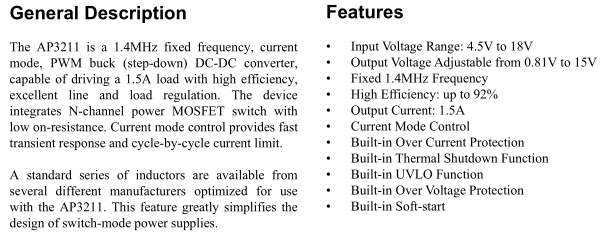
So I ordered an BCD AP3211 which looks like it should do the job, 4.5V to 18V input, output adjustable 0.81V to 15V, 1.5A output current, 1.4MHz frequency which allows us to use a small inductor but unlike the Richtek’s, we will need to use a diode. The AP3211 costs 40c for 25 units.
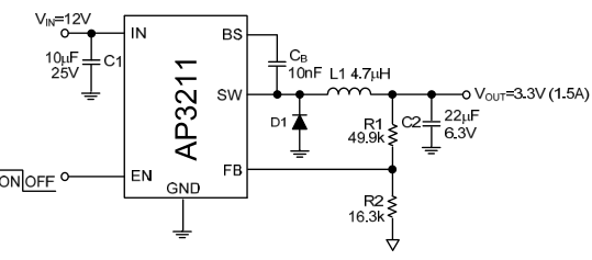
The schematic looks like any other DC-DC, compared to the usual 8 pin Richtek, we don’t have a compensation resistor or capacitor, don’t have a soft start capacitor and only need 1 output capacitor instead of 2.
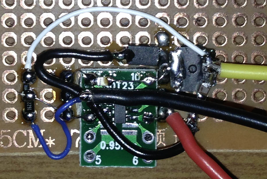
I gave it a test on some perfboard at 3.3V with 4.7uH and it seemed to function without any problems with a 1 amp load so I decided to add this as our 5V regulator. The diode I went with (40V 3A SBR3A40SAF) was overspec’ed and a bit large but it doesn’t matter too much as we have a good amount of room to work with and price was decent at 13c each. I think I will use this as my go to DC-DC, a small footprint but probably should give it a test with the scope to see how it really performs.
Software
We already have the SSD1306 screen working with the ATmega so let’s jump into the other code.
update_voltage_dpot_mosfet();
update_current_limit();
_delay_ms(10); // Wait a bit to adjust

// 10 samples of voltage and current to average
uint16_t adcVoltageAverage = 0;
uint16_t adcCurrentAverage = 0;
for (uint8_t x = 0; x < 10; x++) {
	adcVoltageAverage += adc_read(7);
	_delay_ms(1);
	adcCurrentAverage += adc_read(6);
	_delay_ms(1);
}
adcVoltageAverage = adcVoltageAverage / 10;
adcCurrentAverage = adcCurrentAverage / 10;
uint16_t adcVoltage = (int) (double) adcVoltageAverage * (double) 0.00107421875 * (double) 14.7 * (double) 100;
uint16_t adcCurrent = (int) (double) adcCurrentAverage * (double) 0.00107421875 * (double) 2 * (double) 1000;

// For display
voltageNumber = adcVoltage;
currentNumber = adcCurrent;
In our main while loop, we update the set voltage by updating the digital pot and the mosfets controlling the resistors, wait a little bit for the DC-DC to settle down and then we can average the ADC samples for voltage and current. The 14.7 and 2 multipliers are set in accordance to resistor divider for the voltage and current.
// If calibrated, update the dpot / mosfet values
if (calibrated == true) {
	dpotValue = calibrationValues[calibrationCounter][0];
	mosfetEnabled = calibrationValues[calibrationCounter][1];
}

// Dpot value / mosfet enabled changed?
if (dpotValue != dpotValueOld || mosfetEnabled != mosfetEnabledOld) {
	PORTD &= ~(1<<DPOT_CS);
	spi_write_msb((DPOT_WIPER0 << 4) | (DPOT_WRITEDATA << 2));
	spi_write_msb(dpotValue & 0xFF);
	PORTD |= (1<<DPOT_CS);

	// More resistance = voltage goes higher
	if (mosfetEnabled == 0) {
		PORTD |= (1<<EN_20_OHM);
		PORTD &= ~((1<<EN_10_OHM) | (1<<EN_4_7_OHM) | (1<<EN_0_OHM));
	}
	...

	dpotValueOld = dpotValue;
	mosfetEnabledOld = mosfetEnabled;
}

// Update the current limit
void update_current_limit(void) {
	// Current limit changed?
	if (currentLimit != currentLimitOld) {
		soft_i2c_write_2_bytes(DAC_ADDR, WRITE_DAC_REG | ((currentLimit & 0xF00) >> 8), (currentLimit & 0xFF), DAC_SCL, DAC_SDA);
		currentLimitOld = currentLimit;
	}
}
In the update voltage function, if the power supply was calibrated we use the calibration values of the DPot and mosfet resistors to change the voltage, then just update the DPot and switch the mosfets on or off. The current limit function just updates the I2C DAC.
// Calibration
if (inCalibration == true && waitForLowVoltage == false) {
	if (adcVoltage > adcVoltageOld) { // If voltage is higher than old voltage, add to array
		adcVoltageOld = adcVoltage;

		if (calibrationCounter < 400) {
			calibrationValues[calibrationCounter][0] = dpotValue;
			calibrationValues[calibrationCounter][1] = mosfetEnabled;
			calibrationCounter++;
		}
		...

	// Increment dpot / mosfets if voltage doesn't drop by more than 200mV.
	int voltageDrop = (adcVoltage - adcVoltageOld);
	if (dpotValue < 253 && voltageDrop >= -200) {
		if (mosfetEnabled < 3) {
			mosfetEnabled++;
		}
		else if (mosfetEnabled >= 3) {
			dpotValue++;
			mosfetEnabled = 0;
		}
	}
	...
}
The calibration function is similar to the SPPS one, we wait until the voltage drops below 2V, then slowly start increasing the voltage and recording the values into the array if the voltage has changed. I probably should add some sort of current calibration as well. There is a case where setting the DPot too high causes the DC-DC to drop out so we have to monitor that the voltage doesn’t drop by too much, if it does, then we have reached the limit.
// In current section, increase voltage if needed to match current limit
if (selectedOption == CHANGE_CURRENT) {
	currentLimitCalc = currentLimit / 1.6;
	int currentDifference = currentNumber - currentLimitCalc;

	if (currentNumber >= 5 && (dpotValue < 240 || calibrationCounter < calibrationLimit)) {
		// Large differences
		int largeDifference = currentNumber / -10;
		while (currentNumber >= 50 && currentDifference <= largeDifference && (dpotValue < 240 || calibrationCounter < calibrationLimit)) {
			if (calibrated == false) {
				if (dpotValue < 240) { // See which pin is low
					dpotValue++;
				}
			}
			else { // Calibrated
				if (calibrationCounter < calibrationLimit) {
					calibrationCounter++;
				}
			}

			update_voltage_dpot_mosfet();
			update_current_limit();
			_delay_ms(10);

			voltageNumber = (int) (double) adc_read(7) * (double) 0.00107421875 * (double) 14.7 * (double) 100;
			_delay_ms(1);
			currentNumber = (int) (double) adc_read(6) * (double) 0.00107421875 * (double) 2 * (double) 1000;

			currentLimitCalc = currentLimit / 1.6;
			currentDifference = currentNumber - currentLimitCalc;
			display_screen();
		}

		// Small differences
		if (currentNumber <= 500 && currentDifference <= -3) {
			if (calibrated == false) {
				if (dpotValue < 240) { // See which pin is low
					dpotValue++;
				}
			}
			else { // Calibrated
				if (calibrationCounter < calibrationLimit) {
					calibrationCounter++;
				}
			}
		}
	}
}
The other large part of the code is the current limiting, we need to always be adjusting the voltage higher or lower depending on whether the current limit has been hit and to not jump around too much. The op-amp controlling the N Mosfet will only allow a certain amount of current to pass so if we increase in voltage by too much, the N Mosfet will be taking the voltage drop hit.
Firstly after playing around with calibrating the current, I found that I had to divide the output value to the DAC by 1.6 to get a somewhat accurate current limit. Once we have that, we can calculate how much we are under the current limit (negative result). We only increase the voltage if we see a load current at least 5mA, otherwise the voltage would keep increasing if nothing was plugged in.
There are two parts, first for regulating large current differences and smaller ones. For the larger differences, we only enter if the current is over 50mA and if the difference is more than the current divide 10. By not pre-defining the current difference, this gives us better control to deal with current fluctuation which if not handled correctly could lead the voltage to oscillate. For example, at 1A current, you wouldn’t want a small 20mA change in current to enter this loop, update the DPots, DACs, etc and stay until it reached the current limit as soon after the reverse would happen as you were 20mA over the current limit.
For smaller differences of 3mA and if we are under 500mA of current, we just increase the voltage by one notch, it will slowly regulate the voltage up over time. If we are over the current limit, the code is pretty much the same as above except that everything is the opposite.
Apart from that, there isn’t too much else to it but the system as a whole did take a few days to test and verify it’s operation.
Testing DC-DC
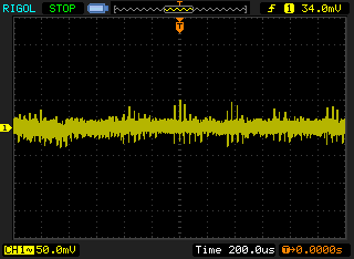
Now it was time to put the DC-DC output on the scope and see what we get.
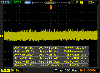
With no load it doesn’t look too bad.
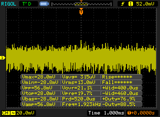
But once a small load such as 100mA is applied at 2V, it jumps to 300mV peak to peak.
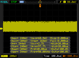
When I increased the voltage to 2.8V, it drops to 60mVpp with an 800mA load (2x 1 ohm resistors in series). Then I tried changing the 10K feedback resistor to 20K, now it’s powering up at 2.8V minimum instead of 1.8V like it used to with 10K but the issue occurs until 3.3V now. If we go lower to 4.7K, we get a 1.3V minimum and the issues occurs until 2V but we lose some of our step resolution at the higher voltages. I put the feedback divider for the DC-DC as 10K/10K to rule out the existing feedback solution (DPot / Resistors) but I still got about 150mVpp of noise.
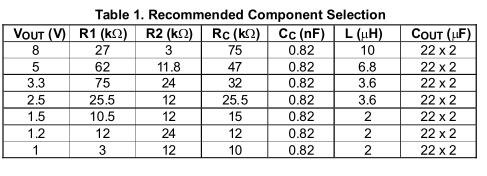
So I started building up the DC-DC on another PCB which I had used the DC-DC 340KHz version and I saw the same noise. The first thing I thought to try was to change the compensation resistor as there really couldn’t be anything else but it shouldn’t have really affected it this badly I thought.
Well it turns out it did, I changed it from 75K to the lowest 10K value they recommended for the minimum output of 1V solved the issue, so everything is now working.
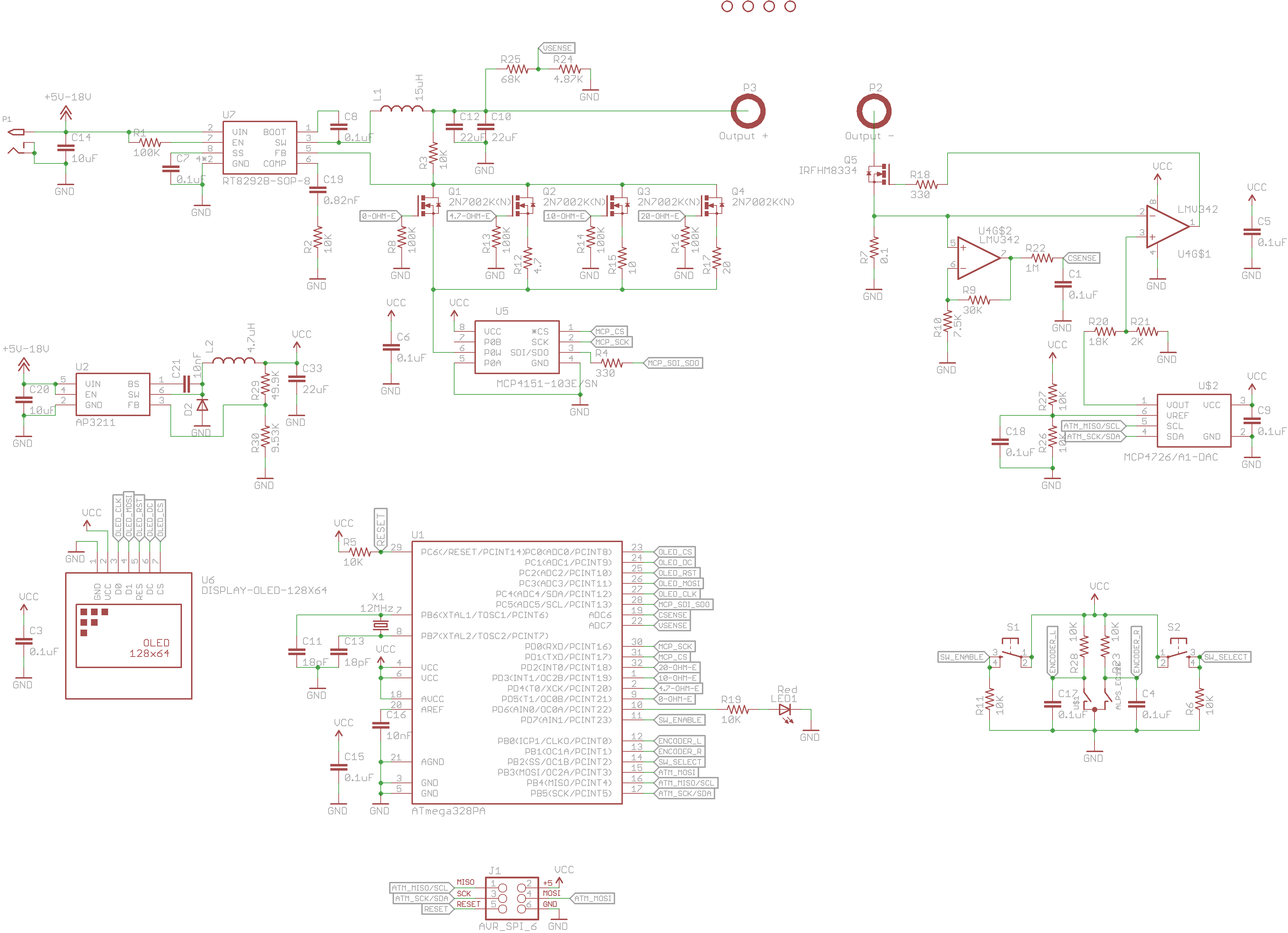
Here’s the full schematic after all the fixes have been made.
Download Adjustable_2A_PSU_v1.0


