As part of the Mini Temp Logger design I need to look at a better way of keeping time other than using the watchdog timer as it’s fairly inaccurate. I stumbled across the Microchip MCP7940M Real-time clock controllable by I2C, you can set alarms, a clock output (likely what I might use for my project), ability to trim the oscillator in 1PPM increments (129PPM -/+ range), low power consumption at 1.2uA and the price was $1.
Choosing capacitors
This RTC recommends the use of 6-9 pF 32.768KHz crystals, the most common/cheap ones are 12.5pF and it still does work with them but it won’t be as accurate as the 6-9pF ones (and for me it sometimes stopped working), it took me a while to realise this as I was reading the preliminary datasheet for a while.
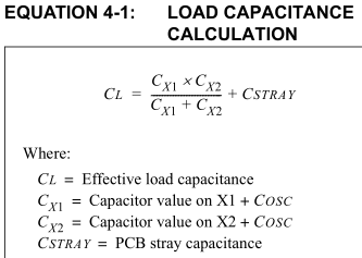
The first thing we need to do is calculate the capacitors we’ll require for our crystal, there is a standard formula which we follow for this, Cstray is usually between 2-5pF so lets assume ours will be half way at 3.5pF. I went with a low cost (at the time) EuroQuartz MH32768L crystal that has a CL of 6pF. The best match for our formula is 6pF for CX1 and CX2: (6 pF * 6 pF)/(6 pF + 6 pF) + 3.5 pF = 6.5pF which is close to our CL of 6 but you may have to vary the capacitors depending on your testing.
Interfacing
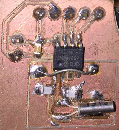
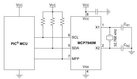
I built a simple PCB for the RTC (doesn’t look the best as I built it about 6 months ago when I didn’t use to sand the PCB) but there isn’t much to it. We just need a crystal with 2 caps, a cap for the chip and then just I2C resistor pull ups. Let’s interface with it, I’ll start off using the Arduino and we’ll move to an ATmega328 later on.
Wire.beginTransmission(rtc_address);
Wire.write(0x00);
Wire.write(0x80);
Wire.endTransmission();
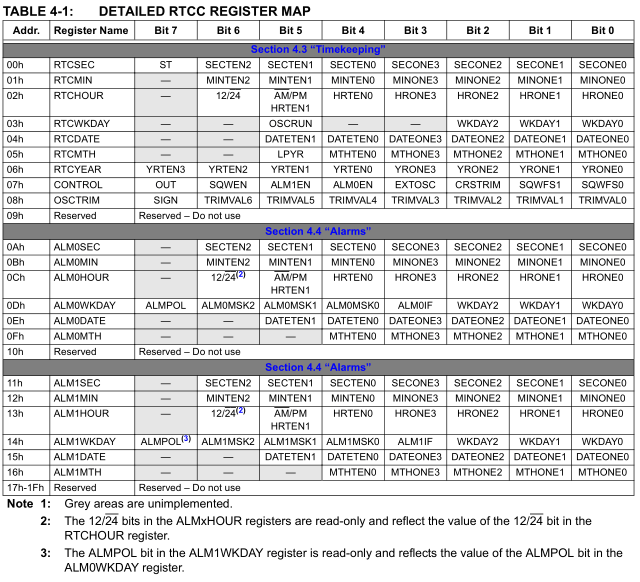
We have the memory mapping available to us from the datasheet, the first thing to do is need to turn on the oscillator by turning on the ST bit in the RTCSEC register.
seconds = (Wire.read() & 0x7F);
minutes = (Wire.read() & 0x7F);
hours = (Wire.read() & 0x1F);
day = (Wire.read() & 0x07);
date = (Wire.read() & 0x07);
month = (Wire.read() & 0x07);
year = (Wire.read() & 0x07);
By default the time starts at 00:00:00, to read out the date/time you need to access a few registers.
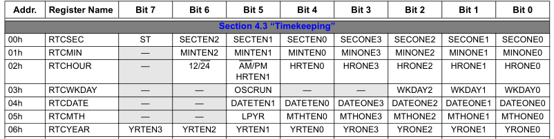
Notice how the bits are arranged in the registers, it isn’t quite a seconds to binary mapping, normally 35 seconds would translate to 100011 but instead they have 3 bits to keep track the 10’s in the seconds (11 in our case) and 4 bits for the 1’s in the seconds (101 in our case). It’s a little strange how they have it that way because doing a second to binary mapping would actually save them 1 bit. We can also write the date/time to the same registers that we read them out from.
Testing, Trim and Multifunction Pin
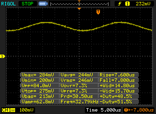
Now it’s time for testing, depending on your PCB you may have to vary the capacitors slightly, for a RTC it’s best to leave it for a day or two to see how far it varies from real time. You can try and use a scope to measure the frequency to see if you are near the frequency but you need to take account that the scope probe will add an extra capacitance, for mine it’s 15pF. As you can see the voltage is very low which I guess is how they keep it low current.
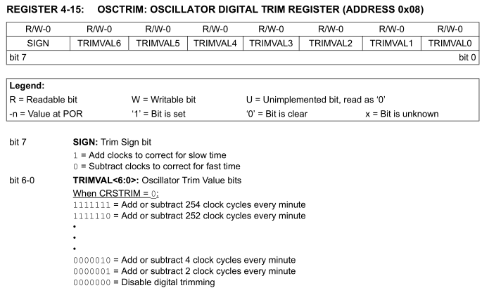
Once the right capacitors have been found, we can trim the oscillator to make it even more accurate and have it run for a few days or weeks. There are 2 different trimming options available to us, either trim once cycle per minute or once cycle per second, we’ll use once per minute as in my testing I’ve only found it drifting a second or two every few days so we don’t need too much trim.
Wire.beginTransmission(rtc_address);
Wire.write(0x08);
Wire.write(160);
Wire.endTransmission();
We set the sign bit to add or subtract cycles, for me I needed to add cycles as it was running slower and then we set the cycles to add/remove, I needed 32 more cycles so I send the number 160. You’ll need to leave it for at least a 1 week to really test how much more trimming you need.
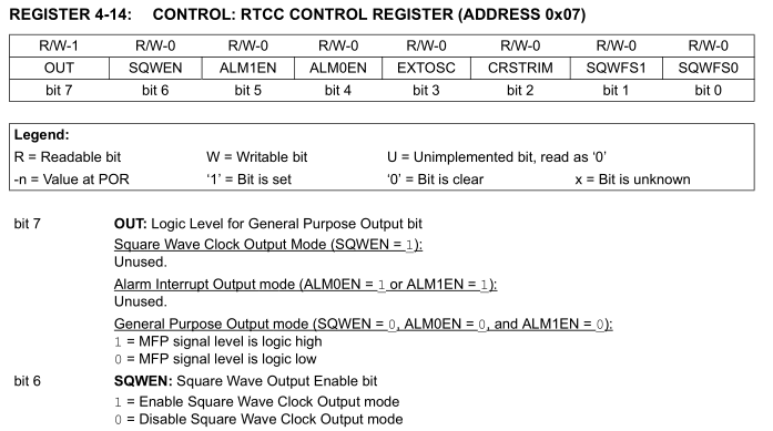
With the multi-function pin, the square wave clock output is what I’ll need to look at for my Mini Temp Logger project so it could wake up the AVR every second. It’s an open-drain pin so we’ll stick in a 10K resistor to VCC and tap off the pin to our AVR. We divide the clock down from 32.768KHz to 1Hz by leaving the SQWFS set to 00 and enabling the output by setting SQWEN to 1, now we’ll receive a pulse 1 every second.
Download the Arduino MCP7940M_Test
Software & Putting it all together
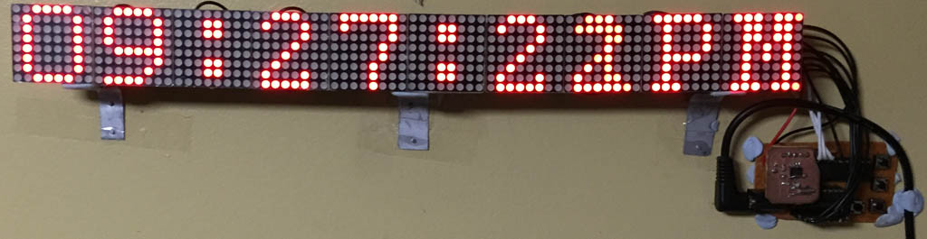
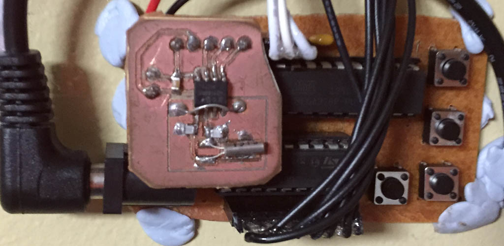
I decided to use my 10x 8×8 LED matrix as the display for the time so we’ll just need to make a few modifications to the existing code to interface with the RTC. Since I had the RTC in a small PCB I just use pin headers to connect to it and I’ll add some buttons to program the time and the RTC delay. I was thinking if I should make it battery powered but it drew about 15mA so I decided to add a DC jack and just use a wall adapter. I was going to cover everything with acrylic but I didn’t have a long enough sheet so it’s just bare at the moment.
// Init Timer
TCNT0 = 0; // Reset to 0
TCCR0A = (1<<WGM01);
TCCR0B = ((1<<CS02) | (1<<CS00)); // 256 prescaler
sbi(TIMSK0, OCIE0A); // Enable overflow interrupt
OCR0A = 125;
...

ISR(TIMER0_COMPA_vect) {
	light_LEDs();
}
...

// Check if changed
if (hoursTen != ((hours & 0x10) >> 4) + 30) {
    hoursTen = ((hours & 0x10) >> 4) + 30;
    modify_leds(1, hoursTen);
}
if (hoursOne != (hours & 0x0F) + 30) {
    hoursOne = (hours & 0x0F) + 30;
    modify_leds(2, hoursOne);
}
...
if (timePm != ((hours & 0x20) >> 5)) {
    timePm = (hours & 0x20) >> 5;
    if (timePm == 1) {
We have a timer to update the display as it’s easier that way so I don’t have to worry about meeting any timing and I’m only updating the numbers if they have changed which saves us from having to convert a number into the LED pattern every time. There’s a bit of code needed to change the seconds/minutes/hours into a readable format and we also check the AM/PM bit.
if ((PINB & (1<<PB4 | 1<<PB1)) == (1<<PB4 | 1<<PB1)) {
	rtcCal++;

	SoftI2cMasterAddress(RTC_ADDRESS, 8, NOREPEATSTART);
	SoftI2cMasterWrite(rtcCal);
	SoftI2cMasterStop();

	modify_leds(1, C);
	modify_leds(2, A);
	modify_leds(3, L);
	modify_leds(4, (rtcCal / 100) + 30);
	modify_leds(5, ((rtcCal / 10) % 10) + 30);
	modify_leds(6, (rtcCal % 10) + 30);
	...

	_delay_ms(200);
	resetDisplay = true;
}
Apart from that we just have the code for changing the trim and also the timer OCRA if needed, all pretty basic. I check the RTC every 50ms which is probably a bit much however if you only check once every half a second or so, then you can sort of notice a delay in the display when it updates the seconds kind of like it’s updating it once every 1.5 seconds. Download 8x8_x10_LED_Clock_v1.0
After leaving it running for 2 months it’s just 2 seconds slow, if it drifts another second I’ll bump up the trim but I’m pretty happy how it turned out. It’s much more accurate than our microwave; that drifts what seems to be 1 minute every month.


