From our previous part, we designed a client with the nRF24 which communicates the LiPo battery cell voltages to a server running from an ESP8266 so we could easily jump onto it and check the cell voltages. In this part we’ll add in email alerts with adjustable battery voltage thresholds, add an easy server setup process to join your Wifi and give the system a test.
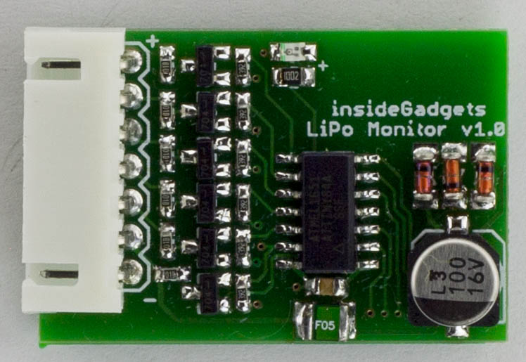
First things first, the client PCBs arrived (34 x 23mm), built one up and it worked well. I sprayed the board with PCB lacquer and put clear heat shrink over it. When trying to link it up to the server, it wasn’t working, seemed to just stay waiting to receive the packet from the server. I eventually found out that I had to bump the voltage up to at least 3.9V for it to link up properly, I’m guessing the 3 diodes dropping the voltage down is part of the issue when listening as it can take quite a bit of current. Sending a packet when it checks in works fine at lower voltages. When ATtiny and nRF24 are sleeping, it takes about 6uA so I’m happy with that.
I was thinking about redesigning the board to make it even smaller (32 x 16mm) if you just had up to a 4 cell battery, it would be a little bit harder to build.
Adding email alerts and voltage threshold
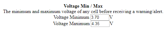
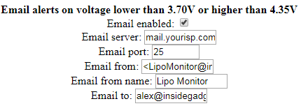
This monitoring system has to have email alerts but also a low/high voltage threshold would be nice, so you could receive an alert if the battery dropped below 3.7V or if you forgot to discharge the battery and it was at 3.9V or higher.
voltageMin = server.arg("voltage-min").toFloat();
voltageMax = server.arg("voltage-max").toFloat();
...
EEPROM.put(EEPROM_LOCATION_VOLT_MIN, voltageMin);
EEPROM.put(EEPROM_LOCATION_VOLT_MAX, voltageMax);
EEPROM.commit();
...
EEPROM.get(EEPROM_LOCATION_VOLT_MIN, voltageMin);
EEPROM.get(EEPROM_LOCATION_VOLT_MAX, voltageMax);
I’ve added both of these to the admin page and all settings are saved to the EEPROM, it was all pretty straight forward like we’ve done before. The only thing that I was wondering how to proceed with was storing the voltage min/max float to the EEPROM but it looks like there is a function for that, EEPROM.put and EEPROM.get, I had to leave about 10 bytes in between each float variable.
// Clear alerts automatically after 24 hours of a sent email
if (emailEnabled == 1 && sensorList[sensorNo].emailSent == 1) {
	if ((currentUptime - sensorList[sensorNo].emailSentTime) > 86400) {
		sensorList[sensorNo].emailSent = 0;
	}
}

// If email alert enabled, check voltage on cells
if (emailEnabled == 1 && sensorList[sensorNo].emailSent == 0) {
	for (uint8_t v = 0; v < cells; v++) {
		if (sensorVoltage[sensorNo][v] <= voltageMin || sensorVoltage[sensorNo][v] >= voltageMax) {
			char emailSubject[30];
			char emailText[50];
			char cellVoltage[10];
			dtostrf(sensorVoltage[sensorNo][v], 4, 2, cellVoltage);

			sprintf(emailSubject, "LiPo Warning - Bat #%i", sensorNo);
			sprintf(emailText, "Cell %i at %sV", v+1, cellVoltage);
			...
			break; // Don't send any more for this battery
		}
	}
}
As part of the email alerts, we have to keep track of when the alert has been sent so we don’t send duplicate alerts when the client checks in. We’ll add a emailSent element to each battery for this and reset it once every 24 hours.
Simple Logging
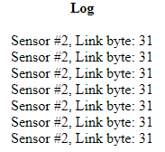
It’s useful to have some sort of logging even if it’s just basic information, I decided to just keep track of the sensor number and the link byte being sent to the server. It’s just an array of 50 elements and accessible via the /log page, once over 49 entries it will clear the log.
Easy server setup process
So I was thinking about how to make the server setup easier so that you wouldn’t have to program it with the Wifi SSID and password beforehand, most of the time with these sort of devices, the device starts off as an access point which you connect to and then enter in the SSID and password so that’s what I’m going with.
// If button is held when booting or if setup byte in EEPROM is 255, boot AP mode
uint8_t deviceSetup = EEPROM.read(EEPROM_LOCATION_DEVICE_SETUP);

if (digitalRead(ap_mode_pin) == 1 || deviceSetup != 1) {
	Serial.println("\nAP Mode");
	IPAddress Ip(192, 168, 0, 1);
	IPAddress NMask(255, 255, 255, 0);
	WiFi.softAPConfig(Ip, Ip, NMask);

	WiFi.mode(WIFI_AP);
	WiFi.hostname("LiPoBatMon");
	WiFi.softAP("LiPoBatMon-AP", "1928472742"); // Change this for every device

	server.on ( "/", handleAP );
	server.on ( "/style.css", handleCss );
	server.onNotFound ( handleNotFound );
	server.begin();
...
We can have the device check an EEPROM byte to see if the device has been setup and/or if a button is held down, it will switch to the AP mode. We give it a default IP of 192.168.0.1 and set it up with it’s AP name as LiPoBatMon with a password. The password would have to be pre-programmed, be labelled on the unit but also be different for each unit. Some of the devices that act as an AP when being setup have no password at all but that’s probably not a good idea to do.

Once we connect to the AP, we just enter in the SSID and password like you would, it saves these to the EEPROM and also loads some default values to the EEPROM too. The device then needs to be rebooted and it will then start in station mode.
Serial.println("\nStation Mode");

// Load Wifi SSID and password from EEPROM
int eepromCounter = 0;
for (uint8_t x = 0; x < 50; x++) {
	wifiSsid[x] = EEPROM.read(eepromCounter++);
}
...
// Load settings
emailEnabled = EEPROM.read(eepromCounter++);
...

WiFi.mode(WIFI_STA);
WiFi.hostname("LiPoBatMon");
WiFi.begin (wifiSsid, wifiPassword);

// Wait for connection
Serial.print("Connecting to Wifi");
while (WiFi.status() != WL_CONNECTED) {
  delay(500);
  Serial.print(".");
}
MDNS.begin("LiPoBatMon");
...
When started in station mode, we load up the SSID and password from the EEPROM as well as the other settings, connect to the Wifi and lastly set our hostname with MDNS which would allow PCs on the local network to resolve the DNS name given otherwise we might have no other easy way to find the IP it was assigned.
Testing
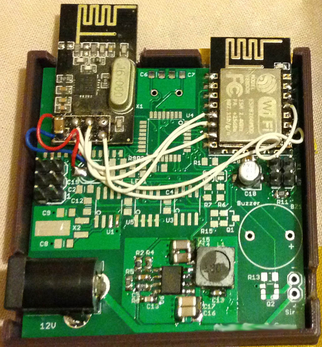
I built up a server using one of my other boards which had used the ESP8266 and haven’t had any issues with it. Download LiPo_Battery_Monitor_v1.1
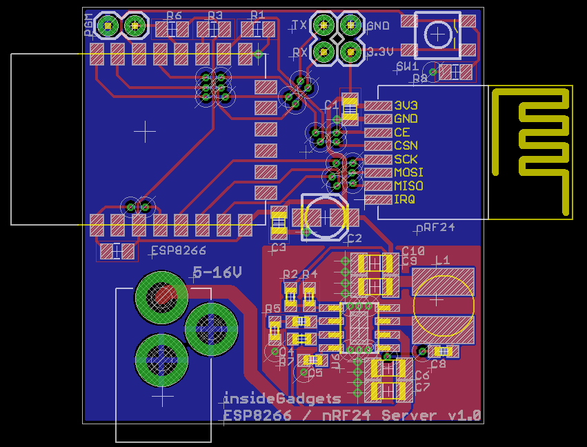
The server board has been designed, I’ll just have to send it off if I do wish to make this project into a product. I think it would make sense if the clients were low cost to buy (say a few dollars each) but that would only really be possible if you built them yourself.
From some tests, I found that the server has to be relatively close to the clients, having batteries in an enclosed metal box wasn’t great while also having them in a LiPo bag pretty much killed the client check-in. I also store LiPos in masonry blocks with a cover and didn’t have any check-in issues with those ones.
So what I would really use this monitor for is for batteries that don’t get charged as often, for me, it would be the older 2S/3S packs from which I started from and some which I use time to time for RC cars.


