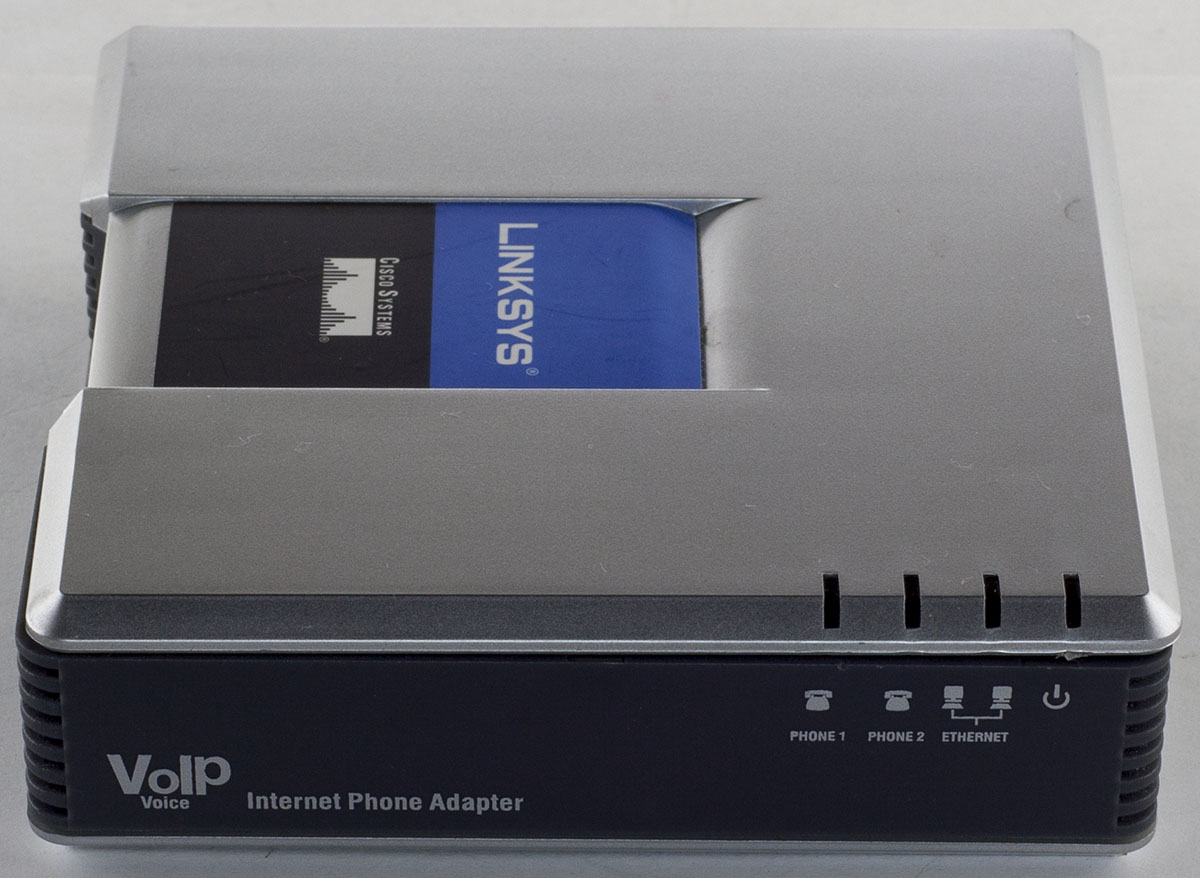
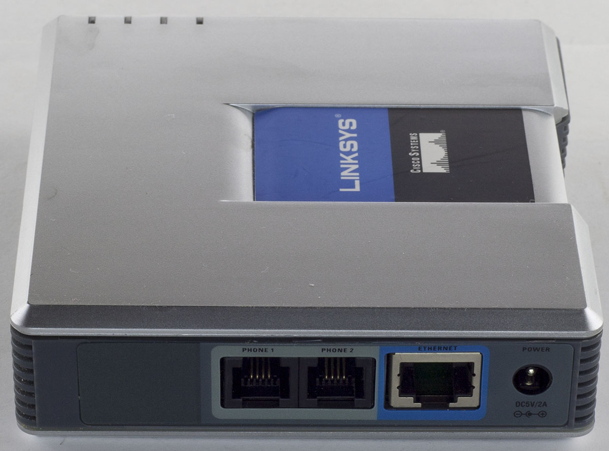
Today we’ll be taking a look at the Linksys PAP2 VoIP Phone Adapter which has an Ethernet port and 2 phone ports for analog phones, powered using a 5V adapter.
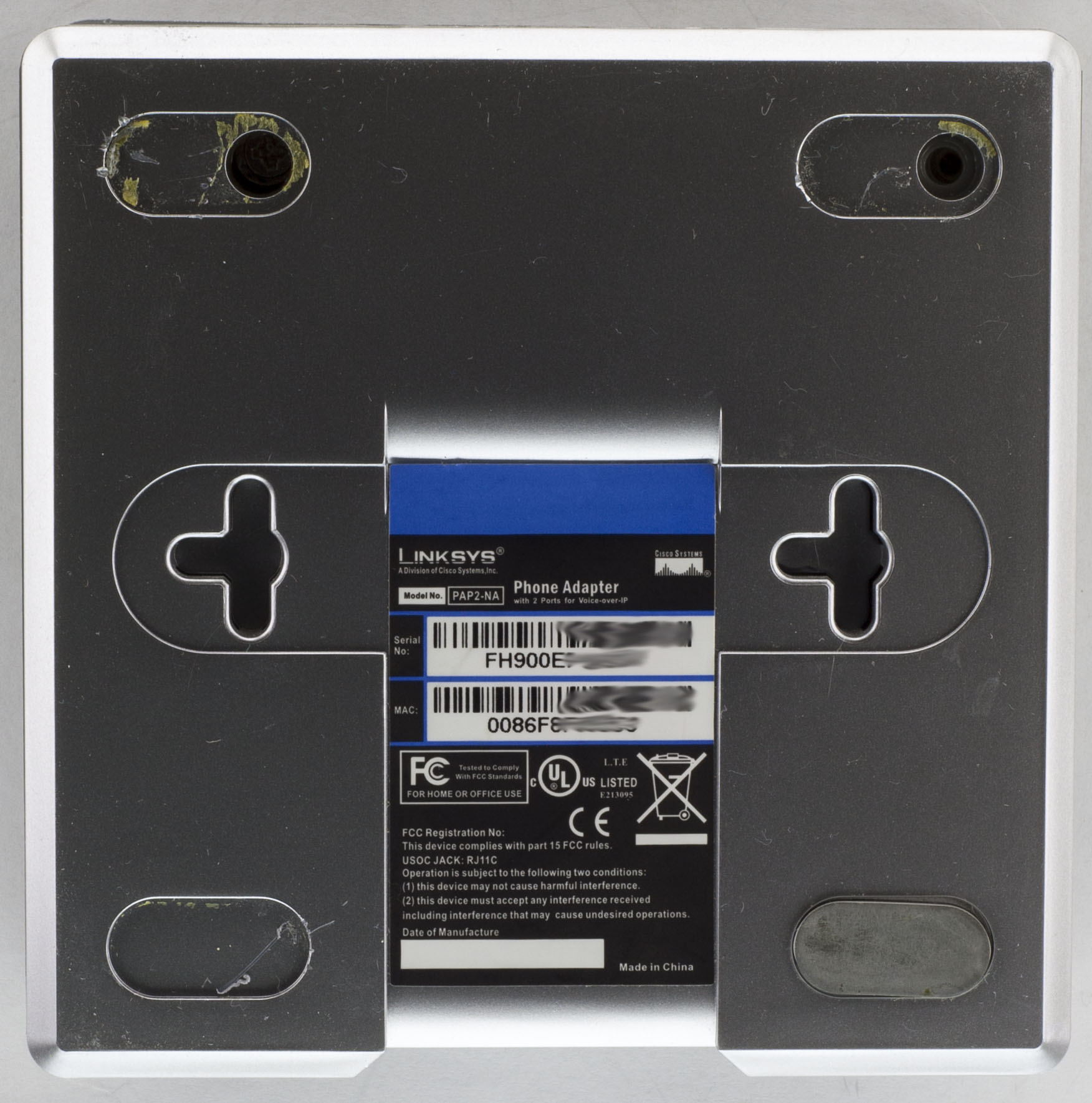
2 screw at the back, 1 screw on the side and we’re in.
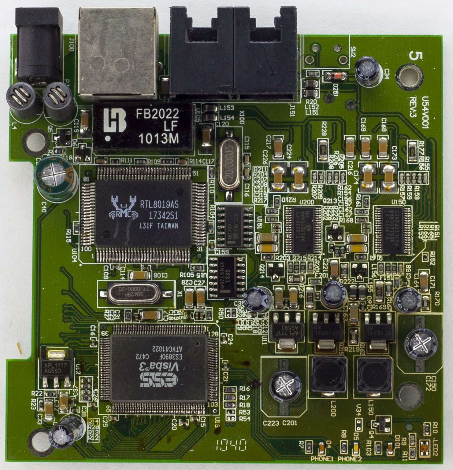
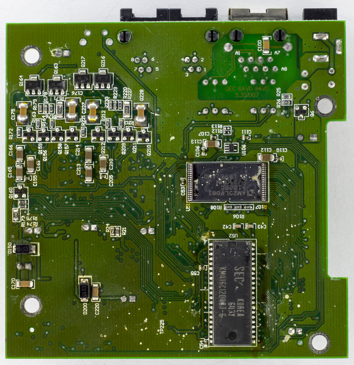
We have a 2 chip solution – the main chip and LAN controller. The bottom of the board looks like it’s seen better days and there are some spots around the board that looks like burn marks, not sure if someone else has opened this up before. For the power side, there are 2 chokes before going through a PNP transitor to a 470uF capacitor and we have 2 AP1117 LDOs giving out 2.5V and 3.3V. There are 2 logic chips around as well, an LS32 a quad OR gate and a HC74 Dual D Flip-Flop with S/R. PCB date code is 40th week of 2010.
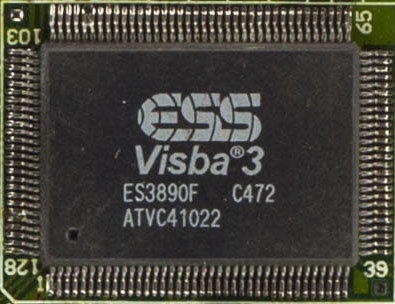
The main chip is a ESS ES3890F which is marketed as a Video CD Processor which is a little odd that they chose it for this application but it must have offered what they needed. There is a integrated TV-encoder, JPEG photo decoder/playback, MP3 audio playback, dual microphone inputs and has quite a few GPIOs. Running with a 27MHz crystal.
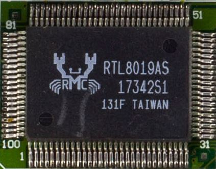
For the LAN controller, we have the Realtek RTL8019 which is a full duplex Ethernet controller that was released around 2001 1995 so it can only go up to 10Mbps. Running with a 20MHz crystal.
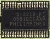
We have 2x Silicon Labs SI3210 telephone interface chips for our 2 analog phones. These interface chips are a global solution with a DC-DC controller than can output up to -94.5V for the phones (inductor or transformer options) with programmable line feed parameters/audio processing and ringing up to 90Vpk to name a few. This board went with the inductor option and when powered up was outputting -48V and -55V at the 100uF 100V capacitors.
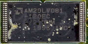
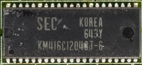
For the flash chip we have an Atmel 8Mbit AM29LV081 and a Samsung KM416C1204 16Mbit DRAM.
Troubleshooting Booting issues
When powered on, this unit would only show a red LED for the power light and a blue LED for Phone 2 and stay like that, like it’s locked up. Every now when power cycled, these lights would come on and then the system would shine these LEDs brighter, then power them off and work normally (only showing blue LEDs). Swapped out the 5V power adapter but that made no difference, it was drawing about 250mA when it wasn’t working properly.
So when it did power up properly, I measured the LDOs and the voltage going to all the chips except the LAN controller, all seemed to be fine. Went back to when it wasn’t working and found that the Si3210 chip wasn’t getting hot, measured the reset line which read 0.75V when not working and 2.05V when it was, odd. I traced it back to the LS32 OR gate which it was one of the outputs and the inputs were tried together and went to the main chip so that’s where I need to look.
On the main chip I checked the reset line and it seemed to be at 2.5V and tried to reset it but it just locked up like before (but I actually checked the wrong pin, I was checking the core voltage, more on checking the reset pin again later).
What I eventually found was that the 5V rail when unplugged sat at 0.4V and slowly started discharging. I plugged in the power, unplugged it, quickly shorted out the 470uF capacitor for a second, plugged in the power again and then it worked fine. Repeated this a few times and it woudl power up each time fine, so something about the 5V rail. Tried swapping the capacitor, no change. Removed the capacitor and it seemed better but if you unplugged and re-plugged in within a few seconds the issue would occur, you would have to wait 5 or more seconds and it would be fine, so it’s not really much of a solution.
I started looking at the flash chip, if the main chip boots, it would have to load the configuration from the flash, so I put the probe to one of the flash address pins to see. When working, there was constant interactions going on but when not working it didn’t do anything.
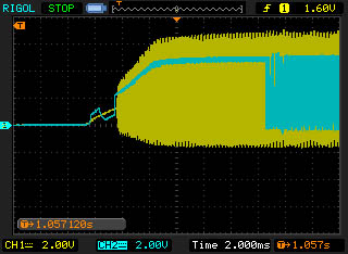
Then I looked at the CE pin (blue) with the crystal pin (yellow) to see when the main chip started and found that when starting well, it increased the CE pin slowly and then would start pulsing it.
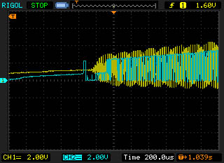
However when it didn’t start well, the CE pin was pulsed when the main chip was just starting off, the voltage levels are pretty low so it probably wouldn’t read anything back properly so something is definitely wrong, perhaps the chip isn’t waiting long enough for the clock to startup and it’s just executing instructions before it really should.

Checked the 2.5V and 3.3V regulators to see when they started up (Flash and SRAM use 3.3V) but they started at almost the same time. Compared the CE pin against the 2.5V/3.3V too.
I went back to re-checking the main chip’s reset pin, counted the pins and found the right reset pin this time, it was sitting at 5V. Touched it to ground when it wasn’t working and lo and behold it works! Repeated the test and it’s working fine. This reset line is also connected to the Flash chip too.
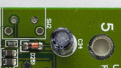
I was able to trace the reset pin which lead me to the back ports, there is a un-populated place for SW2, so it sounds like they had planned to add a reset button to it, they have a 10K resistor and a 10uF capacitor to create a slowly rising voltage which could be the cause of the issues or it’s just the ESS chip, either way, keeping the reset low for a little bit after power up and then putting it high solves the problem. Time to remove the resistor and capacitor for our own reset solution.
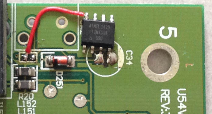
This sort of scenario would be suited for a supervisor chip (usually 3 pin) which you can buy that has a fixed delay, specific voltage threshold and open drain output, they are about 20-30c each but I don’t have any so it’s over to the ATtiny13A to solve this, all I’m doing is delaying for 500ms, outputting high on one of the pins which connects to the reset line and going to sleep forever. Tested a few times and it works perfect, solved!


Clever fix!
>Realtek RTL8019 which is a full duplex Ethernet controller that was released around in 2001
RTL8019 was _the_ NE2000 compatible chip in probably 95% of ISA ethernet cards ever made globally. It was designed ~1995. You only need this chip, 20MHz quartz, transformer, I2C eprom and ~10 passives for a fully working ISA card.
There was also PCI version designated RTL8029.
Nice, thanks for the info and correction!
Hi Alex,
Could you please list some more common voltage supervisor?
Hi Hiep,
There are quite a few available, like the MCP111T, MCP100T, TCM809, etc. You can find one with the right amount of delay time once the voltage passes the specific voltage you are looking for. The higher cost ones have adjustable voltages.
Thanks Alex for the quick reply on the part number.
BTW, I think I shorted the board by accident and nothing turns up now. Do you know by chance if there is a fuse that went on the board?
Damn, no fuses that I could see. Any burnt smell coming from the board? Your best bet would be to measure all the power rails to check which one isn’t right. Also try powering it with a different power adapter, as perhaps the fuse blew on that.
You could also measure the input side, near Q5, C119 just to see if the input voltage is present and where it isn’t, a rare case could be a trace got burnt/cut.