At work, we use Snom phones and we take quite a number of calls every day, when you use the handset and need to type it’s a bit difficult. There are some headset/headphones options available, the Snom uses 4P4C / RJ9/RJ10 connectors but I’ve always got my iPhone headphones on, so I’d like be able to use them on the Snom phone.
(sneak peak)
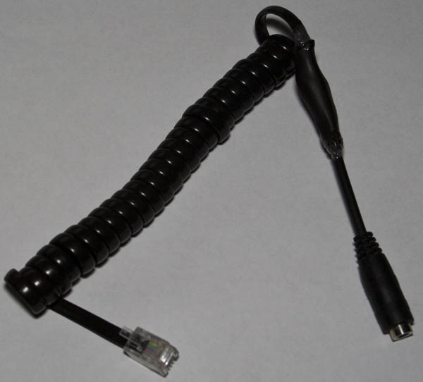
The first step was to build a Snom 4P4C to TRRS cable, I used a 220 ohm resistor for protection to find the left/right speakers and then used a 1.5K resistor for the microphone.
It turns out that the microphone was a little hard to hear so after removing the 1.5K resistor it sounded better but it wasn’t loud enough unless you place the mic close to your mouth.
After speaking with a colleague, the idea came about of being able to switch between an iPhone and the work desk phone easily, it shouldn’t be a problem since we can an analog switch to do this. I had the Ti SN74LVC1G3157 SPDT switch on hand and it should do the trick, just hook up 3 of these for the mic and speakers.
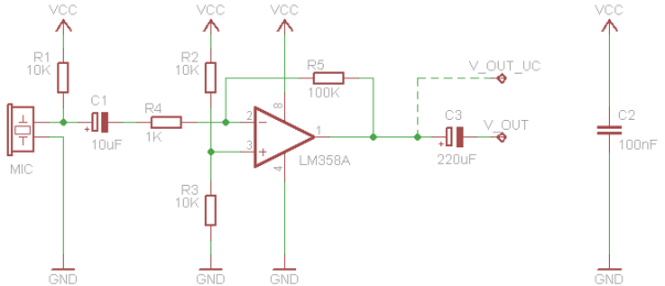
Now it’s back to making a boost circuit for the microphone, I looked around for a low cost op-amp and found the LMV358 which is just like the LM358 and it’s rail to rail. I found an LM358 op-amp inverting circuit which we’ll use to start off with (shown above). I firstly tried a non-inverting opamp configuration but it didn’t turn out to be as good as the inverting one above. The configuration above boosts the microphone’s output (which is AC coupled) by 100x and the 10K/10K divider on the non-inverting side keeps the opamp’s output at half of VCC so that when sounds are produced there will be an AC waveform (e.g with VCC/2 being 2.5V, we could get a waveform that goes 1.5V to 3.5V) just before the 220uF capacitor.
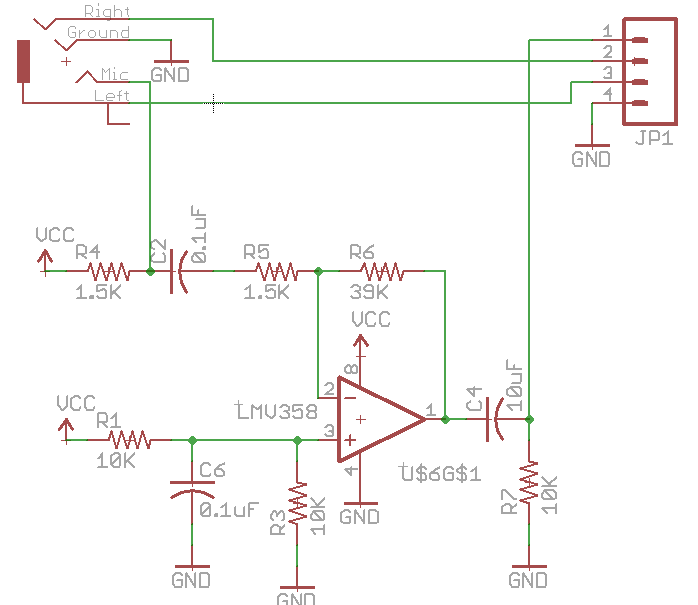
After doing a bit of researching and testing, I’m using a 1.5K resistor for the iPhone microphone which is what I’ve heard that’s what the iPhone uses to power it. I changed the 10uF capacitor to a 0.1uF to give a quicker response when powered up and reduced the boost to 26x for testing. The first thing to do was to test the microphone on the iPhone speakers (connected to the op-amp output before the 10uF cap) and it worked fine. Next was to connect it up to my iPhone (without the 10K pull down) but it just didn’t sound right, I found that adding a 10K load resistor to ground solved the issue.
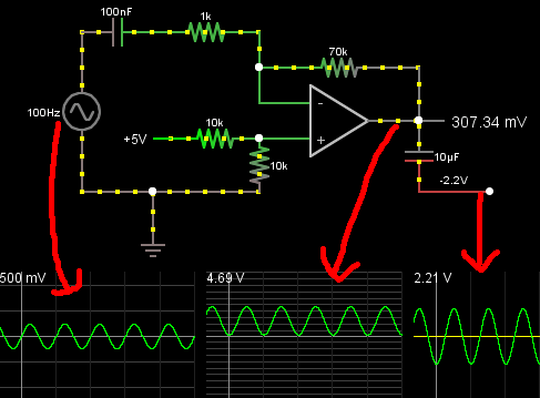
I was trying picture of how it would look like from the iPhone’s side and how exactly everything was fitting together so I’ve simulated it – pretend we’ve got a 500mV AC signal (mic signals are much lower than this), you can see the resulting waveforms, once it’s AC coupled it gives us the waveform on the right but that’s not exactly correct because the capacitor should really just pass through the signal as there is no load resistor.
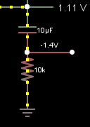
Once the load resistor of 10K is add, the waveform is now correct, after a little while the capacitor will have too much charge to change it’s voltage instantly which means it stays at relatively 2.5V and that results in the resistor taking the voltage drop when the opamps output changes. If the opamps output is 1.11V, the capacitor still has a charge of 2.5V which means the resistor has to be dropping -1.4V (1.1V – 2.5V) and that allows us to get the negative output swing we need, now it will appear on the iPhone like a microphone.
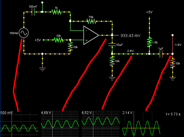
Now we simulate what the iPhone might have (assuming 1.5K with 1uF and 10K load resistor), we can see that the waveform is also carried in to the iPhone input too, so it’s good to go.
When the circuit is powered by a 3V coin cell it only takes about 0.5mA so it could last at least a few days but it would be better if it was powered by USB. I powered everything directly from the USB but it was too loud so I hooked up an LP2950 3V LDO regulator and it was better but there was a lot of noise. I thought that I’d build a PCB and perhaps that would remove some of the noise because at this stage it was all on the breadboard and moving the USB cable over the circuit introduced noise.
After building the PCB, I’ve got the option of using a coin cell or the USB however when using the USB I still had the same issue, the noise was reduced a little bit compared to the breadboard but it was still there. Download Audio_Mic_Boost_v1
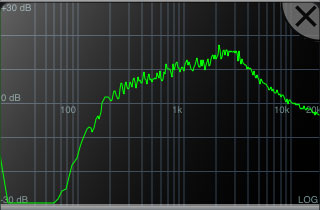
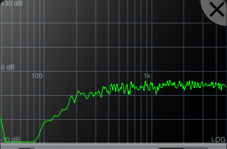
Using a program on the iPhone called N-track Tuner revealed the issue – we’re getting a spike around the 2-3KHz mark. I tried all sorts of things, RC filters, LC filters, DC-DC isolators, ferrite beads all before the LDO with no success.
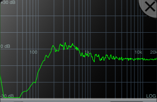
After posting on the EEVblog forum, I was given the advice to try the RC filter on the mic input which did help reduce the noise and after adding a larger 470uF capacitor to the LDO’s output it was nearly all gone.
Eventually I tried sticking an 220 ohm / 47uF RC filter after the LDO and just like that all the noise was gone, I wouldn’t have expected that the LDO would be generating the noise. I no longer need a large capacitor on the output or the RC filter on the mic input. Next I tried to plug in my iPhone to the front USB of the PC and the noise increased again, so I tried one of the back ports and it’s better. I used a USB cable that has a built in ferrite bead and now all the noise is gone, so it could just be the USB cable I was originally using wasn’t the best.
When testing the iPhone’s volume control buttons, they emit a waveform when pressed which appears not to pass properly when going through the opamp but when going through the analog switch it’s fine, so we’ll only have the boost take effect on the work desk phone.
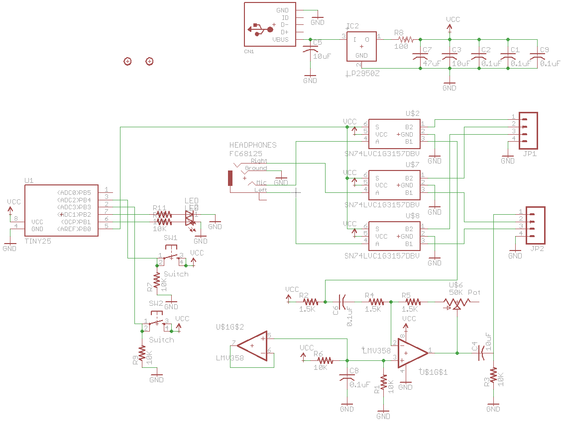
Now it’s time to build it all together, I was thinking of using an ATtiny with rotary encoder to control a digital pot change the gain on the opamp but that’s overkill, it’s easier just to use a 50K potentiometer to control the gain, there is also a 1.5K resistor in series with the pot (so our lowest gain is always 1x) as it’s possible for it to be close to 0 ohms. If you max the volume out (to 50K ohms), you encounter some distortion on the output if you speak too loud. Download Audio_Switcher_with_Mic_Boost_v1
The ATtiny just controls the the analog switches, buttons pushes and LEDs. Upon searching for TRRS cables, the proper ones are hard to find, there are a lot on Ebay but most have the mic shorted to ground or don’t have mic connected at all, I did find one were I could use the male TRRS connector (but the female connector couldn’t be used) so I’ve had to buy some TRRS connectors locally ($2 each, pricey).
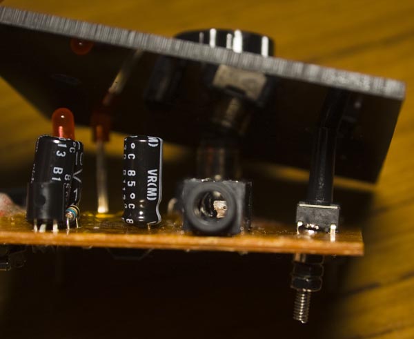
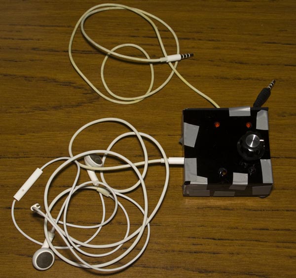
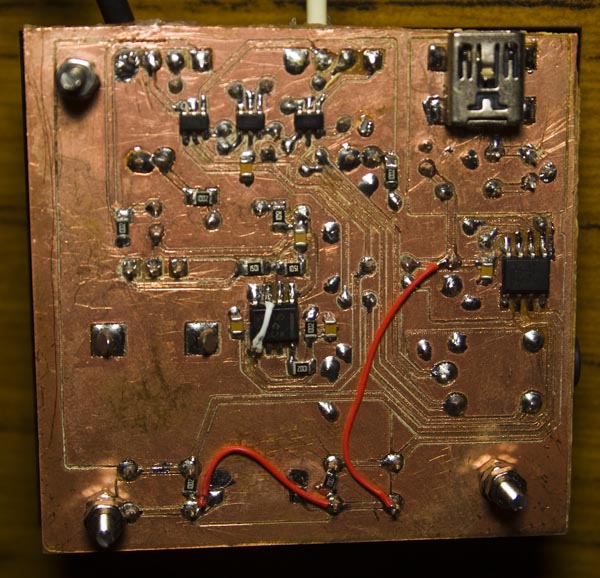
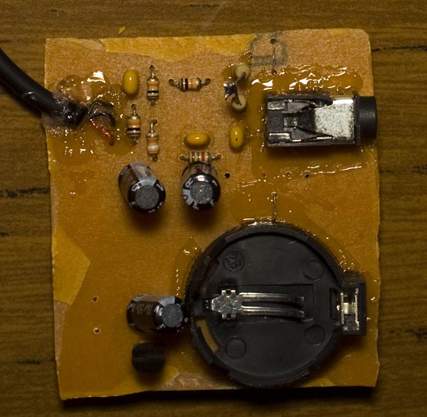
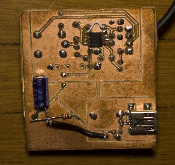
As you saw in the start, we’ve now got the PCB built. We have the 3 analog switches up the top, the opamp near the middle and ATtiny on the right. I built a quick mock up case (which will be redone soon) that has a female TRRS connector on the left, the white cable connects to the iPhone and the black cable goes to the work phone, 2 LEDs and 2 buttons. Soldering the PCB took a while as I was testing each part separately but in the end it all worked out and works great. It was quite the learning experience for me because I’ve never really played around with audio much and I’m sure there are many other ways to do this.


