Previously I made a small solar power garden light with an RGB LED controlled by an ATtiny13 and I have been thinking about how I could create a different project from it. The ability to control these RGB LEDs via wireless on demand seemed like an interesting idea – potentially you could program a sequence and have them execute it to give you a small light show if you had enough of them.
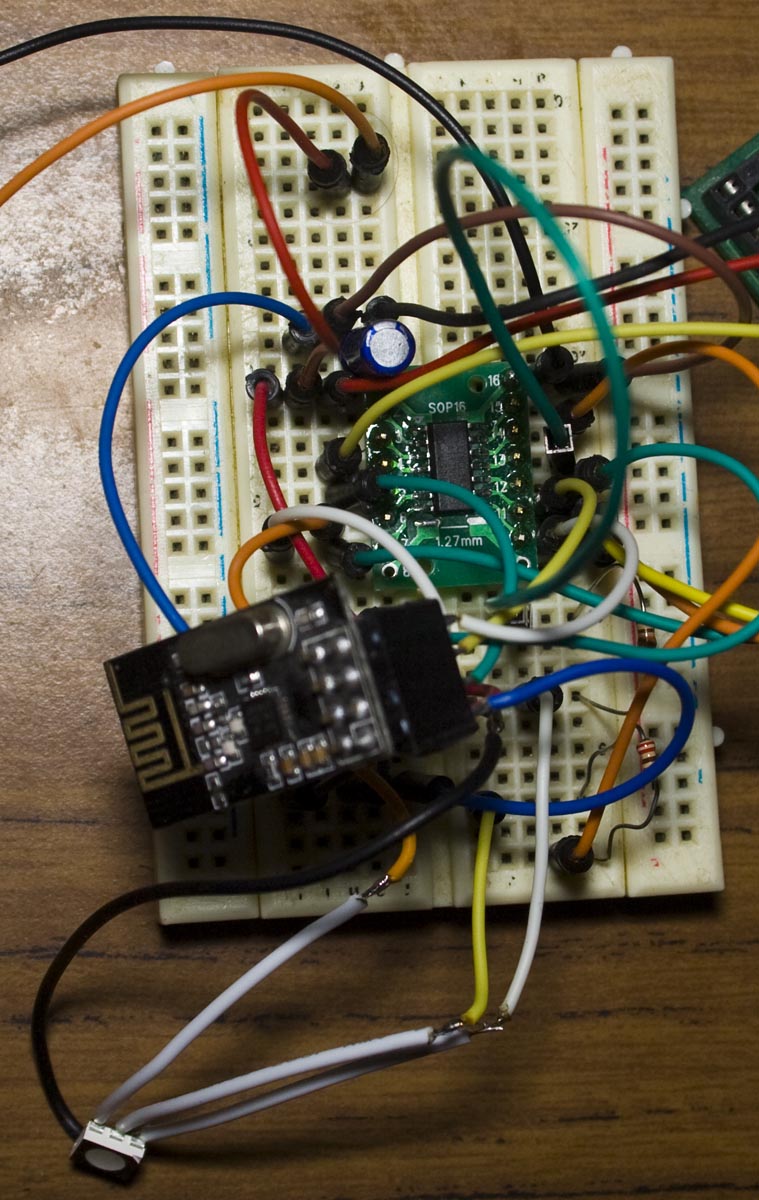
(sneak peak)
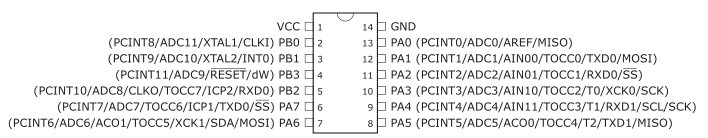
After browsing for an AVR, I found the ATtiny841 that has 3 timers which is exactly what I need to control each LED properly with PWM (another solution would be to use a WS2812 LED).
Each ATtiny841 was $1.3 so you can’t really go wrong, I didn’t know these MCUs were available so it’s a good idea to regularly browse supplier’s websites for new products. For the server side, I’m thinking an ATmega with 16×2 LCD and keypad to enter the sequence.
Client side
The ATtiny841 gives us the ability of selectable output pins for the timers which you’ll need to configure to have any output from the timer at all plus you also need to enable the timer output enable of the pin too.
![]()
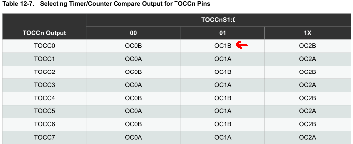
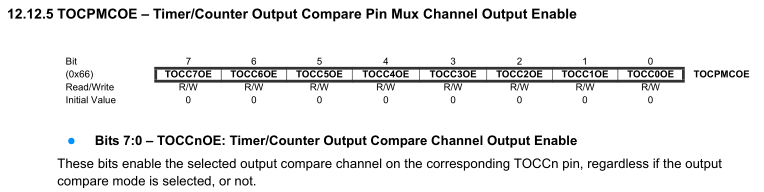
We’d like to keep using the SCK, MOSI and MOSI pins for the nRF (though with the 841 you can change these to an alternative pin), so we’re left with PA1, PA2 and PA3. For example, for Timer1 we use OCR1B and we will choose the output as TOCC0 (PA1) – we enable the TOCC0S0 bit so that it selects OC1B and then turn on the output enable bit TOCC0OE to activate TOCC0. It’s a little tricky to understand at first; you can always use Atmel Studio to simulate it if need be.
I’m using the Fast PWM with on inverting mode as it will give us proper zero brightness if we select it (255); using non-inverting mode and setting it to 0 still gives a small amount of light. Since I’m only running at 1MHz for the moment, I’m using no prescaler for the LEDs so we shouldn’t see any LED refreshing issues, we should run a bit faster so we could process nRF packets more quickly.
POWERDOWN;
watchdog_sleep(T1S);

// Check if server is sending packets
if (mirf_receive_data()) {
	awakeCounter = 30;
	setup_watchdog(T1S);
}
// Stay awake waiting for packets for 30 seconds
while (awakeCounter > 0) {
	if (mirf_listen()) { // Listen for new data
		awakeCounter = 30; // Reset 30 second counter

		redPWM = data_in[RED_DATA];
		greenPWM = data_in[GREEN_DATA];
		bluePWM = data_in[BLUE_DATA];
	}
}
mirf_CE_lo; // Stop listening
redPWM = 255; // Turn off LEDs
greenPWM = 255;
bluePWM = 255;
...

ISR(WDT_vect) {
	if (awakeCounter > 0) {
		WDTCSR |= _BV(WDIE); // Keep enabling watchdog until counter runs out
		awakeCounter--;
	}
	else {
		turnOffwatchdog(); // Turn off as no more packets received
	}
}
Now that we have the PWM done, it’s time for the code, ideally this will be running from a Lipoly battery so we’ll have it wake up every second, listen for any packets and if we hear something we’ll stay awake for 30 seconds otherwise we turn off the LEDs.
Since we have no other timers to use, I’m using the watchdog counter but we need to be very careful as to how we continue turning it back on/off otherwise there seems to be a potential it can cause the AVR to stall – I’ve found that in the watchdog interrupt itself, re-enabling the WDT/turning it off seems to work best in this particular case.
Server Side – LCD
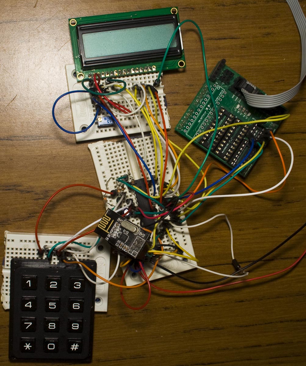
We’ll move onto the server side, firstly we’ll get the LCD running; instead of coding this ourselves I found that there’s already a HD44780 Library available, we’ll stick with using 4 bit mode with no RW line.
lcd_clrscr();
while (waitInput == true) {
	lcd_goto(0x00);
	display_headings();
	lcd_goto(0x40);
	for (int x = startDisplay; x < endDisplay; x++) {
		if (x == 0) {
			number_to_lcd_aligned(sequenceCounter);
		}
		...
	}
}
We display the headings and the corresponding numbers on the next line (0x40) whilst we wait for some input. The text shown on the LCD would be:
-N- A R G B Fd Bk Tm
0 1 0 255 0 0 1 500
The sequence / format is as follows:
- Sequence number
- To address (255 means every client)
- Red, Green, Blue colours
- Fade – 1 means fade to high and 2 means fade to low
- Blink – number of times to blink
- Delay time (16 bit) – how long to delay either when fading, blinking or when setting a colour
Keypad
I’ve got a 16 key (4×4) keypad which will be our input, the first 4 pins are the rows and the last 3 are the columns, by pulsing the columns high we can read the rows to determine which button was pressed.
// Keypad columns
DDRD |= (1<<PD4) | (1<<PD5) | (1<<PD6);
PORTD |= (1<<PD4) | (1<<PD5) | (1<<PD6);

// Pin interrupts
PCMSK2 = (1<<PCINT16) | (1<<PCINT17) | (1<<PCINT18) | (1<<PCINT19);
sbi(PCICR, PCIE2);
We’ll assign each pin to the ATmega, set the columns high by default and set a pin interrupt to all the rows so if any button is pressed an interrupt will be triggered.
// Keypad interrupt
ISR(PCINT2_vect) {
	PORTD &= ~((1<<KEYPAD_C2) | (1<<KEYPAD_C3)); // Turn off columns 2 and 3
	_delay_us(50); // Wait a little for other columns to drop to 0V

	// Test first column
	if (PIND & (1<<KEYPAD_R1)) {
		pushedButton = 1;
	}
	else if (PIND & (1<<KEYPAD_R2)) {
		pushedButton = 4;
	}
	else if (PIND & (1<<KEYPAD_R3)) {
		pushedButton = 7;
	}
	else if (PIND & (1<<KEYPAD_R4)) {
		pushedButton = 10;
	}
Once triggered, we turn off the second and third columns, wait 50uS because otherwise we receive incorrect results from the keypad and then start testing all the rows in the first column (1, 4, 7, *), we then do this for the other columns too.
else if (buttonFunction == 4) { // For sequence number, only allow up or down to be used
	if (pushedButton == 2 && sequenceCounter < 19) {
		sequenceCounter++;
	}
	else if (pushedButton == 5 && sequenceCounter > 0) {
		sequenceCounter--;
	}
	else if (pushedButton == 11) {
		buttonFunction = 3;
		selectedOption++;

		// Clear input
		inputCounter = 0;
		for (int a = 0; a <= 4; a++) {
			input[a] = 0;
		}
	}
	if (pushedButton == 0) { // Execute the sequence
		waitInput = false;
	}
After we find out which button was pressed, we can then process it based on a number of button functions I’ve made, for instance, the one above will let us scroll up or down the sequence numbers and execute the sequence if we press the 0 key.
// Start timer so that we don't repeat a character when the button is pressed
if (pushedButton != -1) {
	TCNT0 = 0; // Reset to 0
	TCCR0B = ((1<<CS01) | (1<<CS00)); // 64 prescaler
	sbi(TIMSK0, TOIE0); // Enable overflow interrupt
}
...
// Reset after ~16ms
ISR(TIMER0_OVF_vect) {
	pushedButton = -1;
	TCCR0B = 0;
}
I’ve added a timer every 16ms to clear the keypad’s pushed button variable otherwise the interrupt would trigger multiple times per key press.
Sequence execution
// Wake up all LEDs
data_out[FROM] = MYADDR;
data_out[TO] = ALLADDR;
data_out[RED_DATA] = 255;
data_out[GREEN_DATA] = 255;
data_out[BLUE_DATA] = 255;
for (int a = 0; a < 200; a++) {
	mirf_transmit_data();
	_delay_ms(5);
}
Once we’ve entered all of our input, we begin the execution of the sequence, firstly we wake up all the clients by sending packets which say to turn off all the LEDs for a second.
int optionTimeCombined = (int) (sequence[x][OPTION_TIME_HI] << 8) | sequence[x][OPTION_TIME_LO];

// Check blink first
if (sequence[x][OPTION_BLINK] > 0) {
	float delayCounter = (float) optionTimeCombined / 100 / 0.008; // LED delay - half on and half off
	for (int z = 0; z < sequence[x][OPTION_BLINK]; z++) {
		// Turn on
		data_out[FROM] = MYADDR;
		data_out[TO] = sequence[x][OPTION_ADDRESS];
		...
		data_out[BLUE_DATA] = 255 - sequence[x][OPTION_BLUE];
		mirf_transmit_data();

		// Delay
		for (int a = 0; a < 100; a++) {
			_delay_loop_2(delayCounter);
		}

		// Turn off
		...
		data_out[BLUE_DATA] = 255;
		mirf_transmit_data();

		// Delay
		...
	}
}
We check to see if the blink variable has been set, if so, we divide the delay time by 100 (to get a small number as 16bit is the maximum supported by the delay function) and then divide by 0.008 because the _delay_loop_2 procedure takes 4us each time it’s called so we double that which in turn reduces the delay time by 2 – so the LED will turn on for the delay time and also turn off for the delay time too. In the delay loop, we run it 100 times as we divided by 100 before to get a small number.
else if (sequence[x][OPTION_FADE] == 1 || sequence[x][OPTION_FADE] == 2) { // Fade in/out
	float delayCounter = (float) 255 / optionTimeCombined;
	float fadeCounter = 0;
	for (int z = 0; z < optionTimeCombined; z++) {
		data_out[FROM] = MYADDR;
		data_out[TO] = sequence[x][OPTION_ADDRESS];

		if (sequence[x][OPTION_FADE] == 1) {
			if (sequence[x][OPTION_RED] != 0) {
				data_out[RED_DATA] = 255 - fadeCounter;
			}
			...
		}
		else {
			if (sequence[x][OPTION_RED] != 255) {
				data_out[RED_DATA] = fadeCounter;
			}
			...
		}
		mirf_transmit_data();

		// Delay
		fadeCounter += delayCounter;
		_delay_loop_2(delayCounter/0.004);
	}
}
If blink wasn’t set, we check if fade is 1 or 2 and then we divide the 255 bits resolution that the LED has (we always assume the LED will either end up at it’s brightest or off) by the delay time to give us the increments we need to add to the brightness each time in the loop.
else if (optionTimeCombined >= 1) { // Wait this delay after setting LED
	data_out[FROM] = MYADDR;
	data_out[TO] = sequence[x][OPTION_ADDRESS];
	...
	data_out[BLUE_DATA] = 255 - sequence[x][OPTION_BLUE];
	mirf_transmit_data();

	// Delay
	float delayCounter = (float) optionTimeCombined / 100 / 0.004;
	for (int a = 0; a < 100; a++) {
		_delay_loop_2(delayCounter);
	}
}
If only the delay time was set, we just set the colour and wait for the delay time.
Download RGB_Wifi_Controlled_LED_v1.0
And that’s all there is to it, granted with this code you can only ever run 1 LED at a time (i.e, you can’t have 2 LEDs fade at the same time), however we could just modify the code to have the sequences stored on the clients themselves, the server programs each client one at a time and then sends an execute command to all of them. This would mean that the wireless communication would also be cut down, delay times will be more accurate and it would probably make more sense to use your computer to design the sequence and push it out on demand.


