From our previous post, the cases/mounts were built, a few more smaller changes were made and we added in the SMS capability. I thought that was the last change I would do to the alarm system for a long time but it turns out that the range of the remotes using the nRF24L01+ wasn’t very good, when outside the house you had to be within a few metres. This time we’ll be looking at adding 433MHz wireless to our system for the remotes to improve our range.
https://www.youtube.com/watch?v=mlmMsxs-U5Y
(sneak peak)
When I found the remotes range wasn’t great, I tried switching to 250Kbps operation of the nRF however I found that firstly there was an issue with the PCB antenna, sometimes it would work fine but other times I had to touch the antenna and then it works.
I added in a extra bit of wire to the antenna and that sorted it out though the range didn’t really improve much and by that time I had already switched the door/PIR sensors to 250Kbps too so I was stuck with it. So I needed a solution – could I possibly re-wire the old alarm system remotes to transmit the data I want?
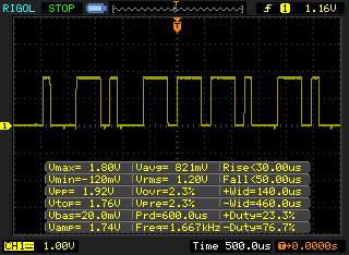
Luckily I had a 433MHz receiver and transmitter on hand so I could inspect the current remotes data that it transmitted and try to replicate it for myself. I was seeing a 120-138us high pulse for 0 bit and 400-440us pulse for 1 bit with a rise/fall time of about 4us. They were transmitting 24 bits where as I need to transmit 168 bits (160 bit for SHA hash and 8 bits for alarm system command).
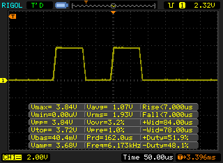
I wanted to see how fast it could really go and managed to push it up to 6KHz but there was a some gitter and this was with the transmitter close to the receiver so I’ll stick to something a bit lower.
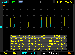
I started work on the receiver end, we need to detect the change between high and low then count long it’s been high for to determine if it’s a 0 or 1, I had some code pulse a pin high once it detected the end of the bit (blue line). The 433MHz wireless modules work best if you are constantly changing between a high and low signal otherwise if you leave it low for more than a couple of ms it will eventually stop transmitting.
433MHz Receiver Code
uint8_t blanking = 0;
while (blanking <= 50) {
	if (!(PINB & (1<<RF_IN))) {
		blanking++;
	}
	else {
		blanking = 0;
	}
	_delay_us(5);
}
// Wait for first high transition
while (!(PINB & (1<<RF_IN)));
We could use existing libraries however I’d like to try my own as it seems like it should be fairly straight forward enough. Firstly we listen for a blanking period for about 400us , this means the transmitter is sending a low signal. If we receive a high signal we reset the blanking counter and once we see the blanking period we wait for the first high signal transition.
// Read data
for (int x = 0; x < 21; x++) {
	uint8_t bitCounter = 0;
	uint8_t checksum = 0;
	while (bitCounter < 9) {
		// Wait for high transition
		uint8_t timeCounter = 0;
		while (!(PINB & (1<<RF_IN))) {
			_delay_us(1);
			timeCounter++;
			if (timeCounter >= 100) {
				return 0;
			}
		}
We have 21 bytes of data to read in, so we read 9 bits at a time – 8 bits and 1 checksum bit, I added the checksum bit so we can easily tell if we have real data or a random signal. We wait for the high transition, if it’s been longer than 400us at a low signal (it should only ever be ~200uS max – transmitter side) then we abort.
// Start timer to check how long it's high for
timeCounter = 0;
for (timeCounter = 0; timeCounter <= 66; timeCounter++) {
	_delay_us(1);
	if (!(PINB & (1<<RF_IN))) { // Break when it goes low
		break;
	}
}
if (timeCounter >= 66) { // High for too long, exit
	return 0;
}
Once we reach the high signal, we start a timer to see how long it’s high for, if it’s more than ~600us then we exit.
// Process counter
if (bitCounter < 8) {
	if (timeCounter >= 10 && timeCounter <= 35) { // 0 bit
		checksum ^= 0;
	}
	else if (timeCounter >= 36 && timeCounter <= 65) { // 1 bit
		data_in[x] |= (1<<bitCounter);
		checksum ^= 1;
	}
}
else { // Check the checksum
	if (timeCounter >= 10 && timeCounter <= 35 && checksum != 0) {
		return 0;
	}
	...
}
bitCounter++;
Now we process the timeCounter variable and process a 0 or 1 bit and add to the checksum. I outputted the timeCounter when testing to check how long each bit should be and added some variance. Once it’s time to check the checksum, we exit if the checksum doesn’t match what we expect.
// Verify SHA1 (160 bit) to the client's SHA1
uint8_t codeCounter = 1;
uint8_t remoteControlNumber = 1;
while (codeCounter < 30) {
	higher_rolling_code_check(codeCounter, remoteControlNumber);
	if (memcmp(data_in, random_number_sha, 20) == 0) {
		if (remoteControlNumber == 1) {
			// Copy random number that worked to current random number
			for (uint8_t x = 0; x < 32; x++) {
				random_number_r1[x] = random_number_check[x];
			}

			// Increment the rolling code addition to tell remotes which random number to use
			random_number_r1_addition = random_number_r1_addition + codeCounter;

			// Update on EEPROM
			...

			// Update R1Set
			if (R1Set == BLANK_EEPROM_BYTE) {
				eeprom_write_byte((uint8_t*) R1_SET_LOCATION, 0);
				R1Set = 0;
			}
		}
		else {
			...
		}

		// Process action
		if (remote_control_state == SYSTEM_ON) {
			...
		}
		...
		break;
	}
	codeCounter++;

	// Switch to other remote to test
	if (codeCounter >= 29 && remoteControlNumber == 1) {
		remoteControlNumber = 2;
		codeCounter = 1;
	}
After processing the signal, we check the SHA hash against the own hash we’ve generated and also check for higher hashes because the remote could be pressed a few times outside of the receivers range so I’m checking for 30 codes above the last one received. We save the last valid rolling code addition to the EEPROM and load from the EEPROM on boot up. Since I have 2 remotes, we switch to check the other remote after the 30 tries of the first one.
uint32_t codeCounter = 1;
// Init rolling code to 0
if (updateRC == 1) {
	rc_code_init(random_number_r1, random_number_r1_base, 0);
}
else {
	rc_code_init(random_number_r2, random_number_r2_base, 0);
}
higher_rolling_code_check(codeCounter, updateRC);

// Loop until we find the random number in use, press the button again to exit
while (memcmp(data_in, random_number_sha, 20) != 0) {
	codeCounter++;
	higher_rolling_code_check(codeCounter, updateRC);

	// Break if button pressed
	if (PINB & (1<<UPDATE_RC1) || PINB & (1<<UPDATE_RC2)) {
		updateRC = 0;
		break;
	}
}
Also we can press a button on the server then press the button on the remote and it will sync up the remote to the server, this is useful in case the remote gets pressed too many times or we have to switch to a new ATtiny chip.
433MHz Trasmitter Code
The transmitter code is easier than the receiver, we can wait for a pin interrupt and transmit the SHA hash as long as the button is pressed.
#define RF_BIT1_DELAY 400
#define RF_BIT0_DELAY 200
#define RF_BLANK_DELAY 200

// Blanking period
rf_433_low;
_delay_ms(1);

// Copy in remote control state
data_out[20] = remote_control_state;

// Transmit data out
for (int x = 0; x < 21; x++) {
	uint8_t checksum = 0;
	for (uint8_t i = 0; i < 8; i++) {
		if (data_out[x] & (1<<i)) { // High bit
			rf_433_high;
			_delay_us(RF_BIT1_DELAY);
			rf_433_low;
			_delay_us(RF_BLANK_DELAY);
			checksum ^= 1;
		}
		else { // Low bit
			rf_433_high;
			_delay_us(RF_BIT0_DELAY);
			rf_433_low;
			_delay_us(RF_BLANK_DELAY);
			checksum ^= 0;
		}
	}
	// Transmit checksum
	...
}
rf_433_low;
We transmit our blanking period, loop the 21 bits then transmit high or low and then the checksum afterwards.
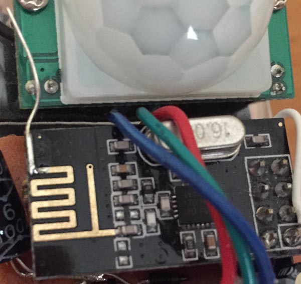
Modifying existing remotes and building the receiver
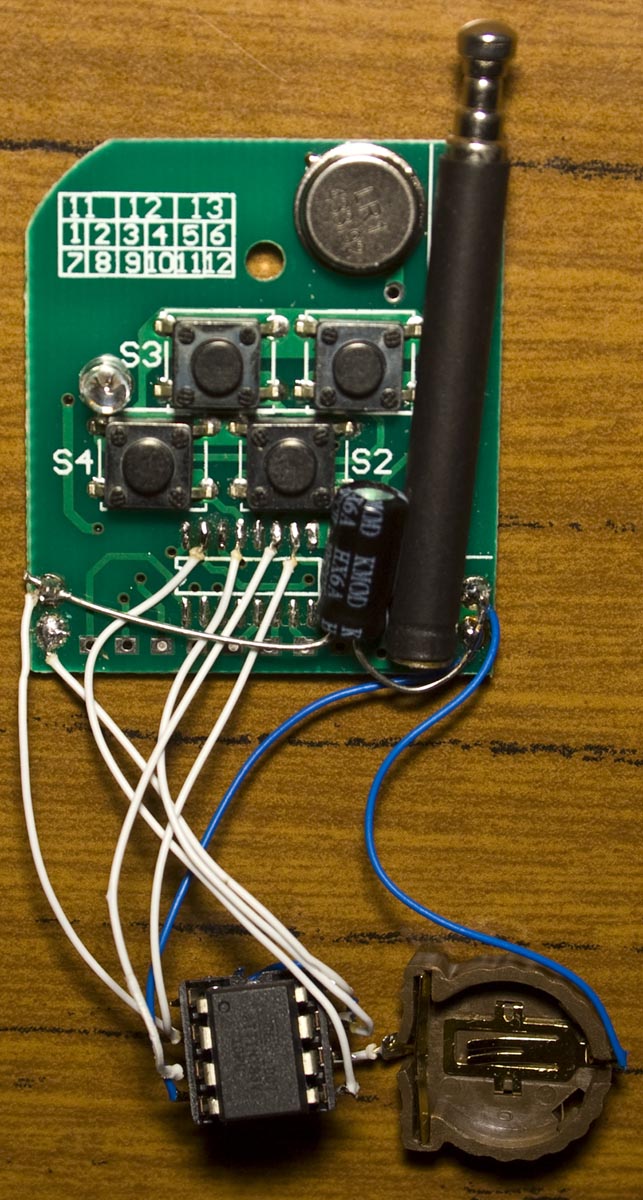
Now we can move onto modifying the existing remotes, we had a SC2260 chip in SMD in one remote and as DIP in the other one. After de-soldering it, I found that pin 15 was the RF transmitter pin and wired everything up. There used to be a small 12V battery but luckily a 3V CR1220 coin cell just fits and it also works when transmitting too, it draws about 3mA or so.
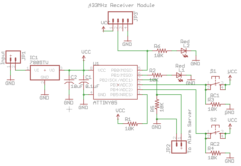
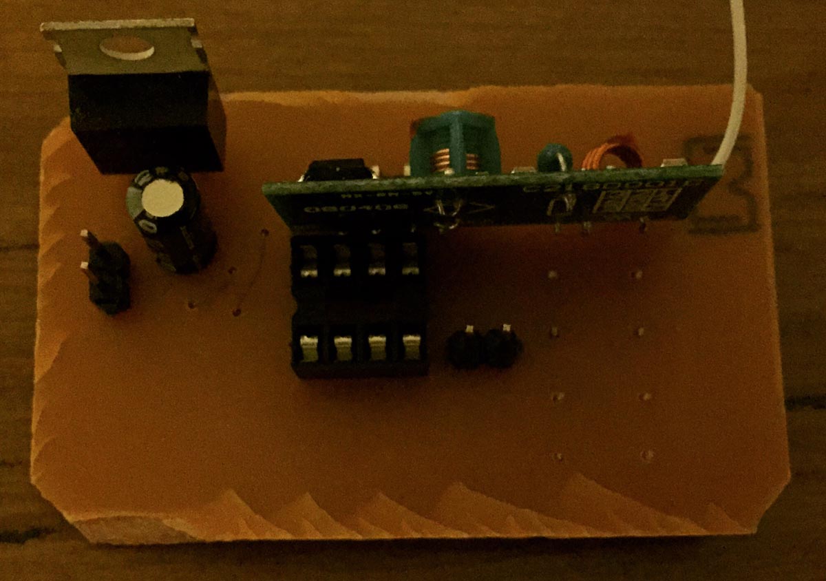
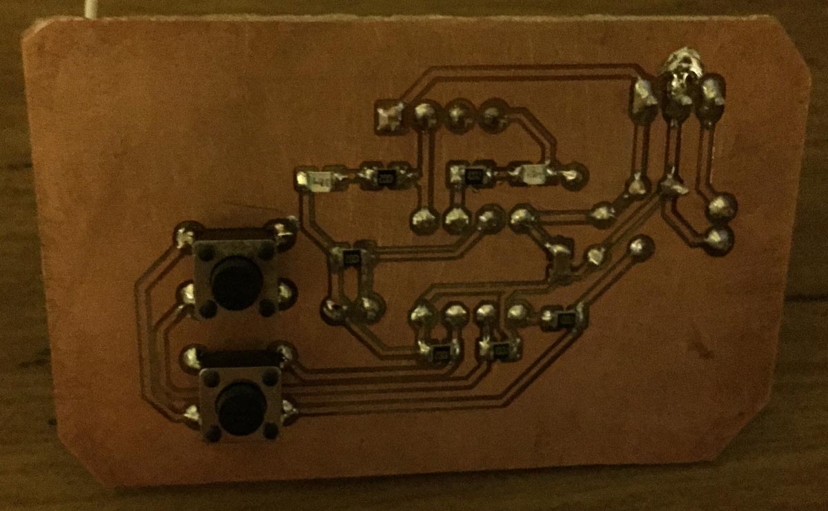
For the receiver I’m using the 433MHz receiver module with an LM7805 as it needs 5V to operate with 2 LEDs one for the modules input and the other when we receive valid data plus we have a output to the alarm system.
// Check for pin interrupt from 433MHz server
ISR(PCINT2_vect) {
	_delay_ms(250);

	// Check how long the signal is high for
	volatile uint8_t system_433mhz_counter = 0;
	while (PIND & (1<<SYSTEM_STATE_433MHZ)) {
		_delay_ms(10);
		system_433mhz_counter++;
	}

	// Process request
	...
}
On the alarm system server itself, we just have a pin interrupt that occurs and we wait until the pin goes low and process an action based on how long it was high for.
Download AlarmSM_Remote&Server_433MHz_v1.0
It works well and the range has now extended to the driveway so I should be able to switch it on or off once in the car like I used to do with the old alarm system.


