Posted in Arduino, Tinkering on Jan 6th, 2016
Lately my blog has been focused on quadcopters / RC cars and here’s another little one, I’ve been wanting to try out Acro mode but would rather not crash a whole lot to test it out. There’s a program called FPV Freerider which lets you simulate the quadcopter on a few different maps. Normally you would use a Flight Simulator Cable however I didn’t want to wait and they were out of stock locally.

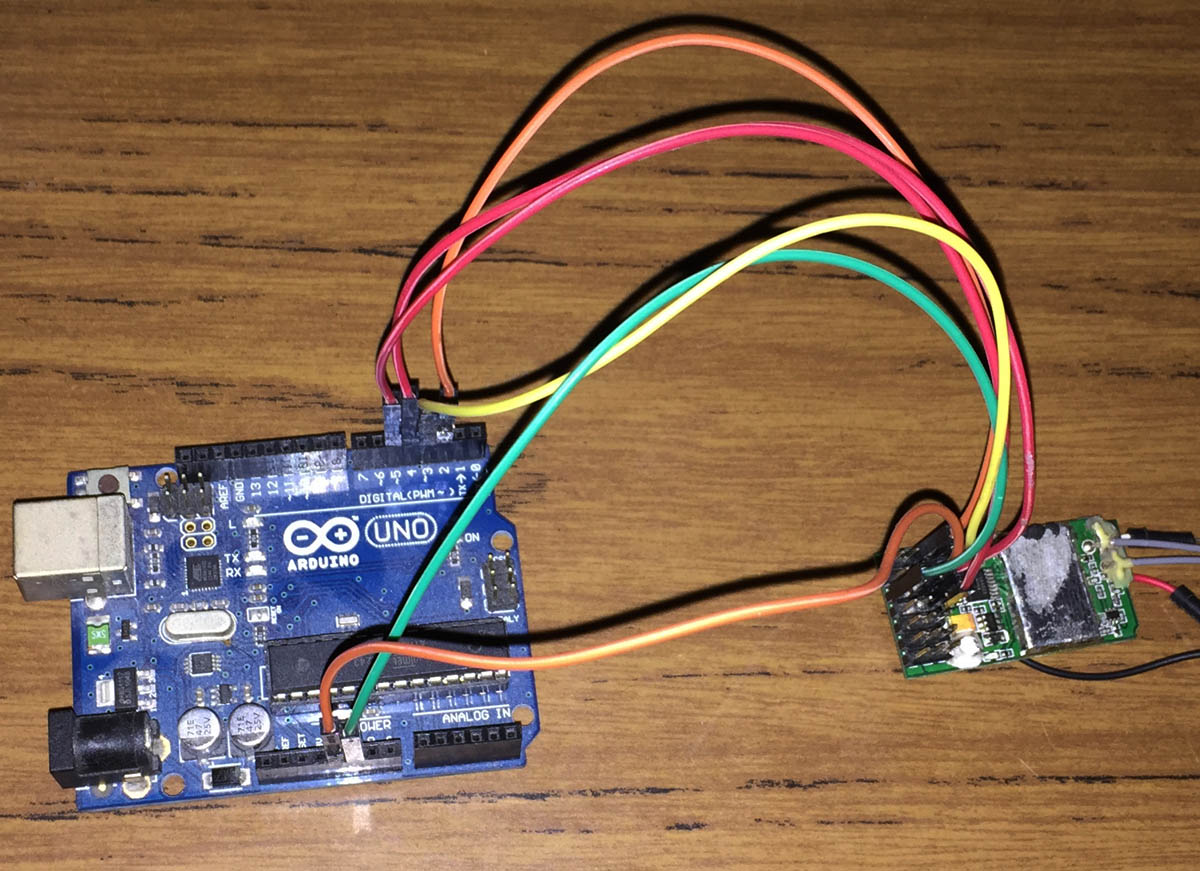
I happened to stumble upon Giuseppe’s Urso’s Blog which had some code for this exact purpose but for some reason only my first channel was working with my Turnigy iA6 receiver. The format being sent by 9600 baud serial was the FMS PIC 9600 which involves a special byte mixed in with the number of channels, another byte for buttons and then each channel has it’s own byte ranging from 0 to 255. Now that we have the format, I can write some code.
I found that my iA6 receiver outputs all it’s channels at the same time, i.e all at the same time and not one after another like some other receivers might, it actually makes it easier for us as all we need is an interrupt on any of the pins and then we start counting. Connect RX channel 1 to Arduino pin 2, RX channel 2 to Arduino pin 3 and so on.
#define RX_CHANNELS 4

volatile uint16_t ch1Result = 127;
...

void setup() {
  Serial.begin(9600);

  // Set inputs
  for (uint8_t x = 2; x < RX_CHANNELS + 2; x++) {
    pinMode(x,INPUT);
  }

  // Attach interrupt to pin 2 as rising
  attachInterrupt(0, time_channels, RISING);

  // Reuse Timer1 to count the microseconds after pin 2, etc go high
  TCCR1A = 0;
  TIMSK1 = 0;
  TIFR1 = 0;
  TCNT1 = 0;
  TCCR1B = (1<<CS10);
}
After playing around with the Arduino micros function, it had glitching every few results so I used the timers directly. We setup the pins as inputs, attach the interrupt INT0 to pin 2 to only trigger when the pin goes high and reset the timer to the default.
(more…)
Read Full Post »
Posted in Arduino, Projects on May 28th, 2015
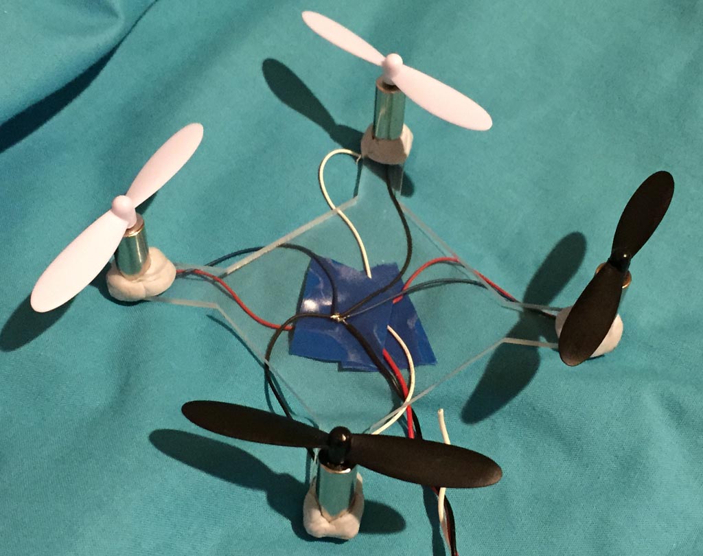
I recently got into the quadcopter hobby and purchased a UDI U818A mini quadcopter from Ebay which is fun to fly and have been experimenting changing the battery packs and adding FPV. I’ve been thinking about going to a larger quadcopter but before I do, I’d like to plan around with making my own micro quadcopter and experimenting with the software.
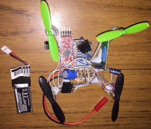
After purchasing 4 micro motors (Hubsan X4 H107), a set of propellers to suit, a MPU6050 3 axis accelerometer and gyro, I was ready to start building.
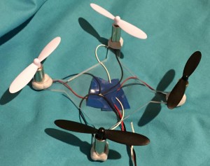
The first part was to build a frame, using my CNC I built one from acrylic just big enough to fit all 4 motors with propellers without touching each other, a bit of blu-tac later and they are semi-secured in place, good enough for testing. One big downside is that acrylic is heavy compared to most other materials.
Testing the 4 motors all at once at different voltages gave me the following current draw results – 1.7v @ 780ma, 2.5v @ 1.2A, 3v @ 1.5A, 3.5v @ 1.9A, 4v @ 2.2A but I expect that it could be double or triple that due to the wires I was using so each one might draw 1-1.5 amps each.

(more…)
Read Full Post »
Posted in Arduino, Projects on Jun 5th, 2013
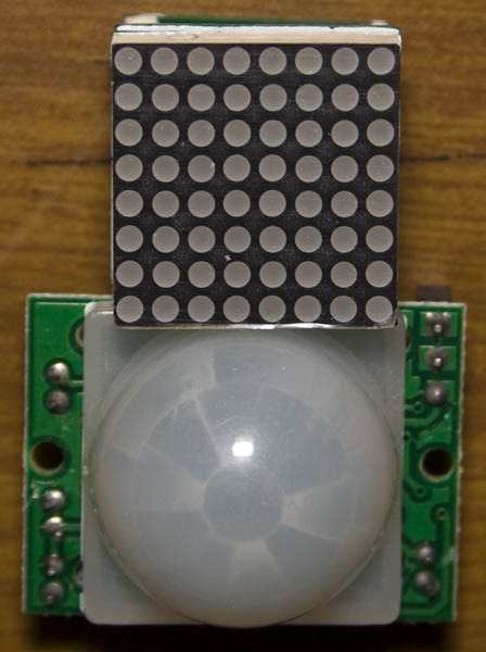
A downside of the AT Mini Matrix Ctrl is that if you have your animation only playing a few times an hour that you are very likely to miss it. You could have it running every minute for a specific time but it’s not that great if no one is there to see it.
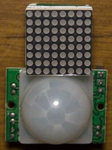
The solution to this is to use a PIR module (H8157 on Ebay) to detect if someone is around. The problem is that the PIR module is quite large compared to the led matrix so it would look out of place.
I started looking at IR transmitters/receivers and using them to reflect off a surface which would detect if someone was there however to have decent accuracy you really needed to use quite a bit of current which isn’t what I wanted. So back to square one, what can we do with the PIR module?
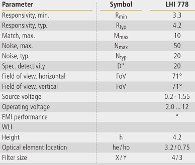
After researching the PIR sensors themselves, some datasheets (above is a random datasheet I found) said that they already had some noise reduction and some had application examples. The PIR sensors themselves can cost $2 or more even on Ebay which was odd as the PIR module was about $2 itself.
(more…)
Read Full Post »
Posted in Arduino on May 22nd, 2013
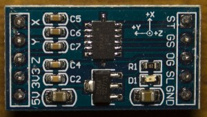
I’ve been meaning to play around with accelerometers and found the MMA7361 on Ebay for $3.
I checked if there was a MMA7361 library for the Arduino which there was so I tried it out but I kept receiving the same readings even if I disconnected the accelerometer from the Arduino – maybe I was doing something wrong. I briefly looked at the code and it seems they were doing a lot but the pin out of the MMA7361 made me believe it should be easy. Edit: I found there is a working example in Arduino > Sensors > ADXL3xx
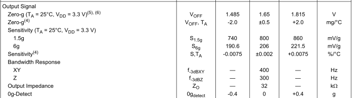
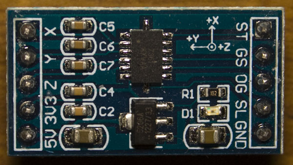
I looked up the datasheet and found it’s pretty straight forward if you just want to read the x, y, z axis, a simple ADC reading of each pin should be all that we need. There is a sleep pin (SL) which puts it to sleep which makes it only draw 3uA. Some other pins include the 0g pin which goes high when all axis’s are at 0g, a self test pin (ST) and a g select pin (GS) that allows you to choose 1.5g or 6g sensitivity.
With some other accelerometers I believe you can have it pull a pin high if it detects movement but the one I got it doesn’t have that functionality – it would be very useful for battery powered designs. One thing to note is that 0g is about half of the VCC. The Z axis is only half VCC when the board vertical.
(more…)
Read Full Post »
Posted in Arduino on Apr 13th, 2013
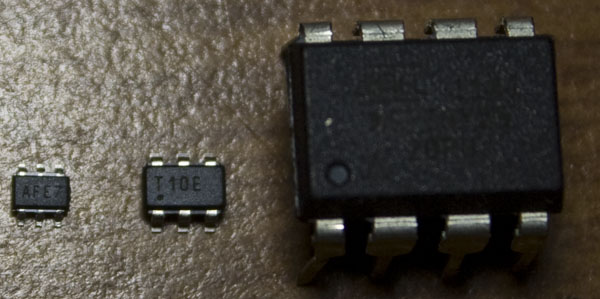
When I was placing an order for some parts I happened to find an I2C digital potentiometer (MCP4017T) on special at 4 cents each, so I bought some and now that I re-check the price they are 70 cents each.
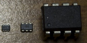
The package it comes in is a SC70-6 which is even smaller than the ATtiny10 (side by side comparison above, ATtiny85 on the right too).
Digital potentiometers can be useful if you want to change your resistance without tweaking your pot with a screwdriver, the example which I’ll be showing is adjusting the contrast on an 16×2 LCD module, it can make your project be more professional if you had it all inside a case. Another use could be an op-amp with an adjustable gain.
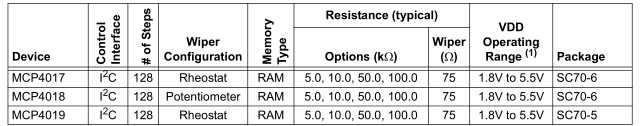
There are different pot options you can go with – 5K, 10K, 50K or 100K, I went with the 10K version. With a 10K pot, you can adjust it from 0 ohms to 10K ohms in this case in 128 steps of 75 ohms.
(more…)
Read Full Post »
Posted in Arduino, Projects on Mar 16th, 2013
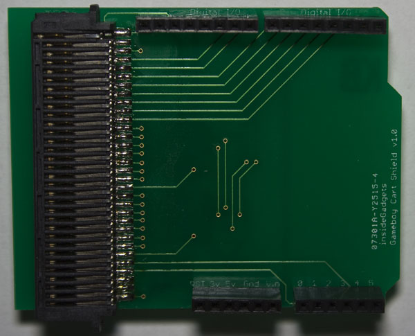
It’s been nearly 2 years since I last worked on my Gameboy Cartridge Reader (GBCartRead) and I never released a PCB but it has been something I’ve been meaning to do for a while which I can now check off my list.
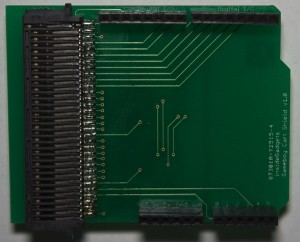
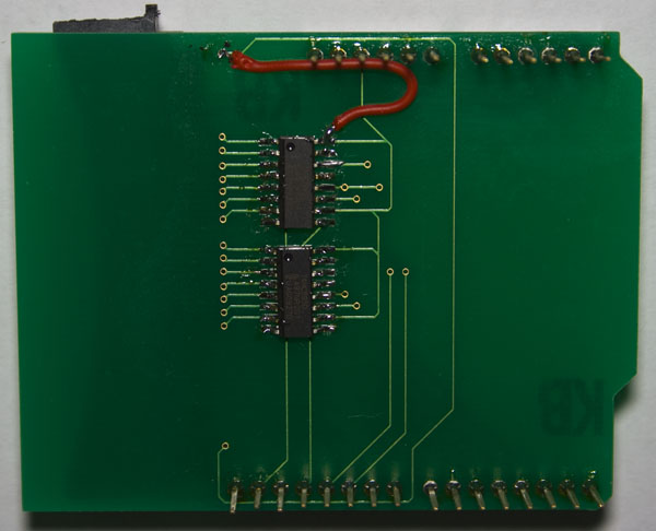
I received the PCBs for the Gameboy Cart Shield a few days ago, soldered all the components and noticed that somewhere along the lines I didn’t connect up the VCCs together so I have a bodge wire on the bottom of the board. Something I should have done was make the silkscreen text much larger than what it current is.
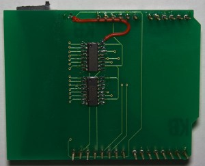
The Gameboy Cart Shield PCB is now available for sale.
Read Full Post »
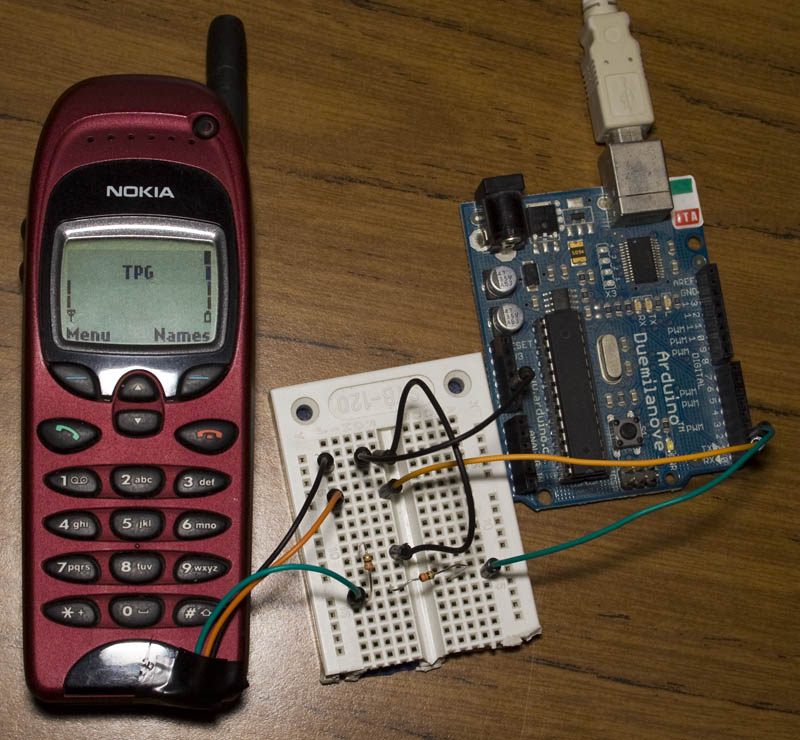
Posted in Arduino, Tinkering on Feb 10th, 2013
Following on from my post on How to use Nokia F-bus to send an SMS message where I used an Arduino to send an SMS message, at the end I mentioned moving to an ATtiny2313A/4313 so that we don’t need to use the Arduino.

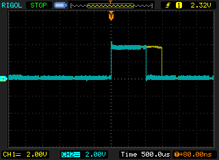
The ATtiny2313A/4313 features Universal Synchronous and Asynchronous serial Receiver and Transmitter (USART) with the features above. The Nokia F-bus uses 115,200 bps with 8 data bits, no parity bit and 1 stop bit.
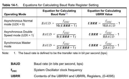
To use USART we need a clock input, there are 3 clock options – Asynchronous Normal, Asynchronous Double and Synchronous Master. For Asynchronous, the clock is generated from the system oscillator where as the Synchronous option is where we provide an external clock signal input. Using the UBRR register we can dial into the baud rate that we want but it depends on the system oscillators frequency.
(more…)
Read Full Post »
Posted in Arduino, Tinkering on Jan 12th, 2013
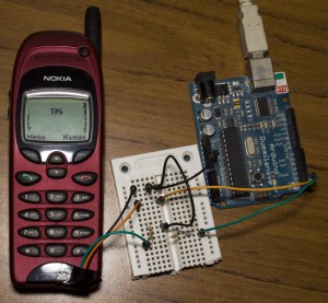
A few months ago I was looking into how to use Fbus with a Nokia phone but didn’t have much luck and instead just wired up the keypad. I decided to revisit Fbus and this time happened to find some AVR code which could send/receive SMS’s so now I’m able to send an SMS using the Arduino and I’ll explain how we do this.
Before I go any further the 3 resources I used were:
Embedtronics – F-bus packet explanation with some examples of a packet
Avr and nokia3310 interface(sms) project on AVRfreaks – Code for an AVR to send/receive SMS
Gnokii – F-bus documentation and code to run on a computer
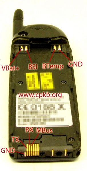
Firstly you need a Nokia phone which the F-bus commands are known, the best documentation is available for the Nokia 6110 and derivatives (Nokia 6130, 6150, 6190, 5110, 5130, 5150, 5190, 3210, 3310) – this was found in \gnokii-0.6.31\Docs\protocol\nk6110.txt
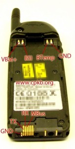
I was able to purchase a Nokia 6150 from Ebay for under $20. You can search up the Nokia pinout for your mobile phone – I found the TX, RX and GND for my phone.
(more…)
Read Full Post »
Posted in Arduino, Tinkering on Oct 15th, 2012
About a year ago I purchased an ATtiny10 with one of my orders but didn’t get to program it because I didn’t have a programmer and didn’t bother getting one. I was looking at Hackaday – it looks like someone wrote up with an ATtiny10 programmer using the Arduino! You program it by pasting the hex file into the serial window.


If you haven’t seen the ATtiny10 before it’s really small (above is a picture of it next to the ATtiny85) but has minimal features, program space, SRAM, registers and functions. It can run up to 12MHz, has 1KB space, 32bytes SRAM, no EEPROM and an 8-bit ADC.
The majority of users whom use the ATtiny10 seem to use assembly instead of C; some examples of ASM files can be seen on the link above. I wanted to use C on it, however WinAVR which uses avr-libc doesn’t support it so we’ll have to use AVR Studio.
(more…)
Read Full Post »
Posted in Arduino, Tinkering on Apr 30th, 2011
So the Arduino software has been easy to use but I’m thinking about using V-USB in one of my projects. V-USB is an implementation of the USB protocol that can run on an Atmel AVR microcontroller but in order to integrate it into one of my projects it’s time to move away from the Arduino software.

I’ll show you how we can create our own version of the ATtiny45/85 Blink without the Arduino software. We will use setup/timer functions from the internal Arduino wiring.c file because it’s easier to use something that works.
First thing we’ll do is download WinAVR from http://winavr.sourceforge.net. After installation, the default directory is C:\WinAVR-20100110.

But before we start with WinAVR we need a starting template, so what I did was download AVR Studio 5 Beta and start a new blank project. The reason I’m using Programmers Notepad instead of AVR Studio is that it’s a very simple interface and from my testing actually compresses things better when compiling.
(more…)
Read Full Post »