Following on from my post on How to use Nokia F-bus to send an SMS message where I used an Arduino to send an SMS message, at the end I mentioned moving to an ATtiny2313A/4313 so that we don’t need to use the Arduino.
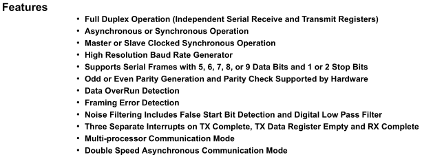
The ATtiny2313A/4313 features Universal Synchronous and Asynchronous serial Receiver and Transmitter (USART) with the features above. The Nokia F-bus uses 115,200 bps with 8 data bits, no parity bit and 1 stop bit.
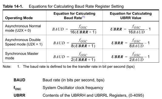
To use USART we need a clock input, there are 3 clock options – Asynchronous Normal, Asynchronous Double and Synchronous Master. For Asynchronous, the clock is generated from the system oscillator where as the Synchronous option is where we provide an external clock signal input. Using the UBRR register we can dial into the baud rate that we want but it depends on the system oscillators frequency.
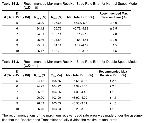
The recommended total error mismatch between the receiver and transmitters are listed above, these errors can come from the generated baud rate (using UBRR) or the system oscillator. For 8 bits, the error should not be more than 2% -/+ at normal rate or 1.5% -/+ at double rate. We know that the internal oscillator in the ATttiny can be 10% -/+ accurate so we won’t be using it.
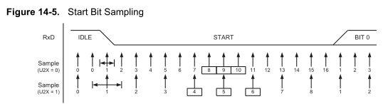
Just a bit of background – the difference between normal speed and double speed mode is the amount of times it samples the incoming serial data – either 16 times (normal speed U2X = 0) or 8 times (double speed U2X = 1).
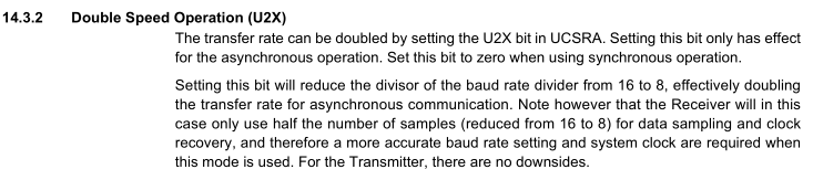
Since I’m just focused on transmitting I don’t need to worry about receiving and using double speed mode won’t affect the transmitter.
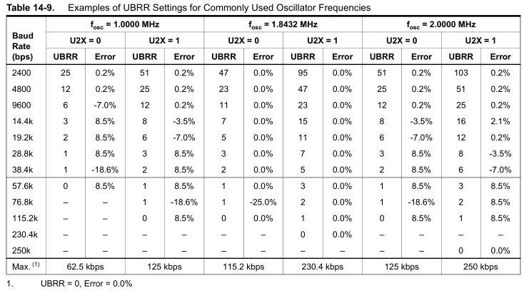
We have some examples of UBRR settings above with the normal and double rate modes. Using an oscillator of 1MHz (and assuming there is no error on the oscillator itself), it would do 115.2k but with an 8% error which isn’t acceptable as I mentioned before it needs to be 2% -/+ at normal rate or 1.5% -/+ at double rate. Using 1.8432MHz will indeed give us a 0% error rate however that’s an obscure crystal frequency which I don’t have.
Using the formula of Baud rate = crystal oscillator / 16 (UBRR + 1) for normal mode and Baud rate = crystal oscillator / 8 (UBRR + 1) double mode, we can go through common crystal frequencies until we find one that fits.
I found that 12MHz with a UBRR of 12 and at double rate works well: 12,000,000 / 8 x (12 + 1) = 115,384 bps which is very close to 115,200.
![]()
The error rate comes to ((115384 / 115200) – 1) x 100 = 0.159% which is great so now we can proceed with the schematic/code.
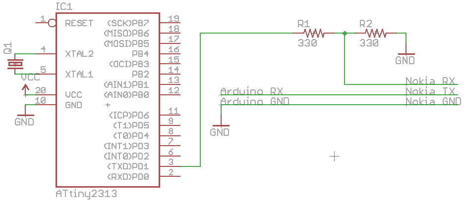
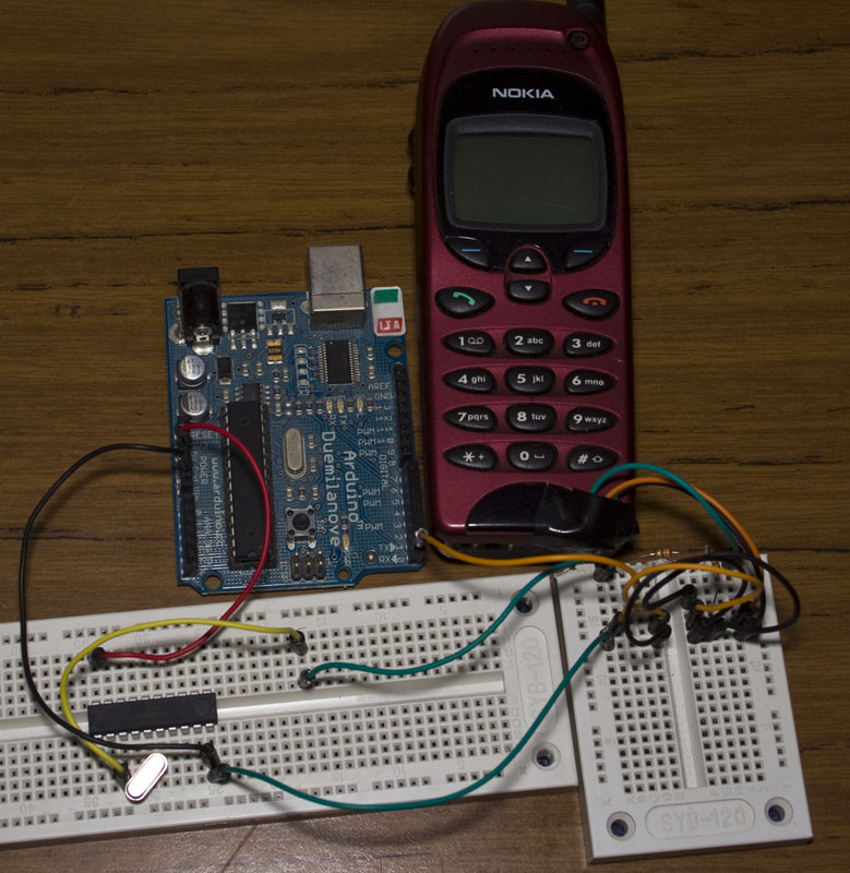
I just have the ATtiny2313 TX hooked up to the Nokia’s RX and the Nokia’s TX going to the Arduino’s RX so I can see the results.
void setup(void) {
  UBRRL = 12; // 115,200 Baud rate
  sbi(UCSRA, U2X); // Double rate
  sbi(UCSRB, TXEN); // Transmitter enable
  sei(); // Turn on interrupts
}
First we set up the baud rate UBRR (UBRRL is the low byte), set up double rate and enable the transmitter. If you were using something other than 8 bits, no parity, 1 bit stop (defaults) then that’s when you need to change the UCSRC register.
// Transmit USART data
void USART_Transmit(unsigned char data) {
  while ( !( UCSRA & (1<<UDRE)) ); // Wait for empty transmit buffer
  UDR = data;
}

while(1) {
  // Sleep until the Watchdog timer wakes us up
  watchdogSleep(T1S);

  // Transmit U 128 times
  int x;
  for (x = 0; x < 128; x++) {
    USART_Transmit('U');
  }

  // Send the test message
  for (int x = 0; x < (sizeof(msg) / sizeof(unsigned char)); x++) {
    USART_Transmit(msg[x]);
  }

  _delay_us(250); // Wait for USART transmit to complete
}

ISR(WDT_OVERFLOW_vect) { }
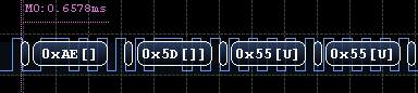
We firstly sleep for 1 second, transmit U 128 times to initialise the F-bus and then send our message which in this case is the Get HW&SW command. The USART_Transmit function was taken from the ATtiny2313 datasheet and basically once the UDR data buffer is empty, we transfer 1 byte into it. UDR is also a buffer in which we can receive serial data too.
The reason I use 250 microseconds delay is because I found that if you went to sleep straight away, the USART wouldn’t send the last 2 bytes properly. It would send 1 byte as 0 and then those 2 bytes would appear malformed at the start of the next transmission.
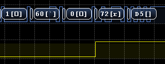
Instead of using the watchdog timer I used delay and it worked just fine. For a test, I set a pin high when I last wrote to UDR and as you can see it goes high 2 bytes behind when the USART really finishes. I tried to use the USART Transmit Complete bit however that only reduced it to 1 byte not sending / appearing in the front.
From the start of the start bit to the next start bit it’s 86uS, so I just delay 250uS and that fixed up all my issues; I guess you shouldn’t sleep right after you use the USART.
void setup() {
  Serial.begin(115200);
}
void loop() {
  while (Serial.available() > 0) {
    int incomingByte = Serial.read();
    Serial.print(incomingByte, HEX);
    Serial.print("");
  }
}
Now we want to hear if the phone says something back, for testing we’ll use the Arduino’s RX for this with the simple code above.
1E C 0 7F 0 2 D1 0 CF 71
1E C 0 D2 0 26 1 0 0 3 56 20 20 35 2E 30 32 A 30 32 2D 30 32 2D 39 39 A 4E 53 4D 2D 31 A 28 63 29 20 4E 4D 50 2E 0 1 46 3C A9
And we do receive our standard HW&SW information so it all works.
Download ATtiny2313_Serial which includes the sending the SMS function too.


Could you please help ?
How to activate a gsm module (which has Rx and Tx) with an imei number?