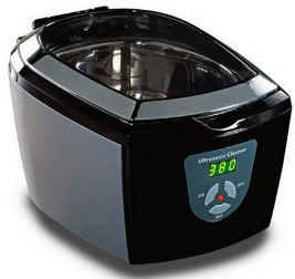
I was given a Visage Ultrasonic Cleaner to see if I could extend it’s timer settings from the maximum setting of 480 seconds to 960 seconds. An Ultrasonic Cleaner uses ultrasound to create small bubbles in the water and when those bubbles collapse it generates enough temperature and pressure to remove dirt and clean objects.
My first thought was that it would have a single board and that I would have to use an ATtiny to press the buttons in a sequence to turn it on for 480 seconds two times in a row. When I went to turn on the Ultrasonic Cleaner to make sure it was operational, it didn’t work. After shaking it a little bit, it seemed to turn on, so something is loose inside.
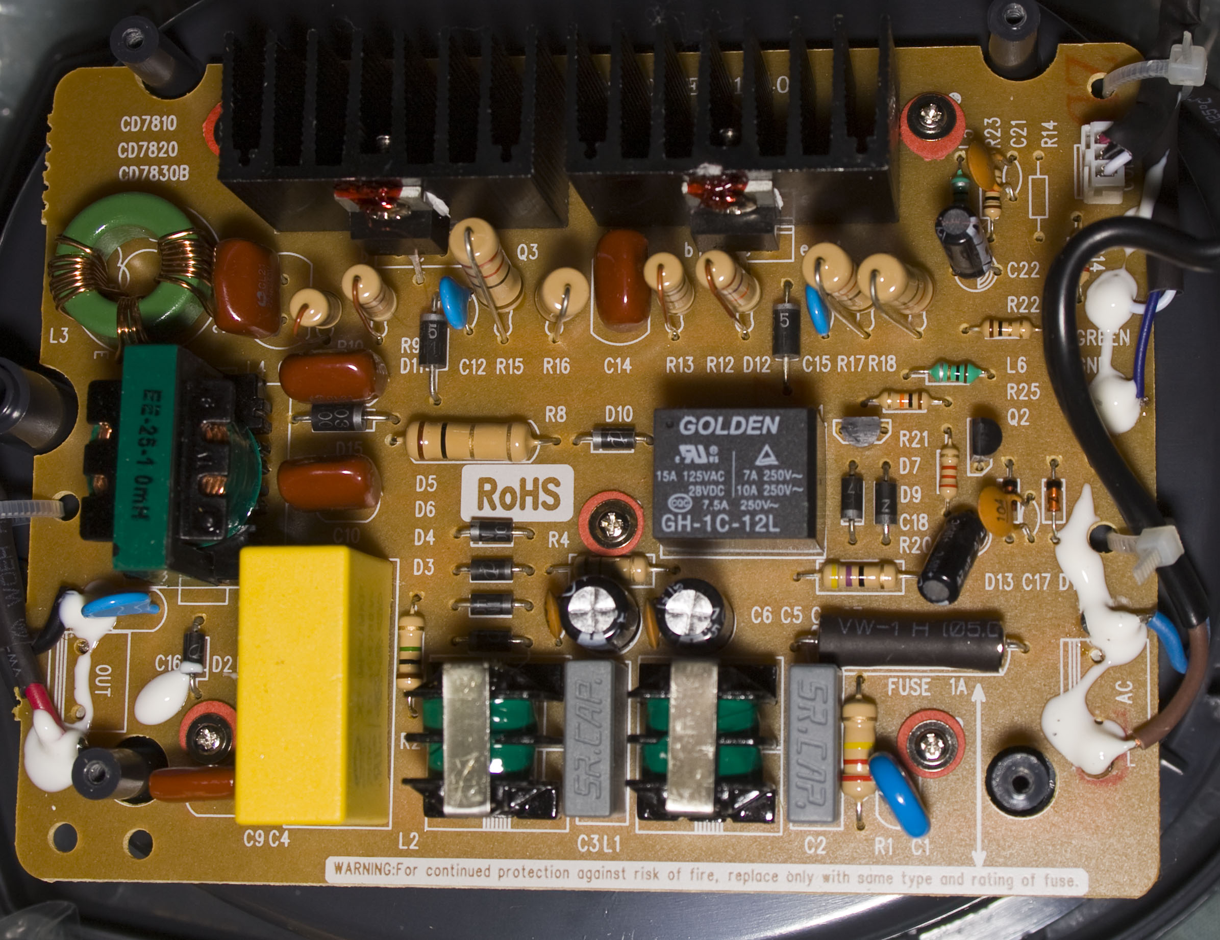
Upon opening it up, we have the single board but no MCU in sight. The components worth mentioning are the relay and 2 transistors (I assume they are due to the B / E marking) with heatsinks.
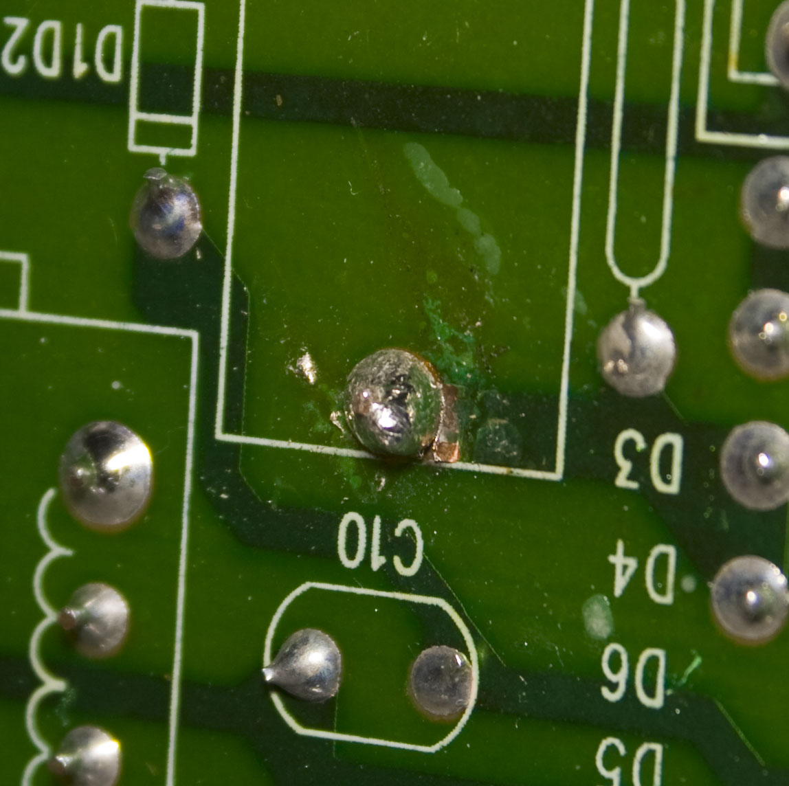
I found that one of the the large yellow capacitor leads were loose and had broken from the track. After re-soldering it, it all works well now.
On the front where the buttons/LEDs are located, there are only 3 wires going to it – Vcc, Ground and something else. After powering it up, Vcc reads as 4.7V and when the I turned on the cleaning function, the other wire read 4.3V.
Tracing the wire coming from it lead to the relay so things just got easier than I thought it would be and I don’t have to open up where the buttons/LED are contained – all it would be doing is switching the relay on and then off once the timer finished. When I shorted Vcc to the other wire, it turned on the cleaner and drew about 8mA (although the first time I tested it, it drew 38mA so my circuit is based on that figure).
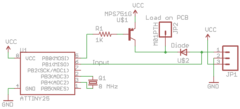
By an ATtiny25 with a PNP transistor and a 1K base resistor we can switch the load on or off. Because I don’t know what kind of circuitry is at the button/LEDs side we’ll protect those with a diode – for example, if they used an MCU to switch the load on and off, by default the pin would be low so if I switched the load on with my ATtiny, the current could flow through to it. The diode also allows us to detect whether the user turns on the cleaner via the buttons so it retains it’s original functionality. I’m using an 8 MHz crystal for the timer so it’s more accurate than the on board oscillator (just because I had one lying around).
volatile uint16_t counter = 0;
uint16_t count_limit = 29296; // 960 seconds

int main(void) {
  setup();
  while(1) {
    // Sleep for 10 seconds
    _delay_ms(10000);

    // Check if pin is high which means ultrasonic cleaner is already running
    if (PINB & (1<<sensePin)) {
      system_sleep(); // Sleep forever
    }
    else {
      PORTB &= ~(1<<relayPin); // Turn on PNP

      // Turn on timer
      TCCR0B |= ((1<<CS02) | (1<<CS00)); // 1024 prescaler
      TIMSK |= (1<<TOIE0); // Enable overflow interrupt

      // Wait until counter limit reached
      while (counter < count_limit) {
        _delay_ms(100);
      }

      // Turn off timer
      TCCR0B = 0;
      TIMSK &= ~(1<<TOIE0); // Disable overflow interrupt

      PORTB |= (1<<relayPin); // Turn off PNP
      system_sleep(); // Sleep forever
    }
  }
}

ISR(TIM0_OVF_vect) {
  counter++;
}
The code is very simple, we delay for 10 seconds and if the user hasn’t started the cleaner, we switch on the relay and use timer0 to count to 960 seconds at which point we’ll sleep forever until the user power cycles the ultrasonic cleaner. Download ATtiny25_Ultrasonic_Cleaner_Timer_Mod
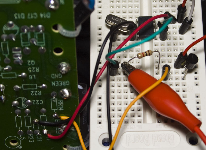
Testing the circuit, it all works as expected.
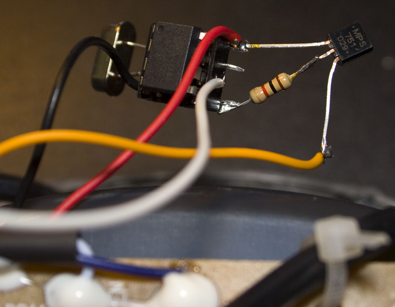
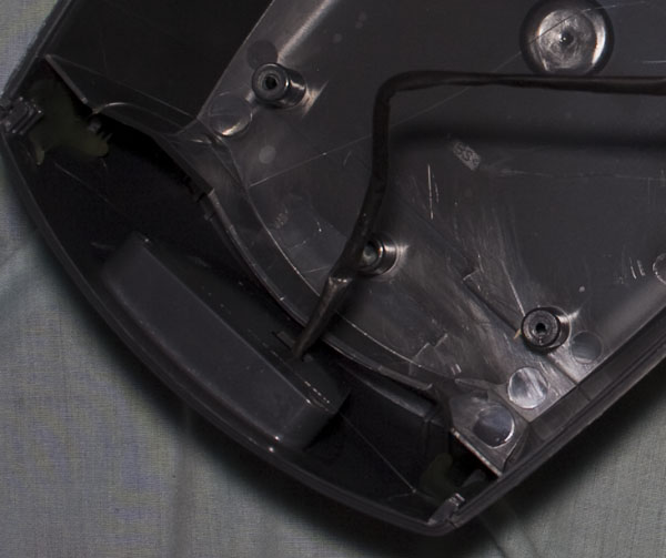
I soldered everything together – here’s how it looks. I duck taped that to the inside, gave it another test and works just fine.


