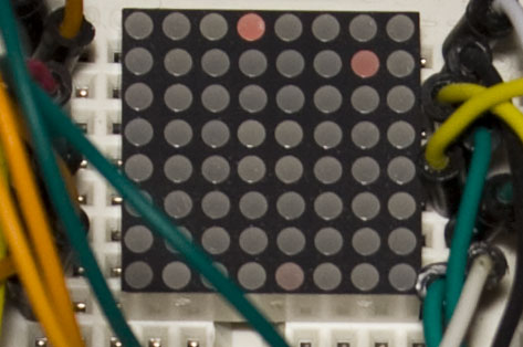
A while ago I picked up a small 20mm 8×8 LED matrix (LEDM88SMR) and have been thinking about making it battery powered to display some animations or text on specific dates such as on new years eve or on a birthday. I’m thinking of placing all the components on the underside of it so it will have more height but to not exceed the 20mmx20mm width/length.
The first thing is to build the circuit up with the Arduino using 2x 74HC595s and since I’ve worked with LED Matrix’s before, I already have some code I can reuse. Now that it works, I thought I would start designing the PCB (a bit later on it will be re-designed). Download 8x8_LED_Animation for the Arduino.
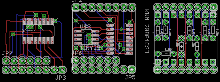
What I like to do first is lay out all the components and then draw in draft wires as place holders to make sure there won’t be any overlapping wires. I came up with 3 PCBs (left is bottom board, right is top board) which mount on each other using the Arduino style headers plus 1 more PCB for the battery. This design has an ATtiny25/45/85, 2 shift registers and 1.5K resistors.
4 PCBs did seem like quite a lot and I started looking for an single chip solution – I found the ATmega48A which comes in a 32pin TQFP package and it was pretty cheap (the ATmega168A was also around that same price point).
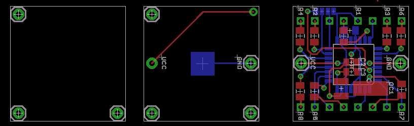
The new PCB design has 3 PCBs:
– The left PCB used to stablise it on a flat surface otherwise it would be on sitting on the battery. The connectors would be a male and female connector between the left and middle PCB so the boards can be removed and the battery fitted or removed.
– The middle PCB is where the battery is mounted which is on the bottom. As like on the AT25TTL, I couldn’t use a normal CR2032 battery holder as it would stick out so by taking out the pins in the battery holder we can reuse them to make a smaller sized holder.
– The right PCB is the ATmega48A mounted on the bottom with 8x 1.5K SMD resistors and the LED matrix mounted on top.
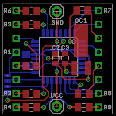
A closer look at the top PCB – I had a bit of room left and added in a small 32.768KHz watch crystal with 2 capacitors which would mean that I could potentially program the current date/time to the ATmega plus the date/time to trigger the LED matrix so you could leave the battery plugged in – I haven’t tested the timer in operation as yet.
I don’t expect it to be too accurate as it’s not laid out as best as possible (Best Practices for the PCB layout of oscillators) but if it’s off by a few minutes every month then that’s not much of a concern. I’ve added 4 SMD pins on the left so I can re-program the ATmega once it’s soldered in place.
// Redraw the 8x8 matrix by reading the data out of the sections array
void redrawMatrix(int sectionSelection) {
  for (int row = 0; row < 8; row++) {
    byte data = sections[sectionSelection][row];
    for (byte column = 0; column < 8; column++) {
      if (data & (1<<column)) {
        LEDs[row][7-column] = 1;
      }
      else {
         LEDs[row][7-column] = 0;
      }
    }
  }
}

// Light the LEDs by going through each row/column and wait a little while
void lightLED(void) {
  int x = 0;
  for (x = 0; x < 8; x++) {
    // All columns stay low (off) and rows that have a 1 go low (on)
    PORTB = ((1 ^ LEDs[x][2])<<PB3) | ((1 ^ LEDs[x][5])<<PB2) | ((1 ^ LEDs[x][7])<<PB0);
    PORTC = ((1 ^ LEDs[x][3])<<PC3) | ((1 ^ LEDs[x][1])<<PC2) | ((1 ^ LEDs[x][0])<<PC0);
    PORTD = ((1 ^ LEDs[x][4])<<PD5) | ((1 ^ LEDs[x][6])<<PD3);

    // Set the column to go high (on)
    if (x == 0) { PORTD |= (1<<PD4); }
    if (x == 1) { PORTC |= (1<<PC1); }
    if (x == 2) { PORTB |= (1<<PB5); }
    if (x == 3) { PORTD |= (1<<PD7); }
    if (x == 4) { PORTB |= (1<<PB4); }
    if (x == 5) { PORTD |= (1<<PD6); }
    if (x == 6) { PORTD |= (1<<PD2); }
    if (x == 7) { PORTD |= (1<<PD1); }

    _delay_ms(2); // Delay a bit so the LEDs light up for enough time
  }
}

while(1) {
  redrawMatrix(currentSection); // Redraw the new 8x8 matrix with the next animation

  // Looping through all the sections
  if (currentSection > 0) {
    currentSection--;
  }
  else {
    currentSection = 15;
  }

  // Light up the LEDs a few times to fill in time
  for (int i = 0; i < 10; i++) {
    lightLED();
  }
}
Above is the code which is going to be used on the ATmega. The redraw matrix function reads the section array and loads it into the 8×8 array. With the light led function we light up the LEDs column by column starting from the top. Download AT_Mini_LED_Matrix_v0.1.
We set the rows that have a 1 in the array to be 0 (Gnd, hence the 1 XOR the array reading) and then we set the column that x is to be high (Vcc). In the main loop we need to run the light led function a few times, the more times we run it the slower the animation displays – 10 seems to be a good number.
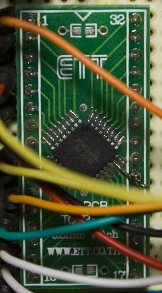
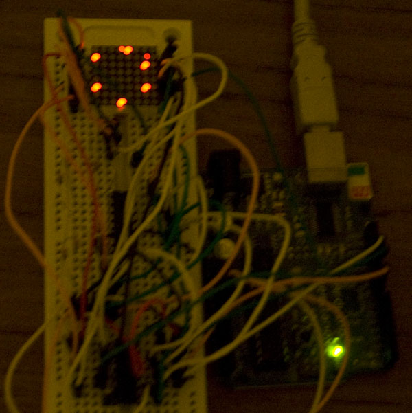
After waiting a few weeks for a 32pin TQFP to DIP adapter, I was ready to prototype the ATmega48A with the LED Matrix. I believe I overheated my first ATmega when trying to solder it to the PCB as I didn’t use flux and spent lots of time trying to remove solder bridges.
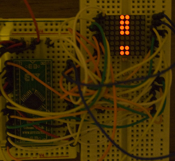
When I used flux for the next ATmega, it made soldering so much easier and it all works.
If you want to make your own animations, follow the steps found in this post but for step 1 – you draw it going bottom to top, step 2 – untick 0x option, step 3 – visit this LCD Down Reversed ASM to Array Converter page.
In the next part I’ll look into using the 32.768KHz crystal for the timer whilst still using the internal 1MHz clock, looking into how to keep track of the date/time (most likely using the unix timestamp) and changing the animations to be written to flash and read back using PGM.


