So the Standalone Temperature/Voltage Logger has worked out but I wanted to make a temperature logger more smaller and in doing so, switch back to the two board idea I originally used – one be the logger and the other be the reader.
It appears that most people who have bought the SATVL go with the 512Kbit EEPROM so we’ll provide that EEPROM as the only option and use 2 bytes per reading. In wanting to make everything smaller, it’s time for us to switch to SMD parts.
The most important part is which ATtiny MCU to go with. I was thinking of the ATtiny10, a very small chip but it only has an 8 bit ADC. The next MCU I thought of was the ATtiny13 but I found that the cost of it was more than an ATtiny25, so the ATtiny25 it is.
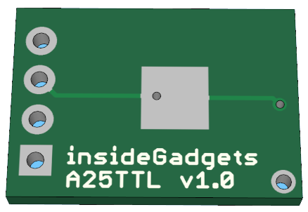
(sneak peek of PCB)
.
Logger Schematic
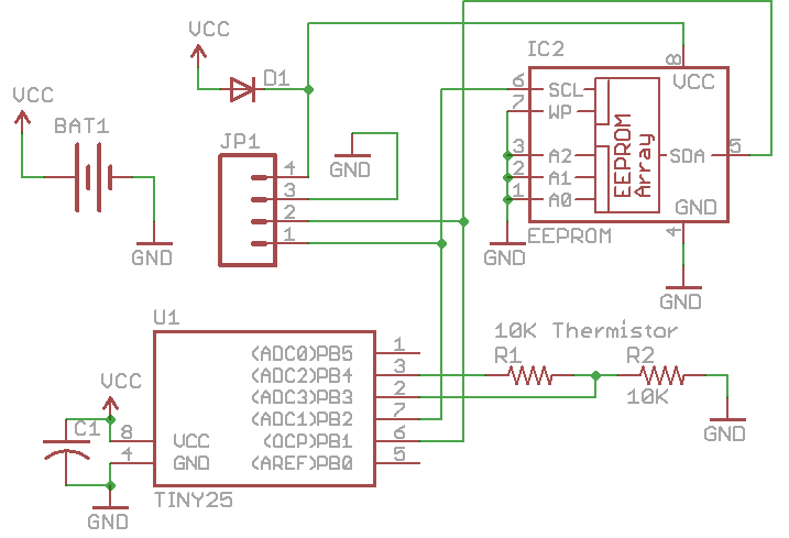
The logger board will be very simplistic, just a 10K thermistor, 10K resistor, 0.1uF capacitor, diode, battery and 4 pin header which breaks out VCC, GND, SDA and SCL. When we want to extract the data, we need to remove the battery and connect the 4 pin header to the reader which directly connects to the EEPROM. The reason the diode is there is so the ATtiny25 doesn’t power up and start re-logging.
Upon doing some quick testing, the ATtiny25 still powered up. I’ve heard that the MCU can power up if you feed voltage to one of it’s input pins which is what I was experiencing, so the diode can now be removed as it’s ineffective.
.
Reader Schematic
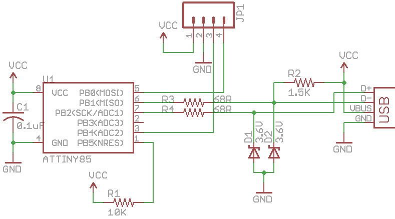
We just have our standard V-USB circuit for the reader.
.
EEPROM Troubleshooting
My new solution to detect whether the logger had be plugged into the reader was to set SCL/SDA high so the ATtiny25 could detect these and go to sleep forever.
This seemed to work well for the 64Kbit EEPROM I was testing with however when I moved to the M24512-WMN6P EEPROM SMD there was something odd going on. With the 64Kbit, the EEPROM pulled SCL/SDA to ground but the 512Kbit left them floating, so the ATtiny25 sometimes thought it was plugged into the logger when it wasn’t.
I ran the ADC on the floating pins and it didn’t go over a reading of 20 and I found it sometimes (though very rarely) drew 12mA when the pins were floating. The new solution is to check whether the pins are floating and if they are then start logging, if they aren’t then sleep forever.
// De-initialize SCL/SDA pins and set the bus low
void SoftI2cMasterDeInit(void) {
  PORTB &= ~(1<<TWI_SDA_PIN);
  DDRB &= ~(1<<TWI_SDA_PIN);
  PORTB &= ~(1<<TWI_SCL_PIN);
  // Don't re-set the clock to an input
}
I’ve modified the SoftI2cMasterDeInit function to not switch the clock back into an input as this seems to affect the M24512 EEPROM – that pin would float.
// Write 1 byte to the EEPROM
  bool soft_i2c_eeprom_write_byte(uint8_t deviceAddr, uint16_t writeAddress, byte writeByte) {
  ..
  // Delay 6ms for the write to complete. This value depends on the EEPROM you use so check your EEPROM's datasheet.
  _delay_ms(6);
  ...
}
And when writing to the EEPROM, the datasheet says it takes 5ms so to account for the 10% -/+ timer I’ve made it 6ms.
// Setup the ATtiny
  void setup(void) {
  ...
  // Check if we powered up from the USB port as TWI_SCL_PIN would be low for a second or two from the other ATtiny85 so we know not to start logging.
  // The ST M24512 EEPROM appears to leave the SCL and SDA pins 'floating' (note that this isn't always the case with other EEPROMs)
  // Read the ADC 10 times every 32ms which should give us enough time to find out if the SCL pin is floating
  for (int x = 0; x < 10; x++) {
    if (analogRead(analogSCLPin) <= 5) { // Not floating?
      system_sleep(); // Sleep forever
    }
    watchdogSleep(T32MS);
  }

  // Initialse I2C
  SoftI2cMasterInit();

  // Wait 8 seconds before logging to make sure the battery wasn't disconnected and re-connected when being removed or installed
  watchdogSleep(T8S);
}
As part of the setup, here is where we run the ADC 10 times to detect if we are plugged into the reader. If it isn’t plugged in, we wait 8 seconds before we start logging as the battery may be connecting/disconnecting when inserting/removing it.
.
Changing the Thermistor function
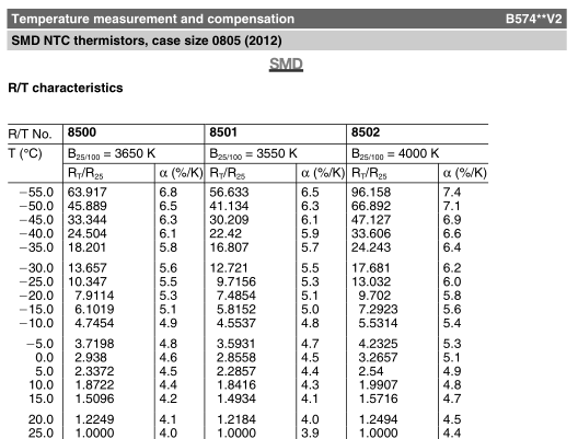
We have to change the thermistor function once again back to the one that the older versions of the SATVL used because the Epcos B57471V2 5% 0805 thermistor that I chose doesn’t have the 3 or 4 Steinhart-Hart Co-efficients in the datasheet but it does list the temperatures with resistance readings.
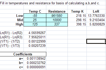
By plotting 3 different points on the temperatures/resistance, there’s a spreadsheet (Steinhart_and_Hart_Calculator) which generates the co-efficients for us.
We offload the conversion of the ADC result of the temperature to the reader which is why we are able to use the ATtiny25 for our logger.
.
Delay time changes
One thing that the SATVL doesn’t have is really customisable delay logging, initially I was going to have a programmable delay time in 4 second increments but later I went with a 1 second programmable delay. Programming the delay will be done when plugging in the logger to the reader and an example of how this can be done was found at Code at Life – AVR ATtiny USB Tutorial Part 4.
// Read delay time
byte firstByte = soft_i2c_eeprom_read_byte(EEPROM_ADDR, delayTimelocation);
byte secondByte = soft_i2c_eeprom_read_byte(EEPROM_ADDR, delayTimelocation+1);
byte thirdByte = soft_i2c_eeprom_read_byte(EEPROM_ADDR, delayTimelocation+2);
delayTime = (uint32_t) ((uint32_t) firstByte << 16) | (secondByte << 8) | thirdByte; // Combine 3 bytes
if (delayTime == blankEeprom2byte) { // Unprogrammed delay time?
  delayTime = 75; // Set 5 minutes as the default delay time
}
// Break down the delay time in 8, 4, 2, 1 seconds delay
uint32_t eightSecondsleep = delayTime / 8;
delayTime = delayTime % 8;
byte fourSecondsleep = delayTime / 4;
delayTime = delayTime % 4;
byte twoSecondsleep = delayTime / 2;
delayTime = delayTime % 2;
byte oneSecondsleep = delayTime / 1;
delayTime = delayTime % 1;
For the delay time we use the last 3 bytes (4 to make it even) of the EEPROM for this which gives us 255^3 = 16,581,375 seconds of delay time (191 days) which is more than sufficient. We need to use an unsigned 32 bit integer to store the delay time and then break down the delay time into 4 different watchdog timeouts (8, 4, 2, 1 seconds).
// Log Temperature
...
// Wait the delay time
uint32_t waitCounter = 0;
  while (waitCounter != eightSecondsleep) {
  watchdogSleep(T8S);
  waitCounter++;
}
waitCounter = 0;
while (waitCounter != fourSecondsleep) {
  watchdogSleep(T4S);
  waitCounter++;
}
waitCounter = 0;
while (waitCounter != twoSecondsleep) {
  watchdogSleep(T2S);
  waitCounter++;
}
waitCounter = 0;
while (waitCounter != oneSecondsleep) {
  watchdogSleep(T1S);
  waitCounter++;
}
Now we chain the watchdog timers together, the 4/2/1 second ones won’t execute more than a few times whilst the 8 second one will execute the most.
.
Reader code
The reader code is mostly the same as the SATVL with some modifications and code removal.
int main (void) {
  setup();
  while(1) {
    startUSB();
    SoftI2cMasterInit();
    while (1) {
      usbPoll(); // Keep polling USB until device is unplugged
    }
  }
  return 0;
}
All we do is keep polling the USB as the reader.
// This gets called when custom control message is received
USB_PUBLIC uchar usbFunctionSetup(uchar data[8]) {
  usbRequest_t *rq = (void *)data; // cast data to correct type
  if (rq->bRequest == USB_TRANSFER) { // custom command is in the bRequest field
    ...
  }
  else if (rq->bRequest == USB_DELAYTIME) { // Re-program the delay time
    dataLength = (uchar)rq->wLength.word;
    dataReceived = 0;
    if (dataLength > sizeof(replyBuf)) { // Limit to buffer size
      dataLength = sizeof(replyBuf);
    }
    return USB_NO_MSG; // usbFunctionWrite will be called now
}
When we send anything to the logger it executes this function as we know from the SATVL, we accept the data that comes in that’s for re-programming the delay time and go to the usbFunctionWrite function.
// This gets called when data is sent from PC to the device
USB_PUBLIC uchar usbFunctionWrite(uchar *data, uchar len) {
  uchar i;

  for (i = 0; dataReceived < dataLength && i < len; i++, dataReceived++) {
    replyBuf[dataReceived] = data[i];
  }

  uint32_t delayTimeProgram = atol((char*) replyBuf);

  soft_i2c_eeprom_write_byte(EEPROM_ADDR, delayTimelocation, (delayTimeProgram >> 16)); // First byte
  soft_i2c_eeprom_write_byte(EEPROM_ADDR, delayTimelocation+1, (delayTimeProgram >> 8)); // Second byte
  soft_i2c_eeprom_write_byte(EEPROM_ADDR, delayTimelocation+2, (delayTimeProgram & 0xFF)); // Third byte

  return (dataReceived == dataLength); // 1 if we received it all, 0 if not
}
We read the data received, change it to an int and then write it to the EEPROM.
.
Delay time programming
printf("Please enter in the days: ");
int delayTimeDays = 0;
scanf("%d", &delayTimeDays);

printf("Please enter in the hours: ");
int delayTimeHours = 0;
scanf("%d", &delayTimeHours);

printf("Please enter in the minutes: ");
int delayTimeMinutes = 0;
scanf("%d", &delayTimeMinutes);

printf("Please enter in the seconds: ");
int delayTimeSeconds = 0;
scanf("%d", &delayTimeSeconds);

unsigned long delayTime = 0;
delayTime += delayTimeDays * 86400;
delayTime += delayTimeHours * 3600;
delayTime += delayTimeMinutes * 60;
delayTime += delayTimeSeconds;
sprintf(buffer, "%li", delayTime);

printf("\nProgramming delay time as %li seconds...\n", delayTime);

nBytes = usb_control_msg(handle,
  USB_TYPE_VENDOR | USB_RECIP_DEVICE | USB_ENDPOINT_OUT,
  USB_DELAYTIME, 0, 0, buffer, strlen(buffer)+1, 5000);

printf("Completed\n");
For programming the delay time, we ask the user for the days, hours, minutes and seconds delay time, join all those seconds up and send the buffer string to the logger.
.
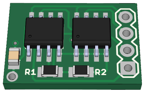
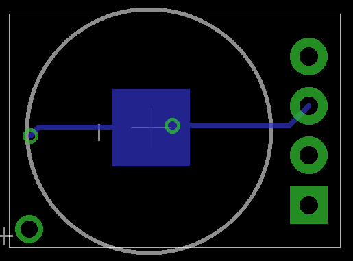
PCB design
Here is the PCB design for the logger, the size is 17mm x 12mm and originally the diode was going to go above the capacitor. Since the size is much smaller than the SATVL (41mm x 28mm), our standard CR2032 will be too large for the logger.
I happened to have some CR1220 batteries around and they fit the PCB nicely however the actual CR1220 battery holder doesn’t look like it would fit the PCB.

I found that if you removed the 2 metal pieces of the CR2032, they can become the battery holder (though it’s not as secure as a proper battery holder).
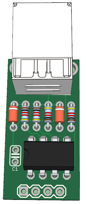
For the reader it looks a similar to the SATVL.
.
Battery life
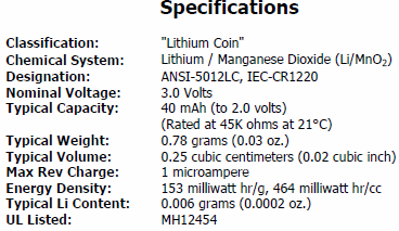
One problem with going with a CR1220 is that it only has a capacity of 40mAh.
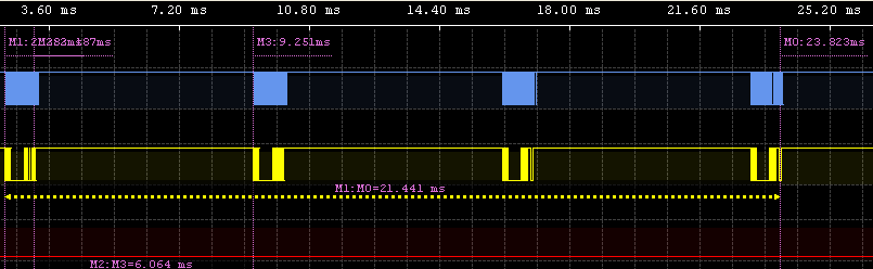
Using my logic scanner I could find out how long the EEPROM writes lasted which was 28ms (21ms + 6ms) and using the SACL I measured the peak current when writing to the EEPROM to be 2mA.
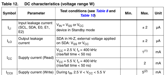
The M24512 datasheet says that writing to the EEPROM can draw 5mA so just for simplicity and the worst case scenario I’m saying that 5mA will be drawn during the 28ms.
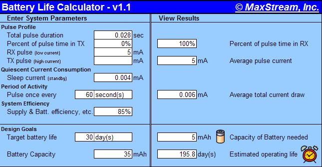
With the delay time as 60 seconds, the battery should last for 195 days which isn’t too bad.
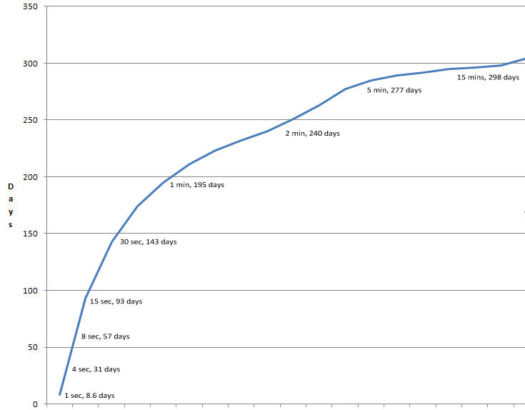
I’ve made a chart to show how the different logging times far up, as you can see using a delay time of under 8 seconds will make the battery not last very long.
.
Testing
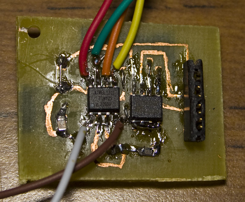
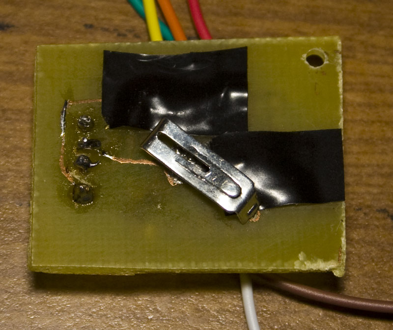
I moved the components of the PCB around so that I could easily solder each component down since I made a test PCB at home, looks pretty bad but it’s functional.
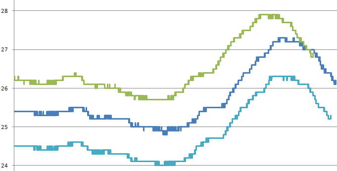
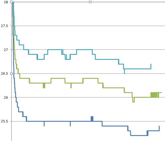
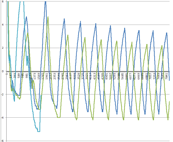
Here are some results with a 4 second delay time, there seems to be a 1.5C -/+ spread between the loggers readings and you’ll also note that some loggers finish earlier than others which is due to the 10% -/+ accuracy of the timer.
Whilst testing I found that if I connected a 2.2K resistor to the CR1220 batteries, they would drop to 2.6V, sometimes less. That’s a problem because the ATtiny25 and EEPROM I ordered were 2.6 – 5.5V but luckily there are 1.8 – 5.5V variants available too so I’ll need to order them in. The batteries that I was using were taking from existing products so they weren’t brand new.
On the last graph, you can see one logger drop off, I believe that this was because the battery had low voltage – re-testing with a CR2032 plugged into the headers seemed to correct the issue.
Download A25TTL_v1.0
The A25TTL seems to work correctly, I’ll continue to do more testing, wait to receive the new CR1220 batteries and the AVR/EEPROM to see how well they perform, and the PCBs are in the works.


Dear Alex,
If you do not recall, I am the guy who is involved in the “FalconFlight” project where we needed a small package and temperature sensing at 1 sample per second.
This version looks really great…..I would like to follow as it develops.
But it is necessary for me to purchase a 2nd copy of the original 512K package to act as a backup for our:
Ver 1.2 of
Standalone Temperature-Voltage Logger (with voltage logging)
Item Number SATVL-VA-512K , EEPROM options: 512Kbit
As part of the project, we are planning on helping some novice soldering folk assemble the package. The teams are made up of 10 year old kids and 70 year old kids:)
I will place the order as soon as I finish this message….
Thanks for your great designs…
Kent Smith
The “FalconFlight” project
ps I will send you an e-mail of some of the project planning just for fun….let me know what you think;)
[…] are premade spreadsheets that you can download which will generate S&H constants, or you can build your […]