When I was placing an order for some parts I happened to find an I2C digital potentiometer (MCP4017T) on special at 4 cents each, so I bought some and now that I re-check the price they are 70 cents each.
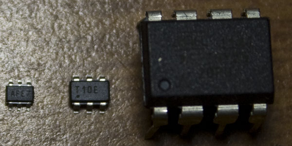
The package it comes in is a SC70-6 which is even smaller than the ATtiny10 (side by side comparison above, ATtiny85 on the right too).
Digital potentiometers can be useful if you want to change your resistance without tweaking your pot with a screwdriver, the example which I’ll be showing is adjusting the contrast on an 16×2 LCD module, it can make your project be more professional if you had it all inside a case. Another use could be an op-amp with an adjustable gain.
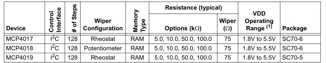
There are different pot options you can go with – 5K, 10K, 50K or 100K, I went with the 10K version. With a 10K pot, you can adjust it from 0 ohms to 10K ohms in this case in 128 steps of 75 ohms.
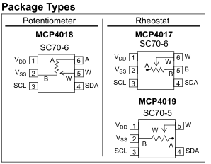
I have the Rheostat version and our variable resistor is at the W and B pins.
For the contrast on a 16×2 LCD normally you connect a 10K pot, I measured the resistance value that works well is 700 ohms. So how would you use this on your project? When you power up your device you could load the default value that you know works well to the digital pot and then have 2 buttons so the user can adjust the contrast. In my example, we’ll be adjusting the resistance by issuing serial commands.
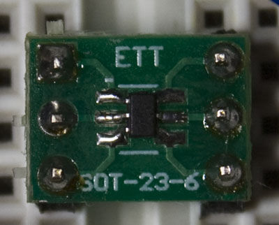
I soldered it to a SOT23 breakout board with lots of flux and it fit in well.
Pin 1 - VCC
Pin 2 - GND
Pin 3 - SCL to Arduino A5
Pin 4 - SDA to Arduino A4
Pin 5 - GND
Pin 6 - 16x2 LCD VO (contrast adjust)
Now we’ll modify the LiquidCrystal Library – Hello World sketch.
// include the library code:
#include <LiquidCrystal.h>
#include <Wire.h>
#define pot_address 0x2F
The MCP4017T has a static I2C of 0101111.
lcd.setCursor(0, 1);
// print the number of seconds since reset:
lcd.print(millis()/1000);
delay(100);

char readInput[10];
int readCount = 0;
while (Serial.available() > 0) {
  char c = Serial.read();
  readInput[readCount] = c;
  readCount++;
}
readInput[readCount] = '\0';

if (readCount >= 1) {
  int readin = atoi(readInput); // Read input

  // Write to digital pot
  Wire.beginTransmission(pot_address);
  Wire.send(readin);
  Wire.endTransmission();

  // Write to serial monitor
  Serial.print("Sent - ");
  Serial.print(readin);
  Serial.print(" = ~");
  Serial.print((readin+1) * 81);
  Serial.println(" ohms");

  // Display ohms on LCD
  lcd.setCursor(0, 0);
  lcd.print((readin+1) * 81);
  lcd.print(" ohms    ");
}
After printing anything on the LCD, we read the serial input and all we need to do is send the I2C address and the value we want it to be set to. We print the approximate ohms that we’ll have it set to, I found that about x81 seems about right. Download lcd_with_i2c_digital_pot
https://www.youtube.com/watch?v=60rjWM1swA0
The top row is the ohms we’ve set it to and the bottom row is the Arduino time since on (I’ve left it as is). When we send 0 to the pot, it gives us the lowest resister value about 75 ohms (it’s really 100 ohms when you test with a multimeter). Each time you increase the value, the screen starts getting lighter as the resistance increases.


