From Part 6.5, the PIR PCBs arrived and now I’ve got all the PIR sensors (except 1) on them. When I connected up these PCBs to the PIRs I found that randomly they would go off when the alarm server had them switch on. Eventually I found that the modification I made to the broken PIR had to be made to all PIRs.
What I’m looking to do now is to see which sensors are checking in with the server which will also serve as a way to check if the 3V battery for the PIR PCB has gone flat. When the PIRs/Siren are sending their random number to check in, the last byte is 0 or 1 to say if they are a PIR or Siren.
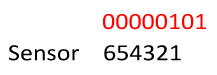
By modifying the higher bits of the last byte to say which device it is. For example, 00000101 would mean sensor 1 has checked in.
#define SENSOR_NO 1 // 1 to 6
// Set last data_out number to 0 to indicate to the server that we are a PIR
data_out[20] = (1<<(SENSOR_NO+1));
We define our sensor number which we need to change for each PIR/Siren and then shift 1 to the appropriate place.
data_in[20] = data_in[20] & 0x01;
if (data_in[20] == SIREN_REQUEST) {
For the server we just need to ignore any of the higher bits and check the last digit only (by using & 0x01) and now it all works together just fine.
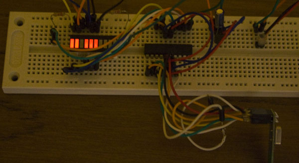
We can move on to the check in sensor now, I went with the ATtiny261 because I didn’t have any other chip available and we can use all of PORTA pins for the LEDs. We’ll make it check for the last byte and light up the LEDs corresponding to the sensor which has checked in, then after approximately 1 minute we can reset all the LEDs.
RX_POWERUP;
mirf_flush_rx_tx(); // Flush RX and TX FIFO
mirf_CE_hi; // Start listening

// Wait for incoming requests
while (!(mirf_status() & (1<<RX_DR))) {
  _delay_us(250);
}
mirf_CE_lo; // Stop listening

for (int x = 0; x < 21; x++) {
  data_in[x] = 0; // Clear the data_in
}

mirf_CSN_lo; // Pull down chip select
spi_transfer(R_RX_PAYLOAD); // Send cmd to read rx payload
spi_read_data(data_in, mirf_PAYLOAD); // Read payload
mirf_CSN_hi; // Pull up chip select
mirf_config_register(STATUS,(1<<RX_DR)); // Reset status register

for (int x = 1; x < 8; x++) {
  if (data_in[20] & 1<<x) {
    PORTA |= 1<<x;
  }
}

// Timer overflow, reset PORTA to low
ISR(TIMER0_OVF_vect) {
  PORTA = 0;
}
The code is similar to the server code, we wait an listen for a sensor to connect, clear and read the data in and now just loop over the last byte’s bits and turn on the corresponding LED. When the timer reaches 1 minute it turns off all the LEDs.
Because I have auto acknowledge on the nRF24L01 this means that if we are listening in on the communication between the sensor and server, we’ll be sending auto acknowledgements which does interfere with the sensors. I tried to turn off auto acknowledge but that turns out to stop incoming packets from being received by us.
Next whilst listening as the server, I didn’t set up the TADDR or the RX_ADDR_P0 which means that we will still auto acknowledge but the acknowledge packet will be shown as coming from some other address (default is 0xE7E7E7E7E7) and the sensor should receive that reply and ignore it since it doesn’t match the address it expects – “serv1”.
Download Alarm_SM_v0.3a.
It all works now and I’m happy with how everything is working at the moment.
Part 1
Part 2: Two way communication for PIR sensors
Part 3: Secure communication
Part 4: Adding on sirens and SMS sending
Part 5: Modifying the PIR sensor
Part 6: PIR PCB
Part 6.5: PCBs arrived
Part 7: See which sensors check-in
Part 8: Building our own alarm system
Part 9: Remote control and attempted improvements
Part 10: Prototype PCBs


