Following on from Part 3, we looked at securing the communication between the PIRs and the alarm system. This part was going to be on PIR and the extra steps I ran into when adding the PIR client to it but we’ll leave it for next time. In this part we’ll look at the adding the sirens, SMS sender and the modifications needed to the server.
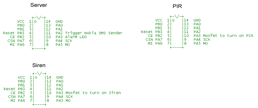
We’ve upgraded to the ATtiny84 so we can use an extra pin or two, below is how we are utilising each MCU.
Adding on the sirens
Originally my plan was to have the sirens listening for when the server would contact them – it worked but it was a bit complex when it didn’t need to be.
A downside of it was now that the sirens were always listening it would take up more power – my plan was to connect a 12V 7A battery to the sirens and if always listening (drawing 15mA) that would last a few weeks or so.
I decided to re-use the same code that the PIRs use – contact the server every x seconds which for the sirens will have to be quicker than PIRs so the server can continue on with what it needs to do. We can add a timeout to do this.
// Sleep for 1 seconds
setup_watchdog(T1S);
system_sleep();
turnOffwatchdog();

// Switch off the siren after ~10 minutes if we don't hear anything back from the server to turn the siren off
// 600 seconds / (1 second watchdog + 50ms random block)
if (ten_minute_counter >= 571) {
  PORTA &= ~(1<<PA3); // Turn off siren
  ten_minute_counter = 0;
}
ten_minute_counter++;
We sleep for 1 second and also have a 10 minute counter to turn off the siren if we haven’t been able to check in with the server.
// Increment our 256bit random number
...
// Generate the random block (160 bit) using SHA1 from our random number
...
// Check in the with server
if (check_in()) {
  // Perform alarm siren action
  if (alarm_siren == ALARM_ON) {
    PORTA |= (1<<PA3); // Turn on siren
    ten_minute_counter = 0;
  }
  else {
    PORTA &= ~(1<<PA3); // Turn off siren
  }

  // Sleep for 2 seconds so other sirens can check in
  setup_watchdog(T2S);
  system_sleep();
  turnOffwatchdog();
}
After checking in with the server and it’s given us the alarm on action, we turn on the siren and reset the ten minute counter. We sleep for 2 seconds to give the other sirens a chance to check in.
Siren with Mosfet
The siren draws 1.6 amps and was bought from Ebay, when triggered we power it using a mosfet. I don’t think I’ve discussed power dissipation of mosfets before but I did find a website to help explain this for us – http://mcmanis.com/chuck/robotics/projects/esc2/FET-power.html
With mosfets to calculate the power dissipation the formula is P=I2R where I is the current and R is the RDS(on) resistance which is the resistance between the drain and source of the mosfet – where your load’s current flows. I’m using a STP22NF03L TO220 package that has a RDS(on) @ 5Vgs of 0.06 Ohms max at 25C.
First we need to find out how much watts our mosfet can handle without a heatsink at 25C. 175C thermal junction max – 25C ambient / 62.5C junction to ambient per Watt gives us 2.4 watts.
Now we can use our P=I2R formula: P = 1.6A2 x 0.06 gives us 0.1536W – no where near the maximum so we are all good.
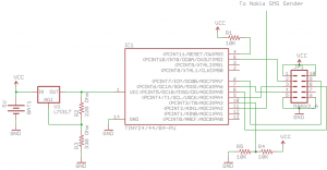
Schematic
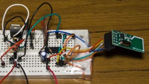
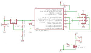
I’m using a LM317 regulator to reduce 12V to ~3V for the ATtiny and the Mirf module.
Modifications to the server
void process_siren_check_in(void) {
  // Change the TX address to be the siren clients
  mirf_write_register(RX_ADDR_P0, TADDR_SIREN, 5);
  mirf_write_register(TX_ADDR, TADDR_SIREN, 5);

  // Connect to sirens for 4 seconds
  siren_listen();

  // Go to sleep until the alarm is de-activated or re-activated by a pin change
  if (alarm_siren == ON) {
    system_sleep();
  }

  // Connect to sirens for 4 seconds
  siren_listen();

  // Change the TX address back to be the PIR clients
  mirf_write_register(RX_ADDR_P0, TADDR, 5);
  mirf_write_register(TX_ADDR, TADDR, 5);
}
The siren has a different address than the PIRs so we need to firstly we change RX acknowledge and TX addresses to be of the sirens. We listen for incoming requests for 4 seconds and then go to sleep if the alarm siren is still on. I’ve found that the alarm turns itself off after about 5 minutes or so. When that happens or when we turn it off ourselves, we listen again to the siren requests so we can turn them off and change the RX/TX address back to the PIRs
void siren_listen(void) {
  // Start Timer1 to count for 4 seconds
  TCCR1B = ((1<<CS11) | (1<<CS10));

  // Listen to requests from sirens for 4 seconds
  while (four_second_timeout != true) {

    RX_POWERUP;
    mirf_CSN_lo;
    spi_transfer(FLUSH_RX);
    mirf_CSN_hi;
    mirf_CE_hi; // Start listening

    // Wait for incoming requests from the sirens as long as the 4 second timeout hasn't been reached
    while (!(mirf_status() & (1<<RX_DR)) && four_second_timeout != true) {
      _delay_us(250);
    }
    mirf_CE_lo; // Stop listening

    // Process the request
    ...
  }

  // Stop Timer1, reset the timer counter and 4 second timeout
  TCCR1B = 0;
  TCNT1 = 0;
  four_second_timeout = false;
}
We set a timeout period of 4 seconds before listening to the sirens and then after 4 seconds we reset the timers. One thing which I haven’t realised before was when turning off the timer is that you need to reset the actual counter (TNCT1) on the timer too.
One problem that will happen is that the siren’s requests will interrupt the server when it’s listening to PIR check ins and vice versa.
// Generate the random block (160 bit) using SHA1 from our random number
sha1(data_out, random_number, 256);

// Set last data_out number to 0 to indicate to the server that we are a siren
data_out[20] = 1;

// Check in the with server
if (check_in()) {
  ...
The fix to this is that when the PIR or siren transmits the random number it’s only 160bits (20 bytes) and we send 168bits (20 bytes + 1 empty byte), we can change the last byte to be the indication byte – 0 for the PIR and 1 for the siren.
while (!(mirf_status() & (1<<RX_DR)) && four_second_timeout != true) {
  _delay_us(250);
}
mirf_CE_lo; // Stop listening

// Read the random number
if (mirf_receive_data()) {

  // Check if the request came from a siren
  if (data_in[20] == SIREN_REQUEST) {
    ...
And the server side.
One more thing I found is that if you transmit more than 15 bytes with an ACK you should change the auto-retransmit time to be more than 500uS, we aren’t doing that however I thought it might be a good idea to increase the auto retransmit time from 250uS to 500uS just in case that might be an issue further on.
Schematic
We also use a LM317 regulator as the alarm is powered from a 5V regulator. Since the alarm LED is also at 5V we use a resistor divider to bring that down to 2.5V.
Adding the Nokia SMS Sender
This is the easiest part since previously the Nokia SMS Sender was configured to send us a SMS when the a blackout was detected, all we need to do is change the message it sends. I wanted it to send us the SMS as quickly as possible so it just sends “On” or “Off” and it selects the pre-stored number from the phone. The phone is always left on with the charger plugged in so it’s ready to send the SMS at any time. If we wanted to we could do this done wirelessly by adding a “siren” client to it.
Overview
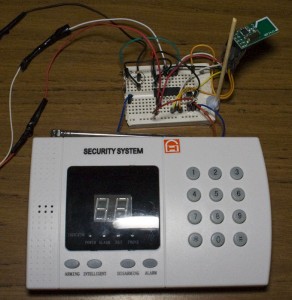
Here is the overview of the system as it stands. Download AlarmSM_v0.1.
- Server – We have covered this is part 2/3. When powered on it is always listening for PIR check ins and monitoring the alarm system LED. If the LED is off the alarm system is off, if the LED is blinking the alarm system is on and if it’s solid on the alarm system has triggered. When the alarm system triggers, we trigger the SMS sender, we listen only to the siren’s requests, go to sleep until the alarm state changes, we trigger the SMS sender, listen to the siren’s requests again and go back to listening to PIRs.
- PIR – Contacts the server every 8 seconds to know the alarm state. If alarm state is on then turn on the PIR on.
- Siren – Contacts the server every 1 seconds to know the alarm siren state. If alarm siren state is on then turn on the siren on.
- Nokia SMS Sender – When triggered on or off, send an SMS to the nominated number.
For the next part we’ll look into the adding the PIR client circuit to the PIR and the issues I ran into with it.
Part 1
Part 2: Two way communication for PIR sensors
Part 3: Secure communication
Part 4: Adding on sirens and SMS sending
Part 5: Modifying the PIR sensor
Part 6: PIR PCB
Part 6.5: PCBs arrived
Part 7: See which sensors check-in
Part 8: Building our own alarm system
Part 9: Remote control and attempted improvements
Part 10: Prototype PCBs
