Following on from Part 5, we looked at using optocouplers to turn on the PIR’s reset until the PIR settled down otherwise it trigger the alarm. In this part we’ll add on the code to save the 256bit random number to the EEPROM when the power is disconnected, reduce the NRF24L01 power consumption when we are sleeping and look at the PCB made for the PIR.
Detect battery removal
The reason we need to save the 256bit random number to the EEPROM is so when we power on the PIR again, the random number doesn’t start from the initial random number we programmed. We need to add a capacitor of sufficient size to keep the ATtiny84 running for a few milliseconds to save data to the EEPROM. After some testing I found that a 1000uF capacitor was more than sufficient for this task.
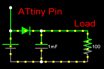
The easiest way I could think of detecting whether the 3V battery was removed was to use a sckotty diode from the 3V battery going to the capacitor, have a wire connected to the 3V battery to the one of the ATtiny’s pins. The ATtiny and NRF24L01 run from 2.6-7V after the voltage drop, both will run just fine.
We also need to add a load resistor on the 3V battery itself otherwise the wire going to the ATtiny pin would be floating. A 4.7Mohm resistor should be enough to pull it to ground and also be a high enough value to not draw much current from the battery.
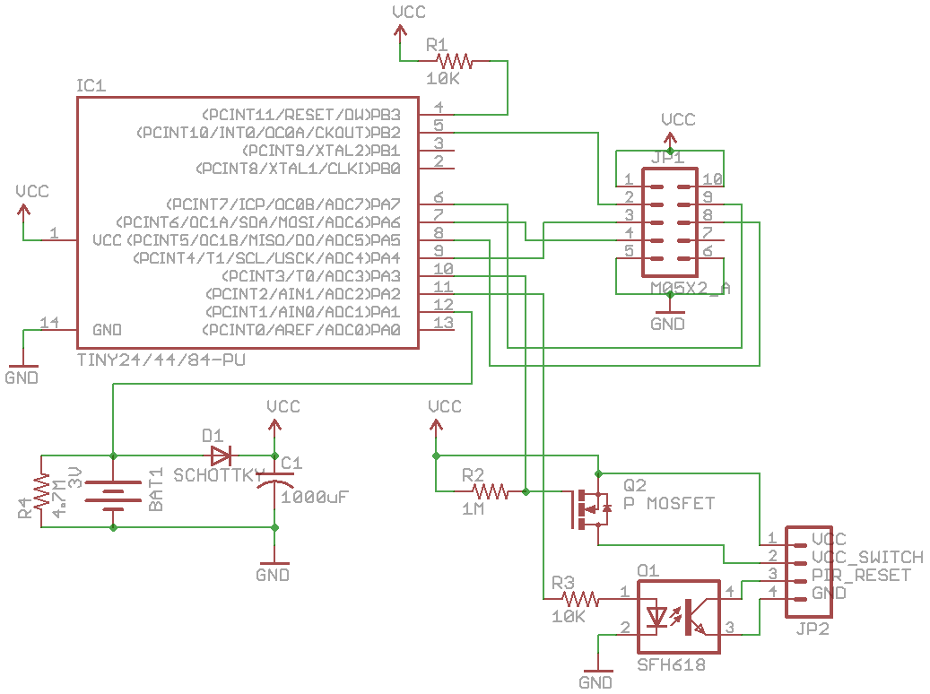
Here’s the schematic – I’ve replaced the N mosfet with a P mosfet and have also changed the 100k resistor on the mosfet to be 1M ohm once again to reduce current on the battery.
Save random number to EEPROM
// Pin change means the battery has been removed, save the random number to the EEPROM
ISR(PCINT0_vect) {
  POWERDOWN; // Power down the nRF24L01
  PORTA |= (1<<PA3); // Turn off PIR (P mosfet)

  // Write the 256bit random number in the EEPROM
  for (int x = 0; x < 32; x++) {
    eeprom_write_byte((uint8_t*) x, random_number[x]);
  }

  // Write to the EEPROM first boot location if this is the first time the ATtiny has booted since being programmed
  if (firstBoot == blankEeprombyte) {
    eeprom_write_byte((uint8_t*) firstBootlocation, 0);
  }

  // Wait for the capacitor to be discharged
  _delay_ms(10000);
}
Above is the code, we just add a pin change interrupt, save the random number and write 0 to the firstBootlocation on the EEPROM.
// Read random number from the EEPROM if this isn't the first boot of the ATtiny after programming
firstBoot = eeprom_read_byte((uint8_t*) firstBootlocation);
if (firstBoot != blankEeprombyte) {
  for (int x = 0; x < 32; x++) {
    random_number[x] = eeprom_read_byte((uint8_t*) x);
  }
}
When starting up the ATtiny we check the firstBootlocation, if it isn’t blank (by which I mean it reading 255) then we know we have a random number to read from the EEPROM, easy.
Powering down the nRF24L01
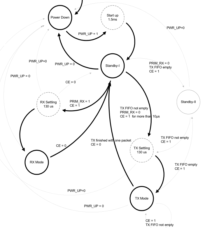
Usually after the nRF24L01 has sent or received data, it goes back to Standby-I mode.
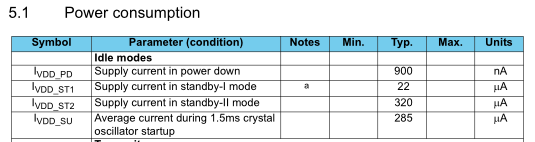
If you saw in the code above we use POWERDOWN to put the nRF24L01 in power down mode. By powering down we’ll drop down from 22uA to 900nA. When we want to start up from power down we can use TX_POWERUP or RX_POWERUP and then wait a minimum of 1.5ms.
Based on the power down mode and change in resistors we can calculate our new battery life. I measured 10uA when it was sleeping but wasn’t able to correctly measure how much current when it would be so I estimate 15mA like before. I’m also assuming the worst case scenario which is that the nRF24L01 is powered up for 10ms (normally it should be 1-2ms to send and receive if there are no retransmissions needed).
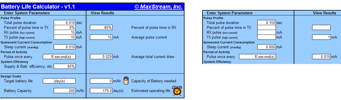
We also have to account for the 150ms or so when the PIR generates the SHA1, I found another Battery Life Calculator which gives identical results to the previous one I used however since it’s a spreadsheet we can now account for the PIR generating the SHA1 (on the right of the picture) and add both of them together. The result gives us 179 days on a 240mAh battery. If we decided to go with a delay time of 16 seconds instead of 8 seconds, we would get 295 days, so it’s something for me to think about.
PCB
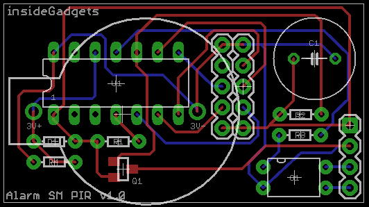
Download AlarmSM_PIR_v0.2 which includes the Eagle schematic and PCB.
Here’s the PCB I made, the battery is on the bottom of the board and the nRF24L01 would be mounted on 2 lots of female headers so it’s just above the ATtiny84 and faces to the left. I was attempting to make this PCB at home but with the double sided connections to most of the components I found it wasn’t worth it so I’ll order the boards and wait a month for them to arrive.
Part 1
Part 2: Two way communication for PIR sensors
Part 3: Secure communication
Part 4: Adding on sirens and SMS sending
Part 5: Modifying the PIR sensor
Part 6: PIR PCB
Part 6.5: PCBs arrived
Part 7: See which sensors check-in
Part 8: Building our own alarm system
Part 9: Remote control and attempted improvements
Part 10: Prototype PCBs


