When you work in IT, you see all kinds of network cables, some are labelled, some aren’t, some places I can imagine have a mess of cables so I thought how could tracing a cable be easier? I know that cable tracers exist but you have to unplug the network cable in order to trace the cable, how about making an in-line network cable tracer that you can install once and leave it there?
(sneak peak of the outcome)
My first thought was to somehow fit LEDs to existing cables and have a button which would light up the cable but this means that all network cables would need to be replaced so this isn’t suitable. So it’s time to take a look at a network cable and what we can do with it.
From Wikipedia, we can look at the wiring scheme where we have 2 pairs of cables used for transmitting and 2 pairs of cables for receiving.
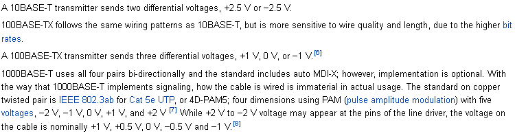
The voltages which are being transmitted in these lines varies depending on the speed the network card/switch negotiate at but it can be between -1V to 1V or -2V to 2V. Ethernet uses differential signaling so that if there was any noise in the environment, it would be picked up by both pairs and then it can be subtracted from the signal.
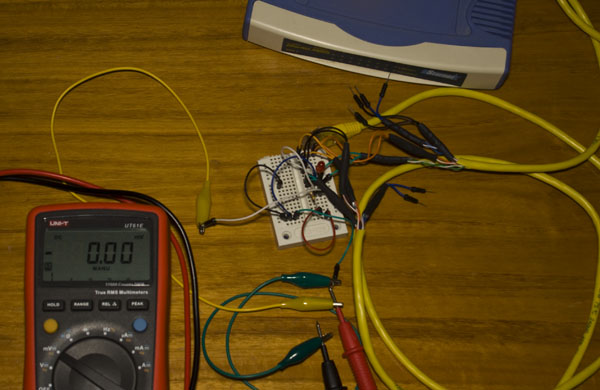
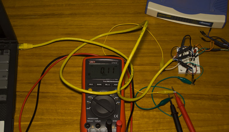
I was using a 10/100Mbit switch when I hooked up my multimeter to the RX- and RX+ (green) cables I didn’t see anything close to the voltage specified. However when I hooked up an LED, it was blinking randomly so there is a voltage of 1.8V or more present between the two wires. When in frequency mode I was detecting a few hundred Hz to 2KHz.
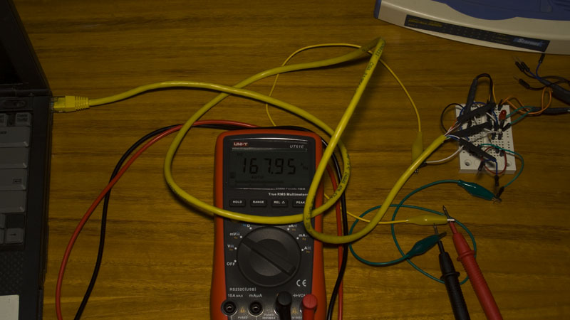
When I plugged in my laptop to the other end of the cable, the LED didn’t light up this time and my multimeter read 11mV whilst the frequency was locked at 167 KHz.
My idea is to introduce a short pulse on the RX- and RX+ lines so that it’s picked up by the receiving end and the pulse would need to be generated by a coin cell to keep things simple.
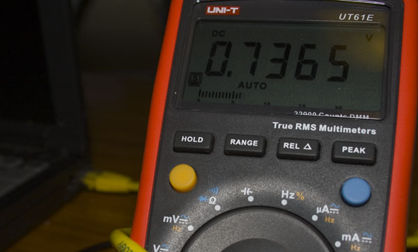
The first thing I did was hook up a 3V coin cell battery to both lines which would short out the battery, it had enough power to disconnect my old laptop from the network. You can see that my multimeter detects only 0.8V drop between the two lines when I shorted the battery. (I tried to take a picture of the small network LED on the computer which turned off)
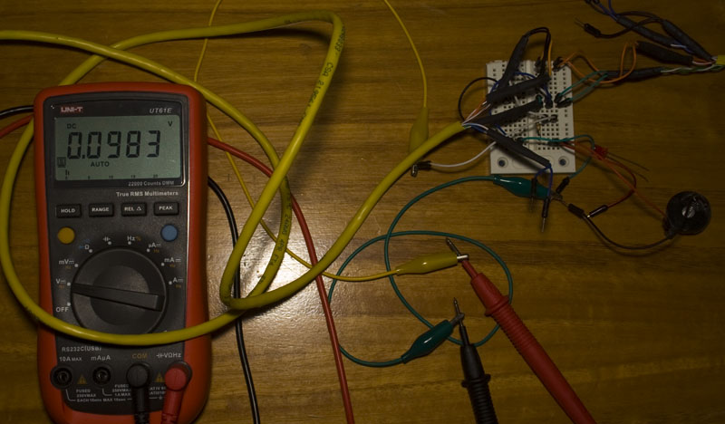
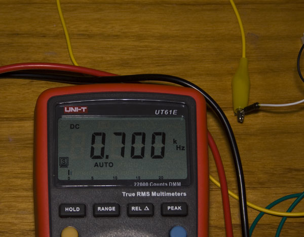
Next I played around with limiting the current being delivered and found that 47 ohms was the sweet spot, there was a 0.1V drop between the lines. When the 3V battery is connected you do notice some packet loss but it’s not enough to disconnect the laptop.
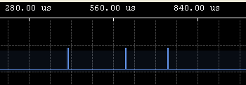
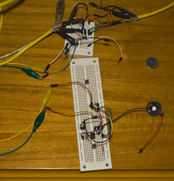
I got out my logic analyser and switched to 1MHz to see if I could pick up the signal which I was able to – it’s a bit jittery but should be good enough.
When I hooked up my Arduino and read the state of the input pin all I got back was 0. Next I tried reading the ADC and did get a result that was jumping around 0 to 40 and rarely up to 100. When hooking up the 3V battery with resistor I got about 20 or more for a few readings but it seems to impact the network when the ADC is running. This sort of works but it can’t be our final solution as the battery won’t last and it doesn’t give us a really accurate result. Next I tried using differential ADC which didn’t affect the network but gave similar results.
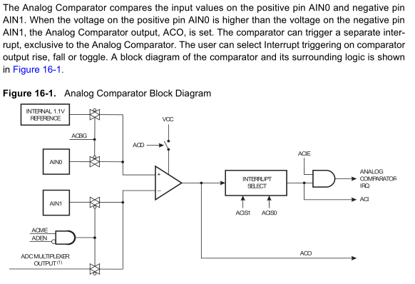
I was playing around another feature of the ATtiny that I haven’t used before – the analog comparator. There are 2 pins, the positive and negative pins, so if the positive is higher than the negative pin, ACO reads 1. You can have it generate an interrupt on rising ACO edge, falling ACO edge or on ACO toggle but the comparator is switched off when in power down sleep mode.
The code I’ll be using to test my circuits is:
if (ACSR & (1<<ACO)) {
  PORTB |= (1<<OutPin); // Set LED high
}
else {
  PORTB &= ~(1<<OutPin);
}
If you ground both AIN0/1 – the LED switches off, connect them together – the LED switches on and leave the wires floating – the LED switches on.
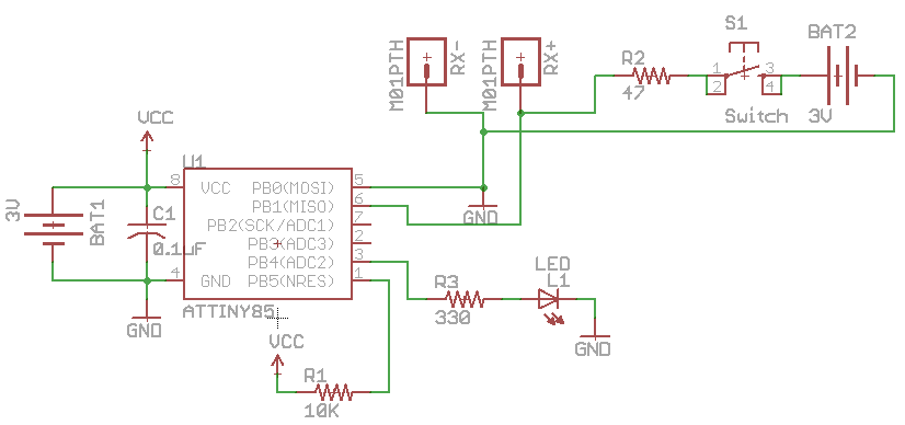
I was only using a multimeter and when you connect it up, it does influence the circuit. The above schematic shows that RX- on RJ45 Pin 6 is connected to AIN0 (PB0) positive and RX+ on RJ45 Pin 3 connects to AIN1 (PB1) negative.
When the switch is off, the difference between RX- and RX+ is 1.7mV or so which means the negative is 1.7mV higher than the positive so the LED stays off. When the switch is held down, you see a small blink of the LED and that’s about it. The voltage drops to -45mV which means the AIN0 positive is now at higher voltage.
Also if the network cables on either end are disconnected, the LED stays on – this could be a feature or something we want to remove later on. If both network cables are disconnected, then the LED turns off.
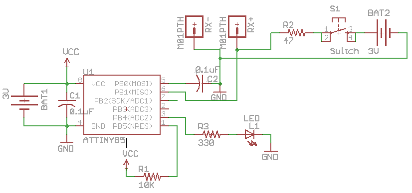
Now I wanted to make the LED blink or stay on when the switch was held down and after spending some time playing around with grounding, resistors, capacitors I found that adding a capacitor between ground and the AIN1 (PB1) pin seemed to make it blink quite a few times a second.
The next problem is that if you leave this circuit powered on, the receiving performance when transferring files is badly affected, from 7MB/s down to 200-800KB/s.
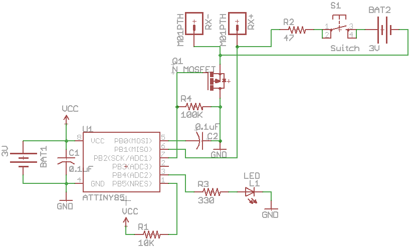
We can solve this by using a N mosfet on the AIN1 (PB1) pin as it’s already grounded and change our code to sleep for 1 second, turn on the mosfet, check the analog comparator a few times, turn off the mosfet and then turn the LED if the output was high. Download INCT_v0.1
Tested and working well. Switching the mosfet on and off every second for under 1ms doesn’t seem to affect the network much at all, maybe 100-200KB/s slower and you may notice the occasional packet loss when the ATtiny checks the RX pins. What I haven’t done is test with PoE switches/devices or gigabit ethernet.
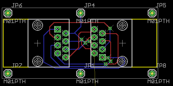
As soon as I had this idea, I started designing the PCB before I figured out my final solution. I’m thinking that it would look like a PoE injector module – 2 RJ45 ports on each end and you’d use some small 0.2m network cables to joint it up on both ends. The ATtiny and other components would be on another board mounted on the bottom.
For the next part I’ll complete the PCB, do testing on a gigabit network (unfortunately I don’t have an PoE devices/switches) and see if I can improve analog comparator testing code to reduce the time spent in there.


Nice guide and tips that everyone can refer through. Thanks for it.