Whilst waiting for the analog switch to arrive as mentioned in Part 2, I decided to try out a gigabit network switch.
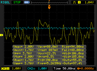
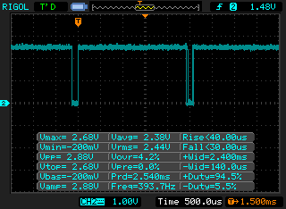
The waveform is faster than the 100Mbit switch but is essentially the same however this time when I connected the diode and 0.1uF capacitor (to form a peak detector) and tried copying data over the network it would slow down and when connecting the 47 ohm resistor the network would drop out.
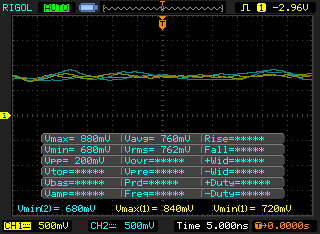
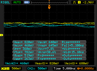
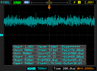
After reducing the capacitor to 10pF it doesn’t drop out anymore and playing around with the resistor I found that a 330 ohm resistor worked well and I also added a 4.7M ohm resistor on the cap. The problem that I found is that the resistor divider’s input (yellow) and output of the peak detector (blue) is a bit noisy, on the left we have how it looks normally and on the right when the 330 ohm resistor is applied, as you can see there isn’t much difference between them – about 100mV average drop.
I had to adjust the resistor divider to be very close to the peak detector output so this is another problem how to adjust the resistor divider to suit the network switch – we can use a digital pot to adjust it automatically however there certain points in the waveform that could incorrectly trigger the LED.
So we’re back to again to looking into using the ADC, this time when using the ADC I didn’t notice any issues which must be because of the diode capacitor (peak detector) configuration being used. I outputted a high signal and kept it high until we reached the ADC value – now when I read out the ADC value I get about 2.8ms high without the 330 ohm resistor applied and 2.4ms with it applied so there is a noticeable difference between them.
Even though the signal has a high peak to peak, when running the ADC it only fluctuates by a little bit so we have something to work with.
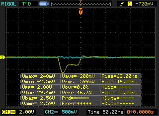
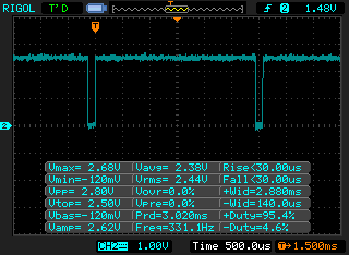
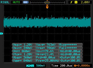
I also found that when the computer is plugged in but not turned on, the switch ports colour changes back to 10/100Mbit mode and we see the signal above on the scope. The INCT won’t be able to detect this small pulse so it will think that the network cable is disconnected.
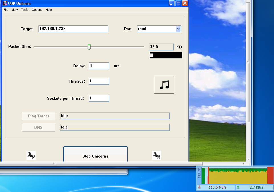
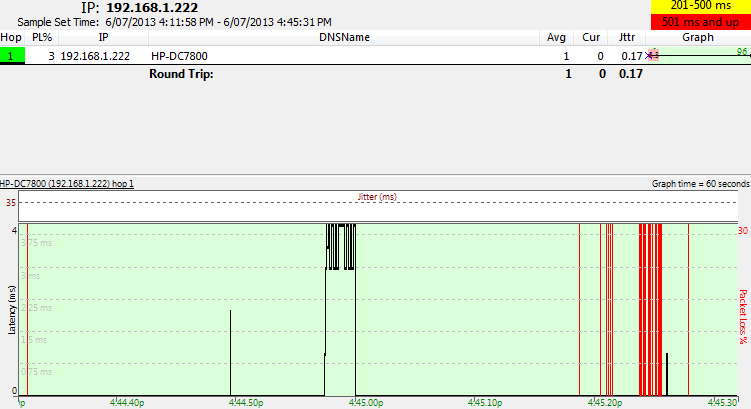
After transferring data across from a PC to a laptop however I was only getting 40-50MB/s but I need the full speed to really test it out. I found a program called UDP-Unicorn to send UDP packets as fast as possible to the laptop, now I’m getting 100-112MB/s which is the fastest gigabit can offer and also I used Ping plotter to plot the pings every 0.1 seconds.
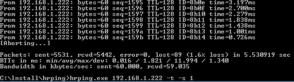
I found another program called HRPing which allows you to ping a host quicker than the windows default to give us greater resolution than what ping plotter did. When inserting or removing the 220 ohm resistor we can see that packet loss does occur for a little bit, when I look at the analog switches we’ll see if this changes.
int highReading = 0;
int highReadingClear = 0;
bool ledon = false;

while (1) {
  int adcValue = analogRead(ADCpin);

  // If close to 0 reading then the wire is disconnected
  if (adcValue < 30) {
    PORTB |= (1<<ledpin);
  }

  // Only do something if the current and last reading is more than the disconnected wire rate
  if (adcValue > 30 && highReading > 30) {
    int difference = highReading - adcValue;

    // Check for high to low transition of 200mV, the difference between last reading and adcValue
    if (difference > 68) {
      PORTB |= (1<<ledpin);
      ledon = true;
    }
    else if (highReading - adcValue < 17) { // Has it risen to 50mV near the high point or exceeded it?
       ledon = false;
       PORTB &= ~(1<<ledpin);
       highReadingClear = 0;
    }
  }

  if (ledon == false) {
    if (highReadingClear >= 20) { // Clear the high level every sec
      highReading = 0;
    }
    if (adcValue > highReading) {
      highReading = adcValue;
    }
    highReadingClear++;
  }

  _delay_ms(50);
}
Now for the code, we do an ADC reading and if it’s under a reading of 30 (0.08mV) we assume the cable has been disconnected and the LED goes on. Whilst running and there is a network cable plugged in, we keep collecting the ADC readings, find the highest reading and reset this reading after 20 ADC readings (just in case there are spikes that could happen which trigger the LED but I haven’t seen that happen at all).
If we find that the reading goes high to low with a difference of 200mV or more then we assume that the 220 ohm resistor was applied and the LED goes on. When the 220 ohm resistor is removed, the reading will eventually reach the high reading or if we are 50mV close to it then the LED turns off. Download INCT_v0.2


