From Part 3, we tested out the INCT on a gigabit network and made some changes to the resistor and capacitors, now that the analog switch has arrived we can try switching between the RX/TX lines to the peak detector. The reason we need an analog switch is that we need to isolate the RX-/+ and TX-/+ lines from each other.
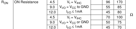
An analog switch is just that, a switch which joins two wires together that is activated by driving the control pin either high or low. I went with the M74HC4066 which has minimum supply voltage of 2V and a quiescent supply current maximum of 1uA at 25C which is pretty good. We also need to keep an eye on the resistance of the switches when they are on, as it will never be 0 ohms, the maximum of 170 ohms should be ok.
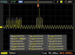
When re-testing my current configuration without the analog switch I found that if I removed the one of the two network cables the LED would go off as expected but then a short time later it would flicker a little bit. Checking the scope I found some spikes were occurring and if I reversed the RX-/+ lines the issue went away – so I guess there is a specific way that lines should be connected. Also I found that you shouldn’t leave any control pin floating as that cause the analog switch to draw more current (about 100-200uA).
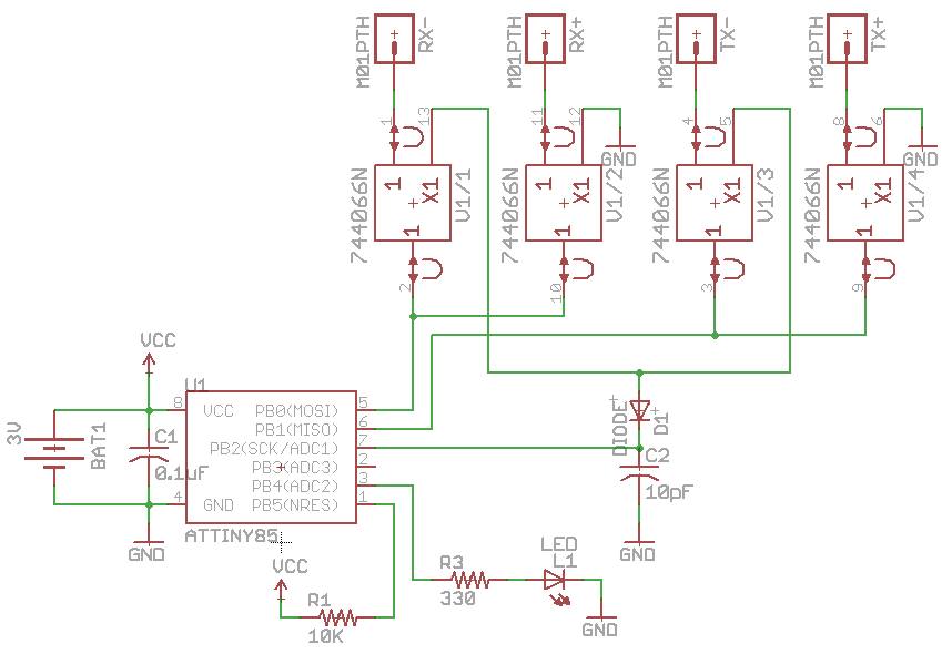
Here’s how the analog switch connects to the RX/TX lines, let’s check the updated code.
while(1) {
  // Turn on the RX or TX
  if (currentlyReading == RX) {
    PORTB |= (1<<RX_switch_pin);
  }
  else {
    PORTB |= (1<<TX_switch_pin);
  }

  int adcValue = analogRead(ADCpin); // Read ADC

  // Turn off the RX or TX
  if (currentlyReading == RX) {
    PORTB &= ~(1<<RX_switch_pin);
  }
  else {
    PORTB &= ~(1<<TX_switch_pin);
  }

  // If close to 0 reading then the wire is disconnected
  if (adcValue < 30) {
    PORTB |= (1<<ledpin); // Maybe have it blink?
    ledon = true;
  }

  // Only do something if the current and last reading is more than the disconnected wire rate
  if (adcValue > 30 && highReading > 30) {
    int difference = highReading - adcValue;

    // Check for high to low transition of 200mV, the difference between last reading and adcValue
    if (difference > 50) {
      PORTB |= (1<<ledpin);
      ledon = true;
    }
    else if (ledon == true && ((highReading - adcValue) < 17)) { // Has it risen to 50mV near the high point or exceeded it?
      PORTB &= ~(1<<ledpin);
      ledon = false;
      highReadingClear = 0;
      highReading = 0;
    }
  }

  // LED off, continue normal switching between TX and RX every second
  if (ledon == false) {
    if (adcValue > highReading) {
      highReading = adcValue;
     }
     if (highReadingClear >= 5) { // Save high reading
       highReadingClear = 0;

       // Switch between RX/TX
      if (currentlyReading == RX) {
        currentlyReading = TX;
        RXhighReading = highReading;
        highReading = TXhighReading;
      }
      else {
        currentlyReading = RX;
        TXhighReading = highReading;
        highReading = RXhighReading;
      }
    }
    highReadingClear++;
  }
  _delay_ms(500);
}
There are just a few changes to the existing code, we first turn on the analog switch corresponding to RX line, read the ADC, check the usual things such as cable disconnected etc. After 4 readings of RX, we save the high reading, turn off the RX line and and switch over to reading the TX and repeat it all again.
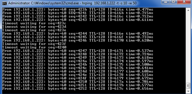
It did seem to work well however upon using HRping when switching on and off the RX/TX lines there was some packet loss. I played around with it a bit and found that if you connected the RX+ to ground first, waited a few milliseconds and then connected RX- to the peak detector, then there wasn’t any packet loss. In order to do this we need more pins so we’ll upgrade to the ATtiny84.
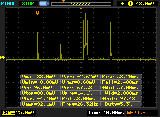
Now we can start to improve our power consumption, I reduced the clock to 128KHz by using the internal 128KHz oscillator, instead of using delays we’ll use the watchdog sleep and enable pull ups. I connected a 100 ohm resistor and measured the voltage drop on that using my scope. I tested the ATtiny84 by itself and you can see the spikes were it’s executing code and there are some spikes going up to 0.8mA and all up we’ll say it’s for 10ms. Download INCT_v0.3
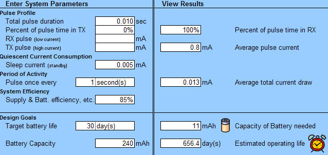
If we did the ADC reading every second, the battery should last us almost 2 years.
When I added the 74HC4066 and connected it up to the RX/TX lines I noticed that the current spiked up to 0.2mA. After a bit of testing, it appears that it jumps to 0.2mA when the control line of RX+ to GND is enabled even when the control line of RX- to the peak detector is low. I can only assume this is caused by leakage somewhere in the analog switch however if you connect the RX- to the peak detector directly and have the analog switch only do the grounding then that seems to work, it just means we’ll need need 2 peak detectors and use 2 pins for the ADC.
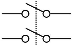
For the 330 ohm resistor to connect to the RX/TX lines at the moment it’s just on a SPST switch but I need a DPST switch (double pole single throw) which allows two sets of wires to connect to each other separately. However after searching for a small DPST switch, I only was able to find large switches and ones that cost $2+ each, we could use the analog switch to do this instead perhaps.
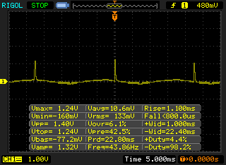
Also I found that when checking the network of my laptop, I received a strange signal instead of the usual one I was expecting. There are peaks every 23ms and upon zooming in, it does look like a normal signal. I thought that this might be some power saving option on the network card and after turning off the “Energy Efficient Ethernet” option, the signal returned to normal. This brings up another problem, how will we detect with this?
I’ll need to leave all of this for the next part and continue with more testing.


