Following on from Part 1, we looked at building our In-line Network Cable Tracer and I was hoping to do a PCB for it however when I connect another INCT to the network cable at the other end, it sometimes didn’t work.
I started playing around with the circuit, removing the capacitor, adding a resistor between AIN1 and AIN0 and tried to use an opamp with it too – none worked well.
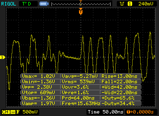
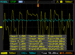
But now that I have an oscilloscope I can actually check how the signal looks, something that the multimeter can’t ever help us with (I removed my earth pin on the oscilloscope plug to make sure nothing blows up). We can see that there is just about -1V and +1V to give 2.38V peak to peak.
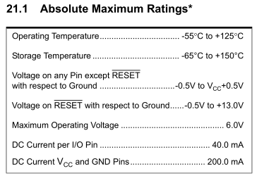
Previously with the ATtiny, we had one of the receive wires going to ground and another going to PB1, so this was technically swinging to -1V respect to ground but technically this is out of the specs of the absolute maximum ratings.
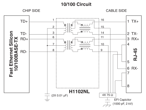
Somehow I got on to the subject of RJ45 sockets / isolation and found that with ethernet ports you need to use isolation – either using a chip (e.g H325-32121) which is how most routers do it or there are magjacks which have the transformer built in. One of the reasons for using transformers on each of the ethernet cable is to reduce the ground offset.
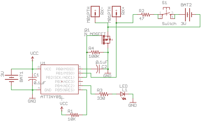
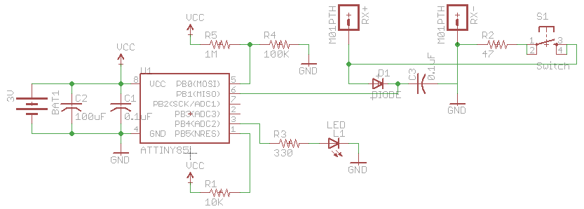
Isolation transformers are a bit pricey and do we really need an isolation transformer? I don’t think we do as we are just passing the ethernet signal through (I may need to look into TVS diodes). My next thought was perhaps I could use an opt-isolator which it did seem to work however when sending any data it didn’t work, I guess you shouldn’t draw any current. After some testing, I went with a diode and a 1M resistor which seemed to work quite well however the voltage was bouncing around a bit.
The simple fix was to add a 0.1uF capacitor and now we have a stable voltage (blue line). I took out the resistor but found that when I applied the 47ohm resistor to the RX+/- wires that it didn’t have an immediate affect, re-adding the 1M resistor sorted it out.
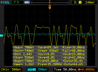
And here’s how the signal looks like with the 47 ohm resistor applied. You can see the signal is reduced and voltage on the capacitor has also been reduced to about 100mV. (One day when I connected a 20m wire instead of the 0.5m wire I was using, the signal degraded but not as much as the 47 ohm resistor, but I can’t seem to replicate this any more).
Because the signal is reduced when the resistor is applied, we can still use the ATtiny’s analog comparator and just use a resistor divider on the other input of the comparator, I found using a 1M with 100k resistor is good enough (272mV at 3V or 226mV at 2.5V) to be higher than when the 47 ohm resistor is applied.
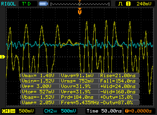
Now when I tried running two of these, it works well however sometimes it doesn’t work until you put the 47 ohm resistor on the other end of the RX wire. Above is a picture of when it doesn’t work, it changes the signal a little but not by enough. I found that when the RX didn’t work for one direction, the TX wires did work, this is because one end transmits while the other receives which means it wouldn’t affect the other side as the flow is going the other way around.
The solution would be when the button is pressed, we will need to connect the resistor to the RX lines and another resistor to the TX lines which means that the other end will need to switch between the RX and TX lines to detect this. The way we could do the above switching between the RX and TX is by using an analog switch but we’ll leave that and more testing for the next part.


