After seeing a few solar garden lights as a quick project I decided to make my own version using the ATtiny13A so it can be low cost but have decent functionality. I didn’t an RGB LED so I went with red, green and yellow LEDs and in terms of the solar panel I have a 4V 50mA one.
(sneak peak of the end result)
My first initial thought was to use a Lipoly battery to power everything, use a diode with the solar panel to recharge the battery with an LDO to 3.7-3.9V if needed. My main concern is leaving the Lipoly outside and it heating up quite a lot so I’ve decided to go with AA batteries.
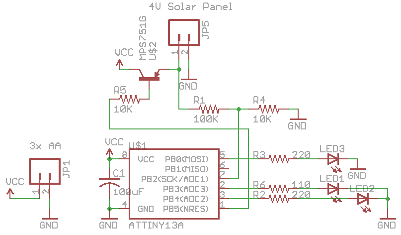
After a few iterations of the design, I went with 3x AA batteries to be recharged and the charging will be switched on using a PNP transistor, I’m going for 1.4V per AA battery. Originally I wanted to go with a N or P mosfet however since the Vds would be less than 1V so it wouldn’t be able to switch on. One unintended feature of the PNP design in this case is that it’ll automatically charge up the 3x AA batteries if they are 0.6V lower than the solar panel.
_delay_ms(50);
if (ledPulseCycle == 0) {
	ledPulseDuty++;
	if (ledPulseDuty >= 100) {
		ledPulseCycle = 1;
		ledEndNow = true; // End when led finishes diming
	}
}
else {
	ledPulseDuty--;
	if (ledPulseDuty == 0) {
		ledPulseCycle = 0;
	}
}
...
ISR(TIM0_OVF_vect) { // Used for pulsing LEDs
	if (pulseCounter >= ledPulseDuty) {
		PORTB |= (1<<ledToPulse);
	}
	else {
		PORTB &= ~(1<<ledToPulse);
	}

	pulseCounter++;
	if (pulseCounter == 100) {
		pulseCounter = 0;
	}
}
As the ATtiny13A only has 1 timer so we can use software PWM to control the LEDs. We’re running at 1MHz with a prescaler of 1 which allows us to have an overflow of once every 256uS. I found that having a counter to 100 with it switching the LED on or off depending on the duty cycle selected worked well, we then change the duty cycle after we delay for a bit and by changing the delay time we can say how fast or slow to pulse.
// Check if solar panel is producing 3.8V+
cbi(TIMSK0, TOIE0); // Turn off Timer0 interrupt
sbi(ADCSRA, ADEN); // Enable ADC conversions
PORTB |= (1<<chargePNP); // Stop the charging briefly to read the solar panel voltage only
analog_read(solarPanelADC); // Ignore first reading
int solarReading = analog_read(solarPanelADC);
cbi(ADCSRA, ADEN); // Disable ADC conversions
sbi(TIMSK0, TOIE0); // Turn on Timer0 interrupt

if (solarReading > 20) { // More than 0.25V on solar panel?
	ledFunction = -1; // Switch off LEDs
	PORTB &= ~(1<<redLED);
	PORTB &= ~(1<<greenLED);
	PORTB &= ~(1<<yellowLED);
	TCNT0 = 0; // Set Timer0 to 0
	TCCR0B = 0; // Turn Timer0 off
	nextADCcheck = 9; // Check ADC again after sleep

	if (solarReading > 310) { // Around 3.8V+, start charging
		PORTB &= ~(1<<chargePNP); // Turn on
		watchdog_sleep(T500MS); // Sleep less to monitor solar voltage more
	}
	else { // Between 0.25V to 3.8V, do nothing
		watchdog_sleep(T2S); // Sleep more
	}
}
else { // Less than 0.25V, then switch on LEDs
	PORTB |= (1<<chargePNP); // Turn off
	if (ledFunction == -1) {
		ledDelay = 12500; // 50ms
		ledFunction = 0; // Which function to load first
		ledFunctionInit = true;
	}
	nextADCcheck = 0;
}
To detect the solar panel voltage, we use a 100K / 10K divider, once we hit 3.8V we switch on the PNP and then check again in 500ms in case something blocks the solar panel because otherwise it will drain some current from our batteries. One thing to note is that we switch off the PNP before running the ADC, as we just want to read the solar panel voltage and not batteries current voltage. If we see 0.25V or less, we start turn on the LEDs.
if (ledFunction == 0 || ledFunction == 1 || ledFunction == 2) {
	...
	if (ledFunction == 0) { // Pulse Red LED
		ledToPulse = redLED;
		pulsing(ledDelay);
	}
	...
}
else if (ledFunction == 3) { // Blink all LEDs one after the other
	ledTempDelay = ledDelay * 4; // Make the delay a bit longer
	for (uint8_t x = 1; x < 10; x++) {
		PORTB |= (1<<redLED);
		delay_loop(x);
		PORTB &= ~(1<<redLED);
		delay_loop(x);
		...
	}
	ledEndNow = true;
}

if (ledEndNow == true) { // Finished LED function
	ledFunction++; // Proceed to next function
	ledFunctionInit = true;
	ledEndNow = false;
	...
	// End of functions, speed up the delay time
	if (ledFunction >= ledFunctionEnd) {
		ledFunction = 0;
		if (ledDelay == 500) { // Reset delay to 50ms
			ledDelay = 12500;
		}
		ledDelay = ledDelay - 3000;
	}
}
Now to the fun part, we can make our LEDs to anything we like, I have a function to pulse all LEDs individually and another one to blink them, then once the functions are finished, we speed things up a few more times. As we are using delays and we speed things up, we can’t use _delay_ms(x), instead we use _delay_loop_2(x) which we don’t have to give a fixed number at compile time.
https://www.youtube.com/watch?v=ueRYOK8W8no
Here’s how it looks in the dark, I’m using a clear container which once contained spices. Going back to the 3x AA batteries design, it seemed like the solar panel was receive 4.2V at about 50mA however I only saw about 5-10mA going into the AA batteries though they are 1-3 years old and usually lose charge after a few days. I left it charging for the afternoon and ran the LEDs, after 10 minutes the voltage had dropped from 3.6V to 2.8V so using AA batteries in this case wasn’t going to work out.
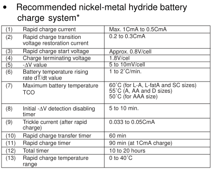
It appears that with NiMH batteries that you need a constant current source whilst keeping the maximum voltage of each battery down to 1.8V, so a constant voltage of 1.4V like I intended won’t work. We can set up an LM317 with constant current however after testing we’d need a 6V solar panel for each individual AA battery.
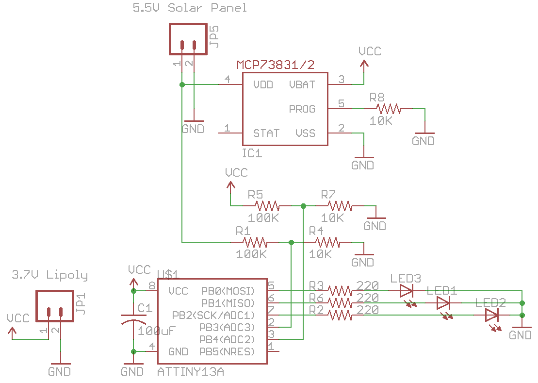
So I’m back to square one, the Lipoly battery really seems like the best option and my spare 200mAh one could last at about 1 day with an 8mA constant load. If I were to increase the solar panel to 5 – 6V, I could use the MCP73831 Lipoly charger chip and not worry about over charging the Lipoly. I’ve tested to make sure that if the charger isn’t receiving the required 4.5V+ voltage that it won’t draw anything from the battery.
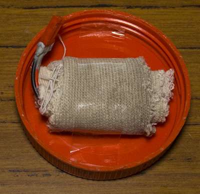
However the problem of heat when in sunlight remains, according to some sources, you shouldn’t charge batteries when they are 50C+. After testing different ways to protect the battery from the sunlight, I found that wrapping it up in a few layers of clothes and putting up near the lid seemed to do the trick, it gets to 42-45C.
I sourced the cheapest RGB LED I could find from my supplier which was a Cree for $0.94 and the brightness was good improvement compared to the red, yellow, green LEDs I was used, as you can see the sneak peak video at the start. ATtiny13_Solar_LED
I’m just waiting on a 5.5V solar panel before I can complete this project. I wonder what other features I could add, now that I have a RGB LED I could make other colours pulse and maybe have these lights communicate with the nRF for a mini light show?


