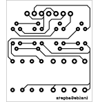
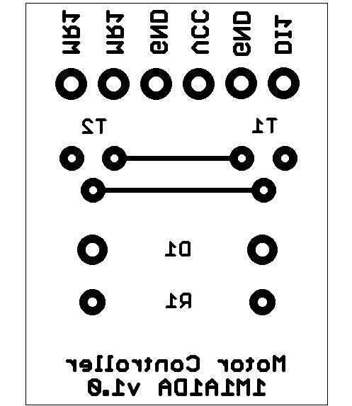
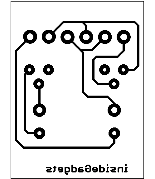
Following on from Part 3, our motor controller has been successfully built and tested, now it’s time to release the parts used, where to place them, etc so you can build your own. I’ve actually taken consideration to what I said in Part 3 and have re-designed the Motor Controller to have the components and lines to be spaced out a bit more however I’ve changed the lines back to 0.254mm wide. You have the option of both v1.0 or v1.1 boards, I recommend v1.1 even though it is a little bigger.
Motor Controller – Bi-directional (2)
Parts required
T1 & T5 – MPS751G Transistor (2)
T2, T3, T4, T6, T7, T8 – BC637 Transistor (6)
R1 & R3 – 39Ohm Resistor 1W (2)
R2 & R4 – 390Ohm Resistor 1/4W (2)
D1, D2, D3, D4 – 1N4004G Diode 400V 1A (4)
7 pin header (female or male, your choice)
Motor Controller 1M1A2DA v1.1 (Recommended)
36mm x 30mm
Motor Controller 1M1A2DA v1.0 (smaller PCB but harder to solder components)
35mm x 26mm
Above are the 600dpi images that I’ve used to make my PCB. Just follow Part 3 of the Building a Motor Controller tutorial and you’ll be right :). 1M1A2DA stands for 1 motor, 1 amp, 2 directions (bi-dir) and Ardunio compatible.
I might think about selling these so some features of this motor controller is below (which you should already know if you read my previous posts!)
Features
– Separate motor power source
– Supports 1 motor turning in both directions
– Up to 1 Amp current
– BackEMF protection
– Low voltage drop
– Easy to use circuit
Specifications
Logic inputs: 2
Logic voltage: 5 Volts
Maximum logic current used: 20mA
Minimum motor input voltage: 6 Volts
Maximum motor input voltage: 12 Volts
Maximum motor input current: 1 Amp
Maximum motor input current consumed on circuit: 100mA @ 1 Amp
Operating temperature: 0 – 40C
Edit: 1 directional motor controller has been created as below.
Motor Controller – Directional (1)
Edit 27/10/10: I just realised that you don’t need half the components on this board! This is what happens when you scale back your initial design without checking each components purpose. v1.1 has been released.
Parts required
T1, T2 – BC637 Transistor (2)
R1 – 390Ohm Resistor 1/4W (1)
D1 – 1N4004G Diode 400V 1A (1)
6 pin header (female or male, your choice)
Motor Controller 1M1A1DA v1.1
24mm x 18mm
Features
– Separate motor power source
– Supports 1 motor turning in one direction
– Up to 1 Amp current
– BackEMF protection
– Low voltage drop
– Easy to use circuit
Specifications
Logic inputs: 1
Logic voltage: 5 Volts
Maximum logic current used: 20mA
Minimum motor input voltage: 6 Volts
Maximum motor input voltage: 12 Volts
Maximum motor input current: 1 Amp
Maximum motor input current consumed on circuit: 100mA @ 1 Amp
Operating temperature: 0 – 40C

This work is licensed under a Creative Commons Attribution-NonCommercial-NoDerivs 3.0 Unported License.


