Last week we looked at SoftI2C so we could use an I2C EEPROM on any of our AVR’s pins and now it’s time to apply that to the Standalone Temperature Logger as the internal EEPROM of 512 bytes is a bit limiting.
Identifying the pins to apply I2C to
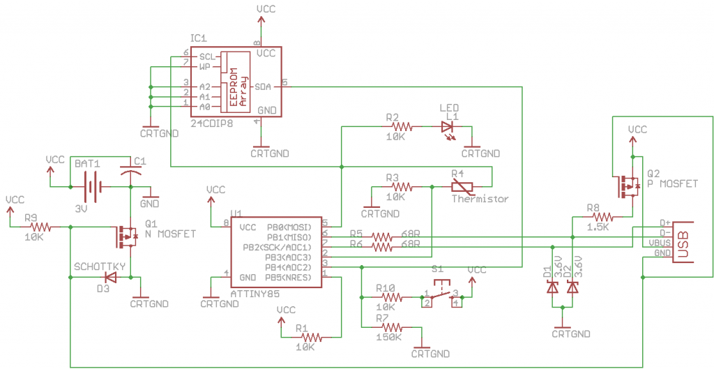
The first step is to identify which 2 pins we can use, we rule out the USB pins PB1 and PB2. After some testing I found PB0 for the clock and PB4 for the data seem to work well. In SoftI2C the clock is only ever an output, we have a line like that already, the LED one PB0. The data line changes between an input with pull-up resistor and output, we also have a 100k pull-down to ground which you’d think should affect the pull up but we’ll see why it shouldn’t.
The reason it shouldn’t is because the internal pull-up resistor is between 20K and 50K per the datasheet page 167. Since it’s a low value resistor compared to our 100k resistor it makes a desirable voltage divider.
We need to find out the voltage that our EEPROM detects a high signal, from an Atmel EEPROM datasheet it shows it being Vcc x 0.7 which gives 2.1 volts.
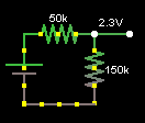
Let’s see the difference between a 100k pull down and a 10k pull down with the 20k min or 50k max pull-up values on the ATtiny85. The worst case scenario is 50k pull-up with 100k pull-down to give 2 volts which is just below the 2.1 volts needed.
We learnt before that the highest resistor value we can use is 900k and as the 100k resistor is barely cutting it at the worst case scenario, we’ll increase our pull-down resistor to 150k.
Button can now cause high current to flow and disable pin change interrupt
An issue is brought up when using the data line, what if the data line is in the output (sink) mode which does happen for a few microseconds and the button was pressed? Current would flow through to the data line in the ATtiny85; we can stop this by placing a 10k resistor between the button and 100k resistor.
Now we just need to verify this 10k resistor and 100k resistor divider will still provide a high voltage like we did before for the EEPROM. Minimum high needed is 1.8 volts (0.6 x Vcc), we can see the voltage divider gives us 2.8 volts so we’re fine.
void SoftI2cMasterInit(void) {
  cbi(GIMSK,PCIE); // Disable pin change interrupt as SoftI2C will trigger it
  DDRB |= (1<<TWI_SDA_PIN);
  ...
}
Since we use PB4 which our button is on, we need to disable the pin change interrupt because this interrupt still occurs even if you use the pin as an output and switch between on and off.
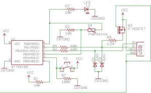
Here is the updated schematic.
Writing at 1MHz with I2C
All we need to do is replace the existing EEPROM code which write the temperature to happen on the I2C EEPROM. I added in a small delay before we read the thermistor for everything to stabilise. Since we are only writing when at 1MHz I changed the soft_i2c_eeprom_write_byte function to be 650us (.650 x 16.5 = 10.7ms) due to the F_CPU being set to 16.5MHz.
PORTB |= (1<<ledPin); // Turn on LED which also turns on the thermistor
_delay_us(50); // Wait a little while before reading thermistor
int tempValue = (int) thermistorTemp(analogRead(thermistorPin));
...
// Write to EEPROM
if (dataCount < 512) {
  SoftI2cMasterInit();
  soft_i2c_eeprom_write_byte(EEPROM_ADDR, dataCount, tempStore);
  dataCount++;
  if (dataCount < 512) {
    soft_i2c_eeprom_write_byte(EEPROM_ADDR, dataCount, 0);
  }
  SoftI2cMasterDeInit();
}
It all appears to be functioning correctly.
Reading at 16.5MHz with I2C
int sendnextDigit(int eepromAddress) {
  uchar digit;
  int value = soft_i2c_eeprom_read_byte(EEPROM_ADDR, eepromAddress);
  ...
}
Now it’s time to read the data from the I2C EEPROM and once again the code change is very simple one.
I did notice that at 16.5MHz that things didn’t look quite right. It looks like our clock low (yellow) isn’t long enough and the same goes for our acknowledgement at the end of each byte sent/received.
// Write a byte to I2C
bool SoftI2cMasterWrite(uint8_t data) {
    ...
    _delay_us(I2C_DELAY_USEC); // Extra delay (needed when 16.5MHz)
    PORTB |= (1<<TWI_SCL_PIN);
    _delay_us(I2C_DELAY_USEC);
    PORTB &= ~(1<<TWI_SCL_PIN);
  }
  _delay_us(I2C_DELAY_USEC); // Extra delay (needed when 16.5MHz)
  // get Ack or Nak
  DDRB &= ~(1<<TWI_SDA_PIN);
  _delay_us(1); // Extra delay (needed when 16.5MHz)
  // Enable pullup
  PORTB |= (1<<TWI_SDA_PIN);
  PORTB |= (1<<TWI_SCL_PIN);
  _delay_us(I2C_DELAY_USEC); // Extra delay (needed when 16.5MHz)
  uint8_t rtn = bit_is_set(PINB, TWI_SDA_PIN);
  PORTB &= ~(1<<TWI_SCL_PIN);
  PORTB &= ~(1<<TWI_SDA_PIN);
  DDRB |= (1<<TWI_SDA_PIN);
  _delay_us(I2C_DELAY_USEC); // Extra delay (needed when 16.5MHz)
  return rtn == 0;
}
What I did was add some delays in SoftI2cMasterWrite and SoftI2cMasterRead.
Which after some testing now seems to have corrected the issue, everything looks much nicer.
Automatically check for EEPROM size
This section should probably be it’s own post as it’s a little large. As we now have allowed the ability to use an external EEPROM this means that we can use EEPROMs of all sizes so we’ll need to know which one we are using. I’ve made a function which can do this work for us instead of having the user have to program it using the button like they do with the delay time.
I’ve decided against running this function every time before starting logging because it’ll write to the EEPROM too many times which can be avoided, so instead I’ve decided to run this function when the battery is inserted (or when the USB in inserted with no battery present) which seems logical as you should only change the EEPROM when the power is off.
int eepromMemsize = -1; // No EEPROM found by default

#define eeprom1Kbit 127
...
#define eeprom512Kbit 65535

#define eepromA0 (1<<1) // 00000010
#define eepromA1 (1<<2) // 00000100
#define eepromA2 (1<<3) // 00001000

// Maps the EEPROM last writeable location
uint16_t eepromMap[10] = {
  eeprom1Kbit,
  ...
  eeprom512Kbit,
};
We first set up our variables – eepromMemsize is the variable which keeps track of the EEPROM size. eeprom1Kit, etc maps the last writeable address of a 1Kbit EEPROM and eepromMap maps the writeable addresses so we can reference them easily.
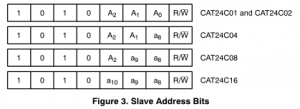
A technique that 8bit EEPROMs use if want use an address higher than 255 is they use the A0-A2 for the higher bits and this is what our variable eepromA0-A2 is for. The downside is that if some or all of the A0-A2 is used it means the ability to use multiple EEPROMs decreases.
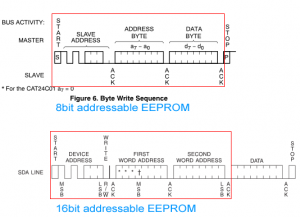
The first problem with using different EEPROMs is finding out if they use 8bit or 16bit addresses, why you ask?
It’s because a read or write to a 16bit address look like a write to an 8bit EEPROM (I released this when my tests were failing).
// Test what EEPROM which is inserted by writing and reading the last memory location of 1Kbit, 2Kbit, etc
// with different values, if the values don't match then we know the EEPROM memory limit has been reached
void eepromSizetest(void) {

  int i = 9; // Start off checking the highest EEPROM (512Kbit)

  // Check if it's an EEPROM with an 8bit address (if we don't check for this and run a write made for a 16bit
  // addressable chip on an 8bit chip, it will write the second byte of the address to the first byte of the address)
  SoftI2cMasterInit();
  int saveByte = soft_i2c_eeprom_read_minimal(EEPROM_ADDR, eepromMap[0]);
  soft_i2c_eeprom_write_minimal(EEPROM_ADDR, eepromMap[0], 1);
  int readNumber = soft_i2c_eeprom_read_minimal(EEPROM_ADDR, eepromMap[0]);
  soft_i2c_eeprom_write_minimal(EEPROM_ADDR, eepromMap[0], saveByte);
  SoftI2cMasterDeInit();

  if (readNumber == 1) {
    i = 4; // Detected 8bit addressable EEPROM, start off at highest 8bit address EEPROM (16Kbit)
  }
We test for presence of an 8bit addressable EEPROM, the variable i is used to map to the eepromMap. We read the byte which we will write to so that we can preserve the data that’s already there, then we write 1 to the address and see if we can read 1 back. If we can then it’s an 8bit EEPROM and we’ll start our tests on the highest 8bit addressable EEPROM available – 16Kbit.
// Start checking for EEPROM size
while (i > 0) {
  SoftI2cMasterInit();

  // Save the data that is at the location we will write to
  int saveByte = soft_i2c_eeprom_read_minimal(EEPROM_ADDR, eepromMap[i]);
  int saveByte2 = soft_i2c_eeprom_read_minimal(EEPROM_ADDR, eepromMap[i-1]);

  // Write/read test
  soft_i2c_eeprom_write_minimal(EEPROM_ADDR, eepromMap[i], i);
  soft_i2c_eeprom_write_minimal(EEPROM_ADDR, eepromMap[i-1], i-1);
  int readNumber = soft_i2c_eeprom_read_minimal(EEPROM_ADDR, eepromMap[i]);

  // Restore the data that was originally at the location
  soft_i2c_eeprom_write_minimal(EEPROM_ADDR, eepromMap[i], saveByte);
  soft_i2c_eeprom_write_minimal(EEPROM_ADDR, eepromMap[i-1], saveByte2);

  // If we can still read the first value that we wrote to a higher location, we found the EEPROM size
  if (readNumber == i) {
    eepromMemsize = i;
    break;
  }
  SoftI2cMasterDeInit();
  i--;
}

// Try the smallest EEPROM size by itself if no other EEPROM size was found
if (eepromMemsize == -1) {
  SoftI2cMasterInit();
  int saveByte = soft_i2c_eeprom_read_minimal(EEPROM_ADDR, eepromMap[0]);
  soft_i2c_eeprom_write_minimal(EEPROM_ADDR, eepromMap[0], 1);
  int readNumber = soft_i2c_eeprom_read_minimal(EEPROM_ADDR, eepromMap[0]);
  soft_i2c_eeprom_write_minimal(EEPROM_ADDR, eepromMap[0], saveByte);

  if (readNumber == 1) {
    SoftI2cMasterDeInit();
    eepromMemsize = 0;
  }
}
SoftI2cMasterDeInit();
Now what happens is that we check from the highest memory location to the lowest and check the if value we wrote matches what we expect. We need to write to 2 locations at a time to get an accurate result otherwise if we don’t and the EEPROM is smaller we will think it’s actually a larger EEPROM than it is.
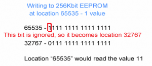
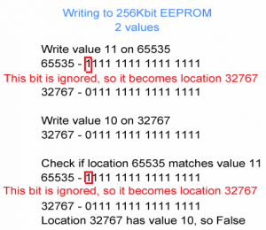
For example, assume we have a 256Kbit EEPROM (32767) and we write 11 to location 65535, the EEPROM would ignore the higher bit. We attempt to read location 65535 which would really read location 32767 instead and we would receive the number 11 so we would assume it’s 512Kbit when it’s really not.
Now if we write 11 to location 65535 and 10 to location 32767, then read location 65535 which really reads 32767 we would receive the number 10 so we know it’s not a 512Kit EEPROM. We repeat this for locations 32767 and 16383, 16383 and 8191, etc.
// Read EEPROM size if battery was inserted or EEPROM not found
if (eepromMemsize == -1) {
  _delay_ms(62); // Wait 1 second (62 x 16.5MHz = ~1)
  eepromSizetest();
  if (eepromMemsize == -1) { // No EEPROM found
    blinkLed(1, T2S, SKIPLEDOFFDELAY);
  }
  else {
    blinkLed(eepromMemsize+1, T500MS, 0);
  }
}
If the ATtiny85 powered up (by USB or battery) or there was no EEPROM found, we delay for 1 second before calling the eepromSizetest function. The reason I delay 1 second is because I found in my testing that the EEPROM would become corrupt when I would plug in the power cable which means that it might be getting reset one or more times when it’s writing to the EEPROM which takes at least 10ms each time. I think it’s a good idea as when you insert a battery sometimes it’s a bit fiddly so you could have the potential of disconnecting power after a few milliseconds. If the EEPROM is detected the LED will blink a certain amount of times, e.g. blink 7 times for 64Kbit EEPROM, 8 times for 128Kbit, etc.
Update a 10k resistor to 1% and move delay time interval to an array
One thing that I didn’t do but should have done long ago is update the 10k resistor using in the thermistor divider to a 1% part for a bit more accuracy and it only costs us 6 cents more than 5% resistor.
// Maps the button presses to the delay time
int delayTimemap[11] = {
  7, // 28 seconds
  15, // 60 seconds
  (5 * 15), // 5 minutes
  (10 * 15), // 10 minutes
  (15 * 15),
  (30 * 15),
  (60 * 15), // 1 hour
  (2 * 60 * 15), // 2 hours
  (4 * 60 * 15),
  (8 * 60 * 15),
  (12 * 60 * 15),
  (24 * 60 * 15), // 24 hours
};
Another thing is I’ve updated the delay time intervals, put them in an array for easy referencing and have just added a 28 second delay time since have a lot more space on an external EEPROM to write to.
Updated power usage
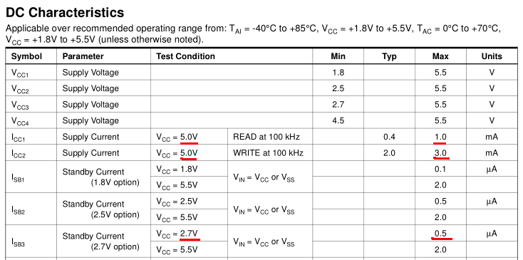
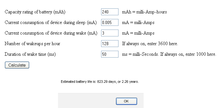
It’s time to re-evaluate the power usage with the I2C EEPROM. From the datasheet it says the standby current at 2.7V is 0.5uA and reading/writing is 1mA to 3mA max at 5 volts. From my testing I noticed that the total current draws stays at 4.8uA when everything is sleeping and without the EEPROM it’s 4.4uA, not too bad at all.
From my testing I didn’t measure 3mA when writing (I didn’t notice much change from 0.3mA) but then again the write cycle only took 34 ms so my multimeter probably isn’t equipped to detect that change fast enough.
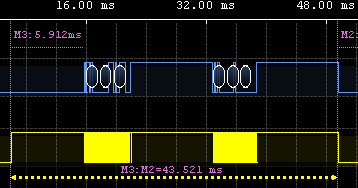
The total time that the AVR is awake when logging the temperature is now 43 ms which we’ll round up to 50 ms.
So let’s take the worst case scenario as we do and say we draw 3mA for 50 ms (which isn’t true) at the lowest logging interval (28 seconds), the battery life is 2.26 years.
Conclusion
After testing with 2 different EEPROMs it all seems to work correctly. I will be making the PCB and will release the SATL v3.0 by next week. Here is the SATL_v3.0 source.









I’d like to make this temp logger and I would make this rather than the smaller one. I could make the board and get the parts but thats a lot of messing about. Is anybody making a kit of either one that you are aware of ? Do you have any plans to make a kit? I’d take one at least ! Nah just kidding Put me down for 5 .
Thanks for your interest :). I think this project is now at the point where it’s good enough to make a kit out of it, so yes I’m planning on making a kit once my PCB prototype tests out ok (which should be by next week) and then I’ll order 10 boards which may take 2-3 weeks to arrive.
So hopefully I should have something ready in about a months time if all goes to plan.
Hi. Interesting project. Is there an inexpensive way to make a programmer for the micro-controller chip? I would like to use the voltage recorder version of the project with the EEPROM. I am interested in the circuit board. Will you be making an adaptable version of the board that can be made into the temperature logger or the voltage logger? Thank you!
Steve
Hi Steve,
Yes there are inexpensive ways to make a programmer:
If you have a serial port – http://diy4fun.blogspot.com.au/2009/01/simple-serial-programmer-for-avr.html
If you have an ATtiny – http://www.simpleavr.com/avr/vusbtiny
But the cheapest/easiest is really just to buy a USBASP from Ebay for about $5
A good idea about the temperature / voltage logger on one board, I will see if I can make this idea be final version of the whole product.