In my Adding EEPROM to the SATL post I briefly spoke about my multimeter not being about to measure the current of the SATL when it was writing to the EEPROM, mostly due to the fact that it happens so quickly in under 50ms. I decided that solving this problem would be my next project to work on.
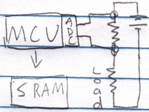
My thoughts are to have an MCU sampling the ADC, use a resistor’s voltage drop to calculate the current then write the result to SRAM (instead of an EEPROM as it would take 10ms for each write). If possible, I would like it to also be powered by a 3V battery.
The maximum ADC samples per second that the ATtiny85 can do is 15,384 (15KSPS) at 200KHz which when compared to chips designed specifically for ADC that run at 200KSPS doesn’t seem like a lot, but in our case it’s a lot. The reason is that if we had a 64Kbit SRAM, it would only be able to store 8,192 samples which is just over half of the 15K samples per second, it would only record 0.5 seconds before running out of space. For a 256Kbit SRAM it would be 2 seconds.
Design attempt 1
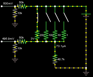
Naturally I start up a circuit simulator and play around with different value resistors, resistors to simulate the load and find the voltage drops. Eventually I came up with a design that should be able to measure 10uA to 10mA using 3 resistors, 3 mosfets (for switching each resistor on/off) and use 2 ADCs.
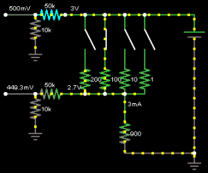
In the picture above – 500mV would go to ADC1, 495.9mV goes to ADC2 and 40.7k is the load. The first thing about this design is that it’s very inefficient and if a load jumps from say 500uA to 3mA there is no quick way to change the voltage drop resistor. The way it works is each resistor is a different value and corresponds to a different current range, 200 ohms covers 0-100uA, 100 ohms for 100uA-1mA and 10 ohms for 1-10 mA (Ignore the 1 ohm resistor).
Let’s see what happens if the the current jumps from 500uA to 3mA. The voltage drop on the 100 ohm resistor becomes 0.3V which means our load only gets 2.7V.
Design attempt 2
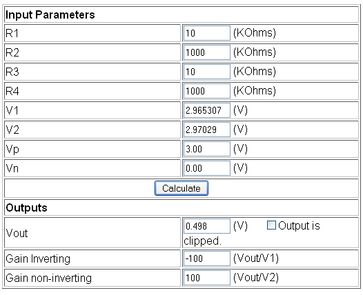
I had hear of op-amps before but never really looked into them. I watched an op-amp video by Sparkfun, I played around with an op-amp calculator and came up with something that I should be able to use in this project. There are many ways that you can use an op-amp and I’ll be using it as an differential amplifier.
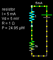
Let’s start with a 1 ohm resistor, it generates a low voltage drop and it’s basically a 1 to 1 ratio with the current. If the current draw of our load is 5mA, the voltage drop is 5mV.
We’ll be using a 1.1V reference voltage for the ADC which means we can only sense a difference in approximately 1mV increment. We would only see a change 5 times (1mA we see a change, 2mA another change, etc), it isn’t very good. If we can somehow boost the voltage drop by 100 times, a 1mA current draw / 1mV voltage drop would result in 100mV output. This means we could measure in 10uA increments (1,000uA / 100mV = 10uA/mV), that seems much better. But how do we make 100mV output from a 1mV voltage drop?
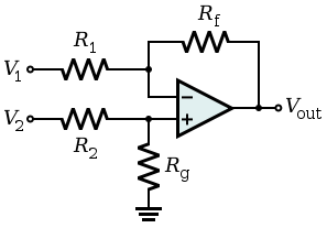
This is where the op-amp comes in. An op-amp which is run as a differential amplifier can measure the voltage difference on its two input pins (V1 + V2) and output the change (Vout) based on the amplification ratio we choose by changing 2 resistors, R1 and Rf. To achieve 100x amplification, we use R1 as 10K (normally a good value by default) and 1M as Rf which gives 1000K/10K = 100. V1 is where we feed in the voltage after the 1 ohm resistor and V2 is the reference voltage. Because both inputs are from the same voltage source, this means that V1 has to match V2 if there is no load so we need to use a 10K for R2 and 1M for Rg like we did for R1 and Rft.
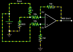
The above example shows what would happen with a 5mA (technically 4.99mA) load. We can calculate V2 our reference voltage by using the resistor divider formula assuming we have 3 volts in: V2 = 3V x (1000K/(10K+1000K)) which gives 2.97029V. Now we apply the same formula for V1 however with a 4.99mA load over the 1 ohm resistor gives us 4.99mV drop which we minus from the 2.97029V which would give us 2.965307V. The op-amp amplifies the difference between V1 and V2 by 100x and the output reads 498.9mV. In theory this should all work. The maximum current we can measure is 10mA otherwise we would exceed our 1.1V reference voltage.
Input Offset Voltage
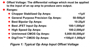
I was checking different op-amps data sheets to see if there was anything I needed to be concerned about and there was something called the “Input Offset Voltage” which kept on appearing and I wasn’t sure of it.
It turns out that the op-amps aren’t always precise because the internals for both inputs (V1/V2) can’t always be 100% matched. I found a tutorial from Analog Devices explaining it, the first page is all you need to read to get a sense of it.
The first op-amp I looked at was the LM358 which has an input offset voltage of 3mV max, this means that if our V1 was 2.967V (V2 as 2.970V) the op-amp would display the difference as being 0mV which isn’t what we want. It would mean that more than 3mA would need to pass through our load before the op-amp registered anything.
After looking around I found a TI OPA333 which has an low offset voltage of 10uV max and can run at 1.8V to 5.5V, has a quiescent current on 17uA and is priced fairly well. This means that more than 10uA of current would need to pass through our load before the op-amp registered anything and I’m happy with that. For the next part, I’ll need to order this op-amp, give it a test and hope this theory works out.
