I recently bought a Rigol DS1052E and have been playing around with the different functionality it has. Eventually I came to the point that I’d like to see what frequency does to various components and wanted to build a voltage controller oscillator (VCO).
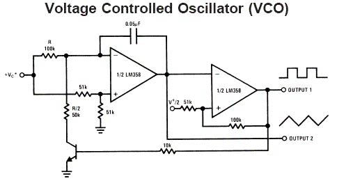
By using 2 opamps and some passive components we can build a VCO as shown above. But I wanted to make one that was simpler so I looked at the ATtiny25.
ATtiny25 Clockout as VCO
The ATtiny25 has a clock out fuse bit which when enabled, outputs the system clock of the ATtiny but the downside is that you can only run on the internal oscillators when you enable that option. As we do with the SATVL, we can use the 16MHz PLL for our system clock and by modifying the OSCCAL value we can underclock and overclock our ATtiny25 – this is the one VCO method we could use. Download ATtiny25_Clockout
Underclocking and overclocking the ATtiny25 – 10MHz minimum to 33MHz maximum.
ATtiny25 Timer1 as VCO
But what if we don’t want to overclock our ATtiny25? I didn’t know but you can actually use the PLL as a clock source for Timer1 and we can keep our system clock at 1MHz.
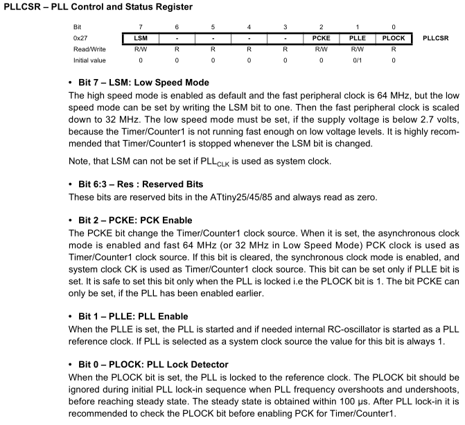
// PLL Enable
sbi(PLLCSR, PLLE);
_delay_ms(10);

// PCK Enable
sbi(PLLCSR, PCKE);
Firstly we enable the PLL clock, we can either wait for the PLL lock detector or can just wait a few milliseconds and then enable PCK to feed into timer1. There is an option for LSM which reduces the PLL clock from 64MHz to 32MHz.
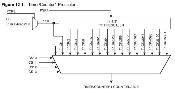
OCR1A = 0;
OCR1C = 0;
sbi(TCCR1, COM1A0);
sbi(TCCR1, CTC1);
sbi(TCCR1, CS10);
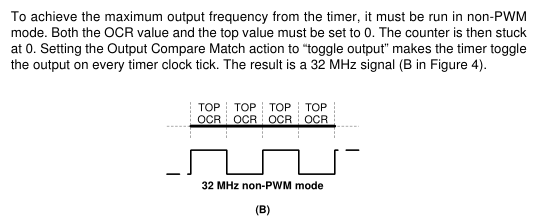
We can generate a 32MHz clock by setting the OCR1A/1C (compare on matches) to 0, turn on COM1A0 to toggle the output pin PB1 on compare match, turn on CTC1 to reset the timer to 0 when it matches OCR1C and set the clock prescaler to 1. I found this from the Using the AVR’s High-speed PWM PDF – page 3.
while(1) {
  int setting = adcRead(3);
  OCR1A = (setting / 8); // Compare to
  OCR1C = ((setting / 8) * 2); // Set top
  _delay_ms(200);
}
By changing OCR1A/1C we can generate different frequency, we just need to keep OCR1C double the value of OCR1A to make sure we keep a nice square wave and use a 10K pot with the ADC to adjust values. Download ATtiny25_Basic_VCO
We have a range of 128KHz to 32MHz, at the higher end it jumps in fairly large steps. If we wanted to we could add another pot to control the prescaler which would give us more of the lower range, down to 8Hz.
https://www.youtube.com/watch?v=D0FR3QxEKfk
We can underclock and overclock the OSCCAL once again, leave it locked at 32MHz to see how high we can go and we now have a range of 32MHz to 66MHz!
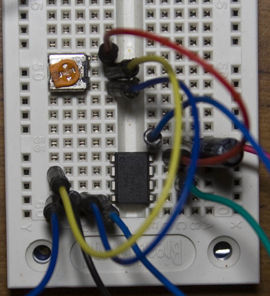
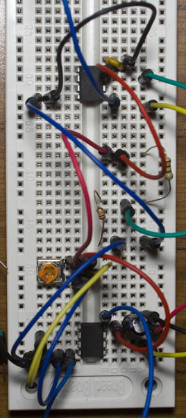
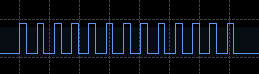
Testing frequency pickup on the breadboard
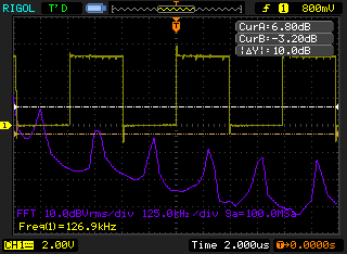
Here’s the 128KHz output from the ATtiny, I found the FFT function and we can see that the highest dB is at 128KHz, the next point is 256KHz which is due to the harmonics and so on.
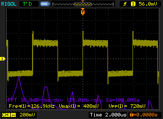
I decided to see how breadboards can pick up this so I placed the output wire on one strip and the probe on the next strip up. From 5V we go down to 200-250mV but still that’s quite a bit of noise.
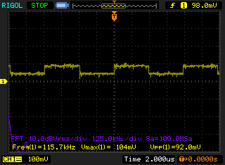
From 14 strips away, you can still pick up a little bit of the noise.
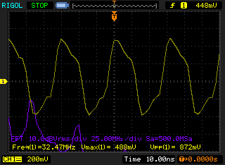
With 32MHz and 1 strip away, we go down from 5V to about 450mV.
ATtiny ADC results
Now let’s test reading from the ADC on another ATtiny. I’m running from 5V and it’s reading a 1M / 10K resistor divider which should give about 49mV.
Here’s how it looks with the VCO PB1 output disabled, a high and low represent a value of 1. We have a ADC reading of 9 which gives 9 x 0.0048828125 = 43.9mV which is close.
Now with VCO PB1 output enabled and the wire is going to the other ATtiny about 3 strips away, we see a ADC reading of 5 and 13 which means we have 24.4mV and 63.4mV which is jumping around quite a bit. For higher voltages: a 100K / 10K resistor divider I get about 4-5 counts out in the ADC readings and with a 10K / 10K divider I notice 1-2 counts out sometimes so it’s something to watch out for!


[…] ATtiny25 Elementary VCO, RC oscillator overclocking furthermore testing frequency pickup – understand else about this enterprise relate […]
Nice project, i try to get this working on other attiny (13 and 2313) and on a arduino but so far no succes. (will get there evetually if posible at all on the 13 series…) also will try with 45 buy don’t have one available yet…
Now i also wonder what the max frequency is, and if there is a way to control the duty cycle
i’m searching for a way to make frequency variable from 2khz up to 200khz or more with a duty cycle from 1% up to 50%
I see how to make an osc OR a pwm in this way, but my goal is a osc AND pwm in one, and that seems to be more difficult then i expected. sure i can go back to 555 but wouldbe nicer if i could pull this out of an attiny. that’s cheaper, more power efficient and less components / assembly errors.
Hi Wilfried,
If it’s just 2KHz to 200KHz or about that range and the MCU wasn’t doing anything else then potentially it could be easier to implement it all in software instead of using the timers to generate the PWM as long as you run fast (like 16MHz+). You could just use 1 timer to count the cycles and then use a 10K pot with 10 turns to control the frequency and another for the duty cycle.
E.g 16MHz with 200KHz as the selected frequency you want, 80 cycles to play around with. So for 25% duty, you would want to toggle high on 0 to 3 and then 4 to 80 go low, then reset the counter.
Should be 0 to 20 high, 21 to 80 low
Hello!
Please, can I have schematic?
On breadboard I can not see how must all be connected and how much uF is capacitor?
I will build VCO for frequencys beetwen 64 til 65 MHz with step of 5 kHz.
Is that possible?
Thank you very much for help
Hi Michael,
I didn’t make a schematic as there wasn’t much to it, just PB1 is the output and PB3 has the 10K pot middle wire to it. The capacitor is a de-coupling cap about 10-100uF.
With this setup to reach 66MHz I was just incrementing the OSCCAL, you won’t see a resolution of 5KHz, it’ll be more like 0.25-0.5MHz.
Thank you very much Alex for answer.
Is there any solution that I maybe can become resolution of 5 KHz?
Or maybe that I can become frequencys 64.05 MHz and 64.35 MHz?
This circuit is best solution for cheap and good VCO with only few parts.
Best regards,
Michael
Hmm, the only VCO related part I have some experience with is the Cypress CY22150 (http://www.insidegadgets.com/2014/02/17/playing-around-with-the-cypress-cy22150-programmable-clock-generator/), it could maybe give you 100KHz or ~10KHz resolution (with some variance) if the VCO calculator that Cypress supplies is correct, the part costs $3 or so and you just need a crystal and MCU to control it. I’m sure there would be something better but it depends on how much you want to spend.
The calculator does let me enter in 1KHz changes but it gives you an actual reading of how much ppm it would be out by, if you are looking for something quick to try, I’d say give it a go and see how it goes.
I would like to use this clock frequency to generate an interrupt for the attiny. What would be the name of the ISR routine? Thank you!
Hi Alex,
You would enable the OCIE1A interrupt and the ISR name is TIMER1_COMPA_vect.
Thank you for your patience Alex, I am a noob with timers and interrupts (I am working with ATtiny85).
Do I accomplish enabling the OCIE1A interrupt with
TIMSK |= 1<<OCIE1A ;
Yep that’s correct.
Just be aware that if you are using my example, it can generate interrupts faster than the MCU can handle which means the MCU could be stuck executing your interrupt code.
Yes, understood. Thank you.
In my case I don’t need to generate more than 2mhz (I m looking at variable sampling frequency for audio app) but I really like the flexibility of you approach.
How hard would it be to turn this into a Game Boy overclocker circuit. Could make it with 5 separate frequencies to make it run at speeds of 0.5x(2MHz) 1x(Default:4.194MHz), 2x(8MHz), 3x(12MHz), 4x(16MHz). Would wire the 4 GPIOs to the GBA buttons to allow changing in game with no need for an external switch. Such as holding two buttons and pressing up or down to change the speed.
Hi,
Yep that would be achievable, it’s more accurate in the low end clocks than high end ones, you’d just have to play with the timer settings to suit (doubt it would be bang on 4.194 but close to it). Otherwise if you want accuracy, try the CY22150 – https://www.insidegadgets.com/2014/02/17/playing-around-with-the-cypress-cy22150-programmable-clock-generator/
Thanks for the response. Within 5% of 4.194MHz would probably not be noticeable to the average person and the higher speeds are just for speeding through slow scenes where accuracy is not important at all.
I looked at the CY22150 but new the Attiny’s could output a clock signal and found your post. I can do it all with just an attiny and run off the GBA’s 3.3v regulator.
Ah yep, within 5% should be fine I believe.