A little while ago I saw one of mikeelectricstuff’s videos about interfacing with the iPod nano’s screen using a CPLD. A CPLD is a complex programmable logic device, it’s similar to an FPGA, has a bit less capacity but has its configuration file stored on chip where as the FPGA has its configuration on a memory chip and generally only uses 1 voltage rail.
So what can we use CPLDs for? We can use CPLDs for high speed devices such as an I/O expansion, interfacing with SDRAM, LCDs, combining lots of logic of various chips into one device and so on. An advantage over MCUs is that CPLDs can have multiple logic operations occurring in parallel however it should be noted that with some CPLDs you can only re-program them up to 100 times.
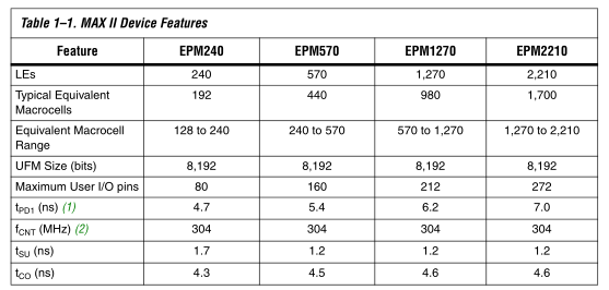
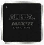
The CPLD we’ll be looking at is the Altera MAXII EPM240 which contains 192 macrocells (the more you have the more logic you can configure), 80 IO pins and can operate at 304 MHz at the highest speed grade. There are also lower macrocell/pin/cost versions of CPLDs too, the Max3000A EPM3064ALC44-10 (100MHz) has 64 macrocells with 34 user pins, is about $3 AUD. It’s in a PLCC package which allows you to use sockets if you don’t want to solder the TQFP package.
As a quick example, lets say you had a design which had 3 shift registers controlling an LED matrix. Normally if you were just using an MCU with the 3 shift registers, you would have to shift out to all the shift registers every couple of milliseconds to keep the refresh rate up. The CPLD could replace the 3 shift registers, potentially saving you board space and you could have your MCU send the data to the CPLD only when the frame had changed. The CPLD would constantly be refreshing the display by itself which leaves the MCU able to do other things.
Before we get started, I’ll link to some resources:
- Altera CPLD/Quartus II Software Online Training – Good to learn about CPLDs in general, the expressions in Verilog/VHDL, Quartus II software interaction, you could spend easily spend several hours on these.
- EEVBlog – What is an FPGA – with advantages and disadvantages
- Verilog Lectures by Kirk Weedman – Highly recommend these lectures, learn about using Verilog and ModelSim. If you go through lectures 1 to 4, that should cover most of the basics.
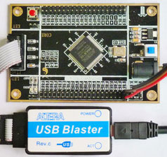
I bought a CPLD Dev board with the USB Blaster which uses JTAG to program the CPLD, it cost about $35 AUD.
Let’s get started, first download and install the Altera Quartus II (make sure you also get ModelSim) and create your first project using this guide: FPGA4Fun Altera Quartus II quick-start guide. We’ll be using Verilog over VHDL as Verilog is more similar to C code than what VHDL is.
.
Some example code
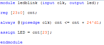
Lets break down the code. At the start of each module, you specify the pins that are used such as the clock pin and led pin. You can have interconnecting “wires” with-in the CPLD in here too. We specify which directions the pins are, clock is an input which is connected to our 20MHz oscillator that’s on the CPLD board I’m using, led is an output which we connect to our LED.
Next we have our counter register (cnt) which is 24 bits wide – think it of like a variable.
We need a way to make the CPLD perform something which can be done with the always command, we specify if it’s a rising edge (posedge), negative edge (negedge) or we can specify if any pins change by just listing the pin itself (e.g always @ (clk) however not all CPLDs support this). By triggering on the positive edge of the clock signal, we execute the counter code which increments itself. 24’d1 means that the decimal value of 1 is 24 bits wide, since all other bits of this value are 0, you could write it simple as 1’d1 since we already declared cnt as 24 bits wide.
At any time where the 24th bit in the variable cnt[23] is 0 or 1, this value to the LED which is an output. Since cnt is 24 bits wide it will take about 0.83 seconds for the LED to blink on and off (2^24 / 20MHz). Then we write endmodule to indicate the end of our module at the end.
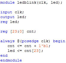
We can re-write this led blink module a different way. Now instead of specifying the pin directions straight in the module, we specify it later on. We no longer use the assign statement on the LED, so in order to write a 1 or 0 to the LED we need somewhere to store it to, so we have a register led that’s as many bits wide as the output led – 1 bit.
Because we are executing more that 1 line in the always statement, we use begin and end to indicate the block of code to execute. We do the same as before, except this time the value we keep adding on to itself is 1 bit wide and is a binary 1. Then we assign the led to the 24 bit value of cnt like before.
.
Assigning pins, RTL viewer and Programming the CPLD
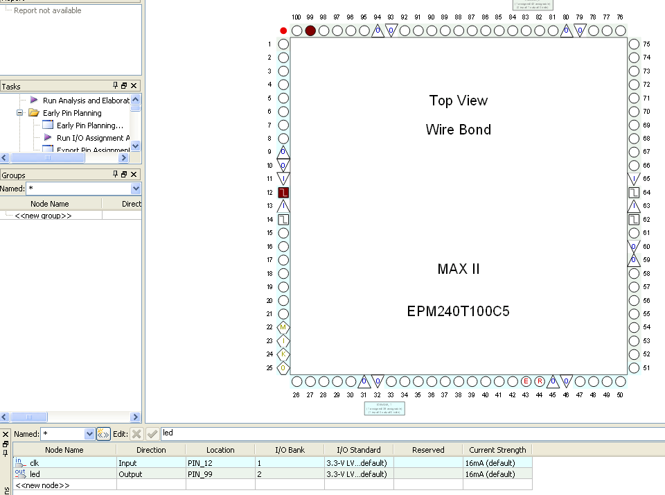
You can use the pin planner or assignment editor to choose where the clk and led pins go; you drag the pin to the location on the CPLD.
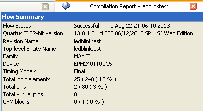
After you run “Start Compilation”, you can see in the compilation report window how many logic elements you’ve used. We’re using 25 out of 240 elements, mostly because we use a 24 bit register.
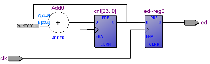
We can see how the our design looks in the RTL Viewer by going to Tools > Netlist Viewer > RTL Viewer; our input clock signal going into 2 registers, an adder and our output led pin.
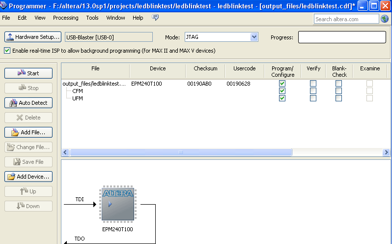
Now we can click on Programmer,tick on “Program/Configure” then press Start.
https://www.youtube.com/watch?v=XKbeqAi7FfA
Powercycle your CPLD so that it can reload its configuration and we have our blinking LED.
.
Using ModelSim
Simulation is very important when working with CPLDs or FPGAs, it lets you check how all your logic will act and you are able to run all kinds of test cases. We’ll be testing how our LED pin acts when the clock signal is applied to it.
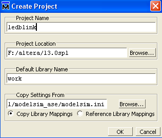
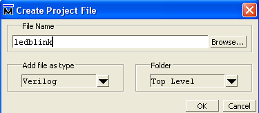
Let’s get started by creating a new project and then a new file.
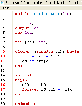
Copy our existing code into the text editor, we’ve make some adjustments so the code will simulate. We removed the clock as an input and have set it to be a register. We added an initial block which will execute first, it sets the clock to 0 and then every 5 time units the clock will be inverted. I changed the counter to be 3 bits otherwise having 24 bits would take too long to simulate.
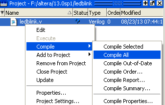
Now compile the file.
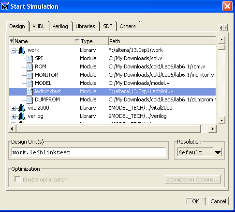
Go to Simulate > Start Simulation, select work and choose the ledblinktest.
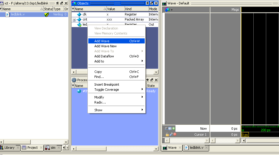
Switch over to the Wave view near the bottom right, select all the objects we wish to monitor in the objects list, right click and choose Add Wave.
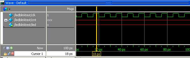
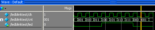
Now press F9 and press F for “Zoom full” to see the wave form to fit the window. We see the clock switching high and low every 5 ps however the counter and led are marked as x. This is because we didn’t specify the initial values of those two registers, i.e reg led = 1’b0 and reg [2:0] cnt = 1’b0. You could also add these values in the initial block where the clock is if you like.
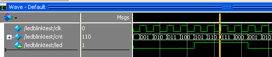
All values are in binary, you can change that by right clicking the variable and selecting Radiax > Unsigned if need be. Press the restart button and then F9 to refresh the wave. Now we can see the counter changing at every positive edge of the clock and the led turns on when the counter’s 3rd bit is 1 – sort of. You’ll notice that this doesn’t happen immediately but on the next clock cycle, this is because we use the non-blocking statement (<=) instead of the blocking statement (=) when incrementing the counter and switching the LED on or off.
Think of the non-blocking statements all happening at the same time when time is frozen. A snapshot is taken of all objects, then all the non-blocking statements are run on the objects from the snapshot independently from one another. When the counter equals 011 and there is a positive edge, the counter increases to 100 as normal but then led takes the snapshot version of counter and since it’s still 011, led is still set as low.
If you wanted to over come this, you can use blocking statements such as the below which executes sequentially which does put the led high when the 3rd bit is 1.
always @(posedge clk) begin
  cnt = cnt + 1'b1;
  led = cnt[2];
end
Download the cpld_example.
So that covers most of the basics of CPLDs and using the Quartus software. The reasons I’m looking at CPLD is to see what I can build with them, initially I thinking I could make an logic analyser with a low priced CPLD (100 MHz) and write the data to SRAM which could be read out by a MCU later on.


What’s the name of the dev board you’re using? Or the link to it’s product page?
Also, the resources you linked look very helpful. I’ll have to go through them later on.
Thanks!
Hi Dillon,
I bought the dev board from Ebay, it’s the Altera MAX II EPM240 Core Board FPGA CPLD Development Kit – http://www.ebay.com/itm/Altera-MAX-II-EPM240-Core-Board-FPGA-CPLD-Development-Kits-JTAG-USB-Blaster-/330813186044
I can’t figure out how to start a new Quartus II project with a CPLD as the target device. Only FPGA families are listed in the New Project Wizard options. Any help?
Hi Anthony,
You’ll need to download the devices from this link: http://dl.altera.com/?edition=web
You are after the “MAX II, MAX V device support” download.
Hi Alex, thanks for great guide – it just works 🙂
(I’ve used it with this board – the same chip.)
http://www.ebay.com/itm/ALTERA-MAX-II-EPM240-CPLD-EPM240T100C5N-Development-Board-/161755388208