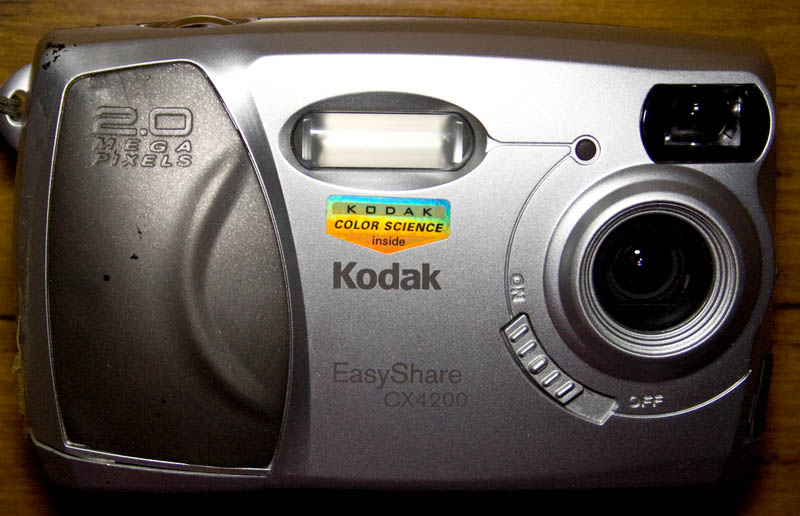
It’s time for a teardown, this time we have a Kodak EasyShare CX4200 2MP Digital Camera which was manufactured in 2002 so it’s now 11 years old!
A few screws later and we’re in.
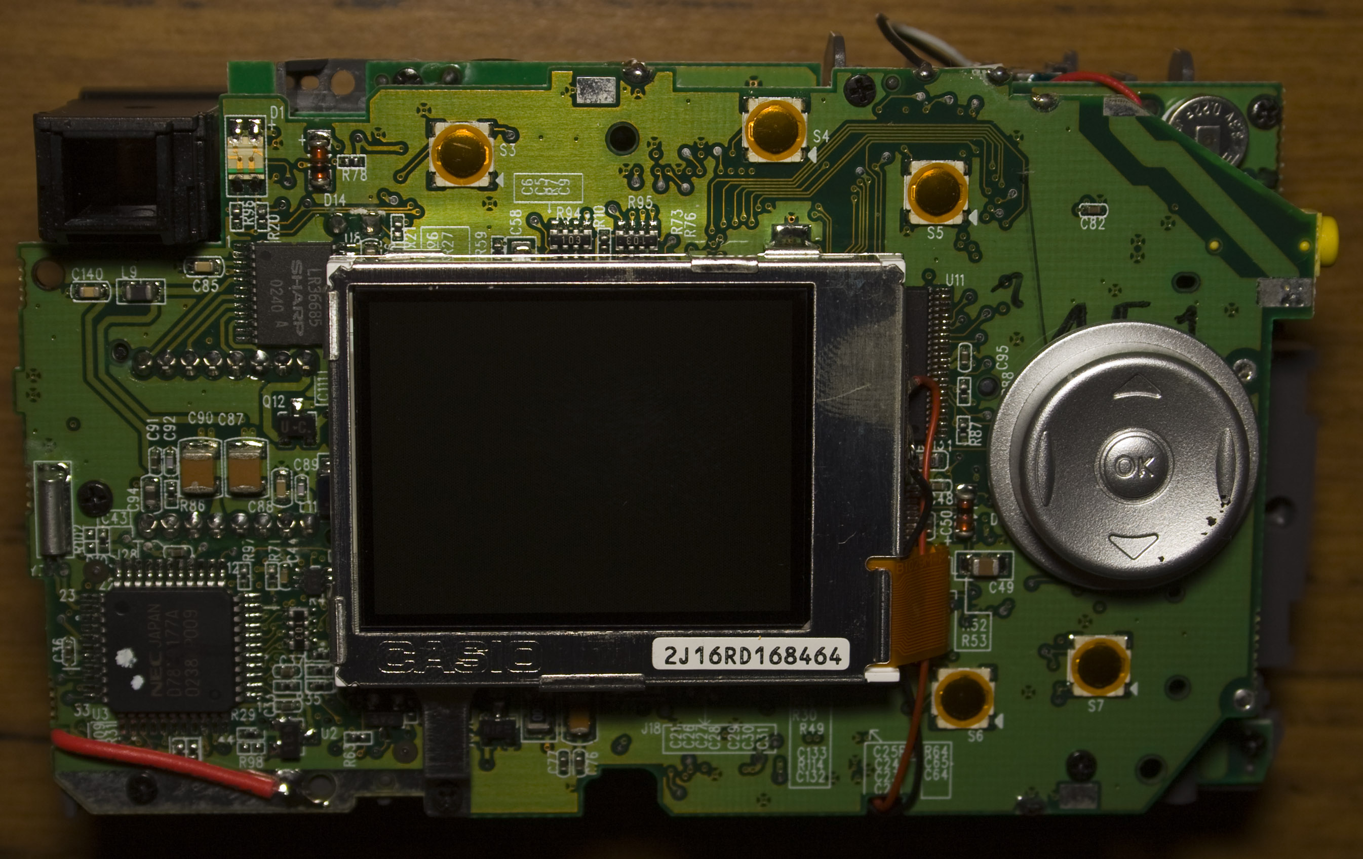
We’ve got the top side which has the AA battery, flash and camera and bottom side which has a Casio LCD. It’s a two board construction with a small interface board just below the CCD.
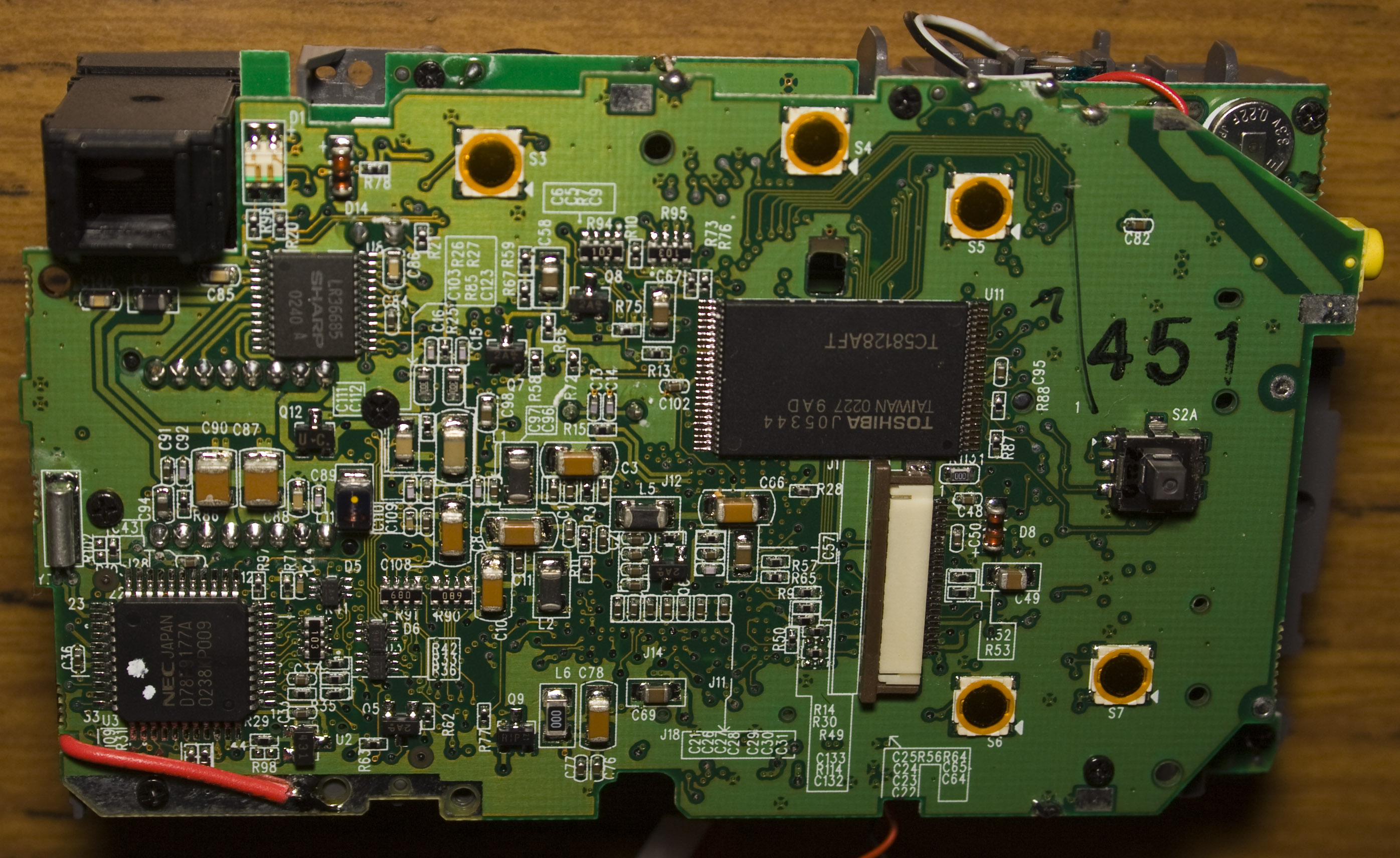
Main board – top side
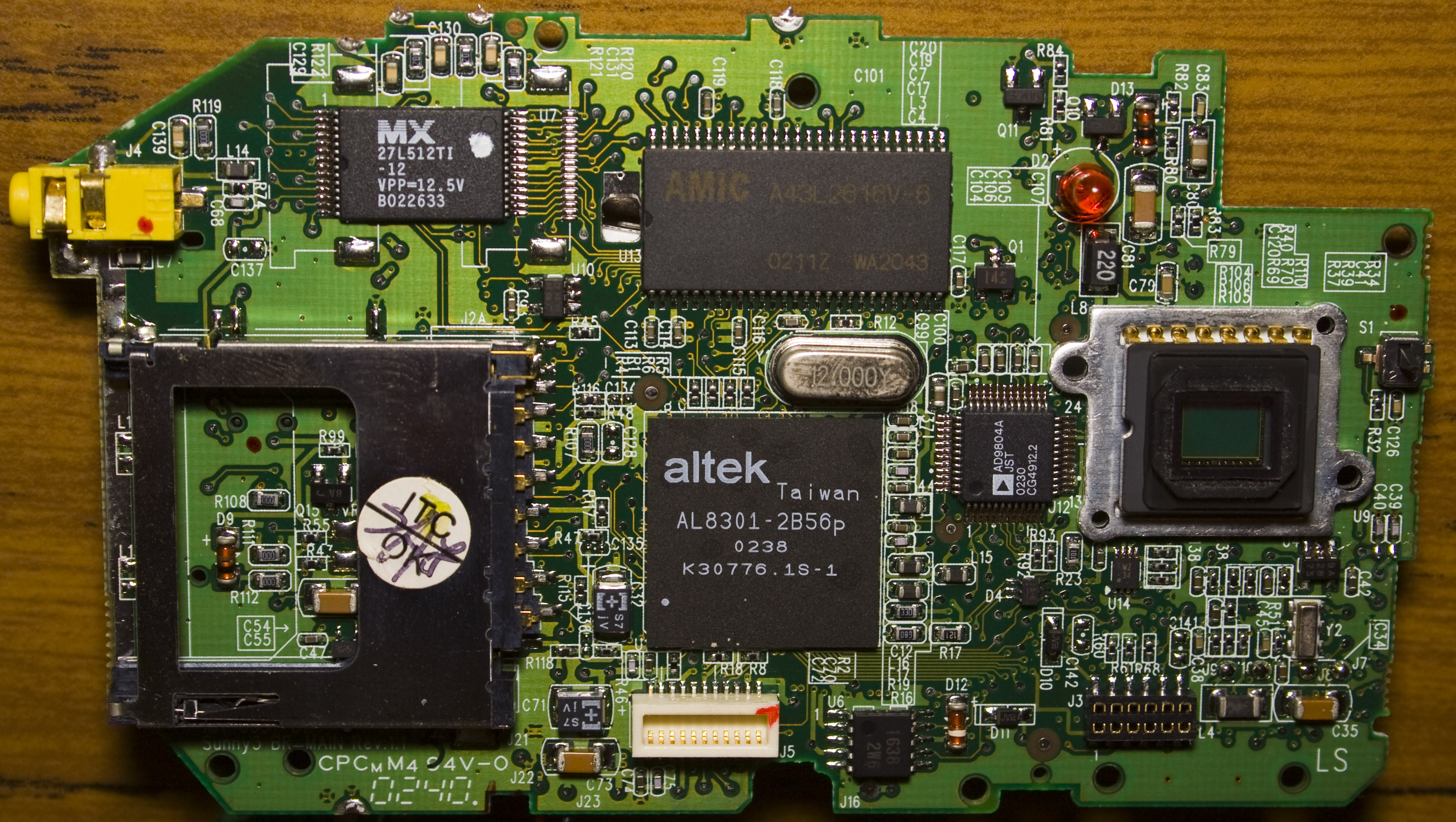
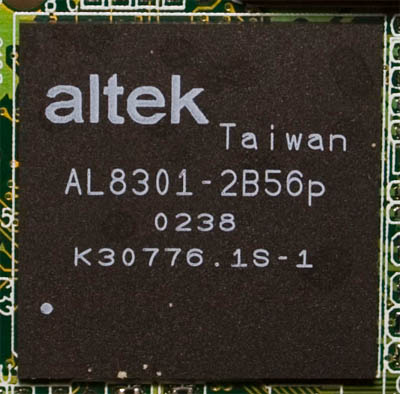
Altek main chip
Couldn’t really find anything on this chip, the Altek site is fairly basic.
AL8301-2B56
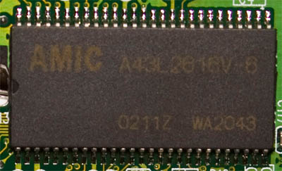
Amic 64Mbit SDRAM
PDF
A43L2616V-6
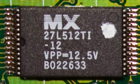
MX 512Kbit EPROM
One time programmable EPROM, PDF
27L512TI-12
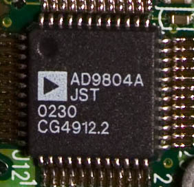
Analog Devices 10bit CCD Signal Processor
Can run up to 18 MSPS, PDF
AD9804A
.
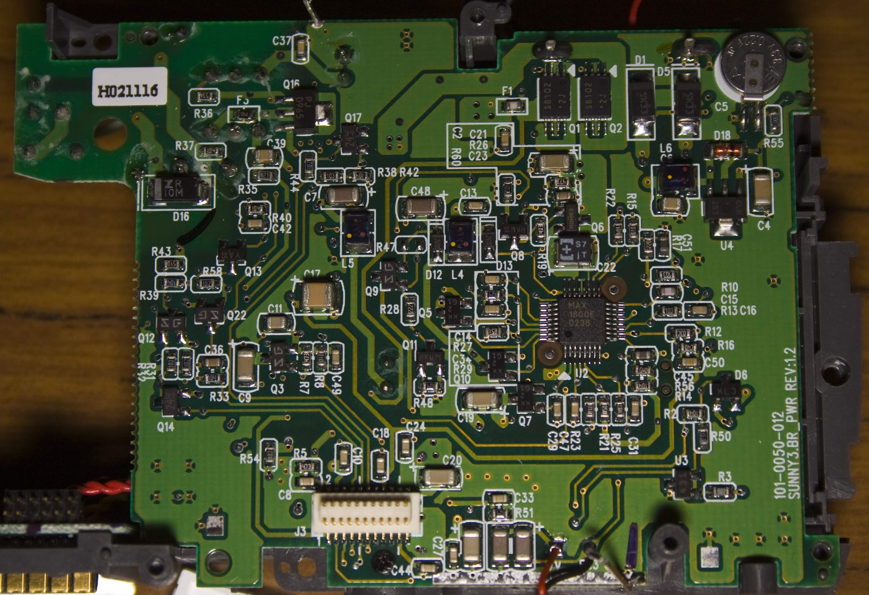
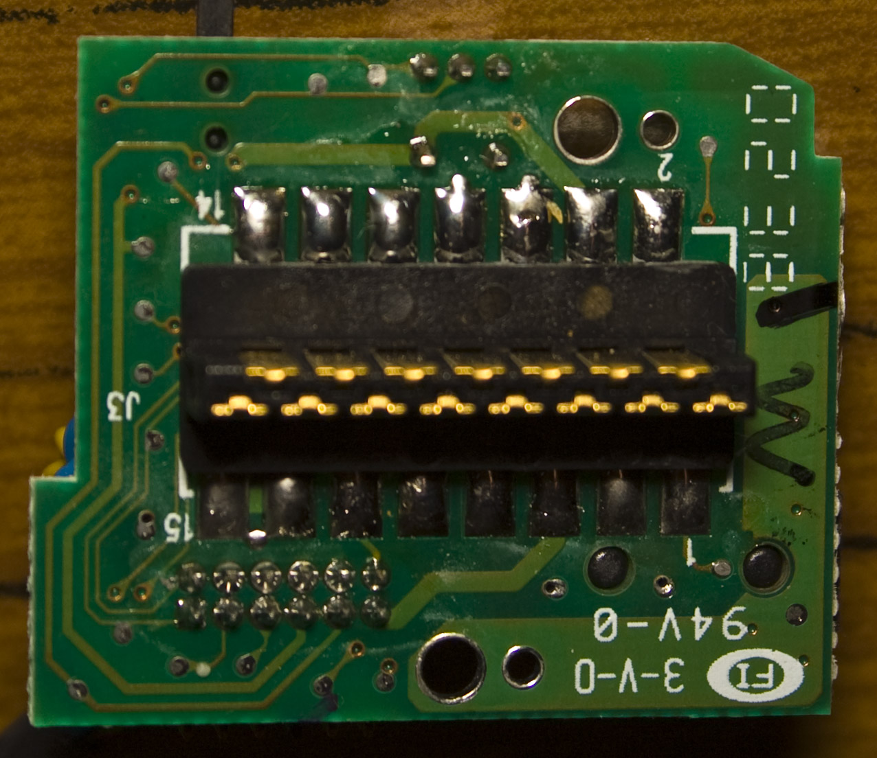
Main board – bottom side
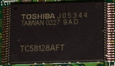
Toshiba 128Mbit NAND Flash
A bit of flash memory, some of which would be used for the internal storage of pictures , PDF
TC5812AFT
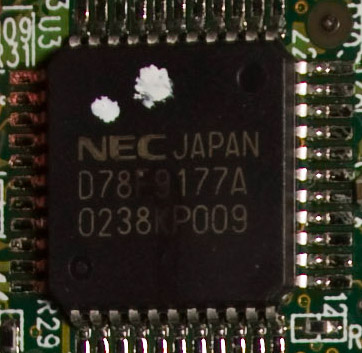
NEC 8-bit Microcontroller
Wtih 24 Kbytes flash and 512 bytes RAM, up to 5MHz, PDF
PD78F9177
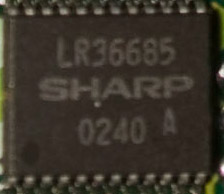
Sharp Vertical Driver IC for CCD Area Sensors
Basically a voltage converter with a few circuits for the CCD: -9 to 0V, -9 to 15V and -9 to 17V, PDF
LR36685
.
Power board – bottom side
Not much here, there’s a Max 1000E chip in the middle which I wasn’t able to find anything on but there is a 3V battery on the top right.
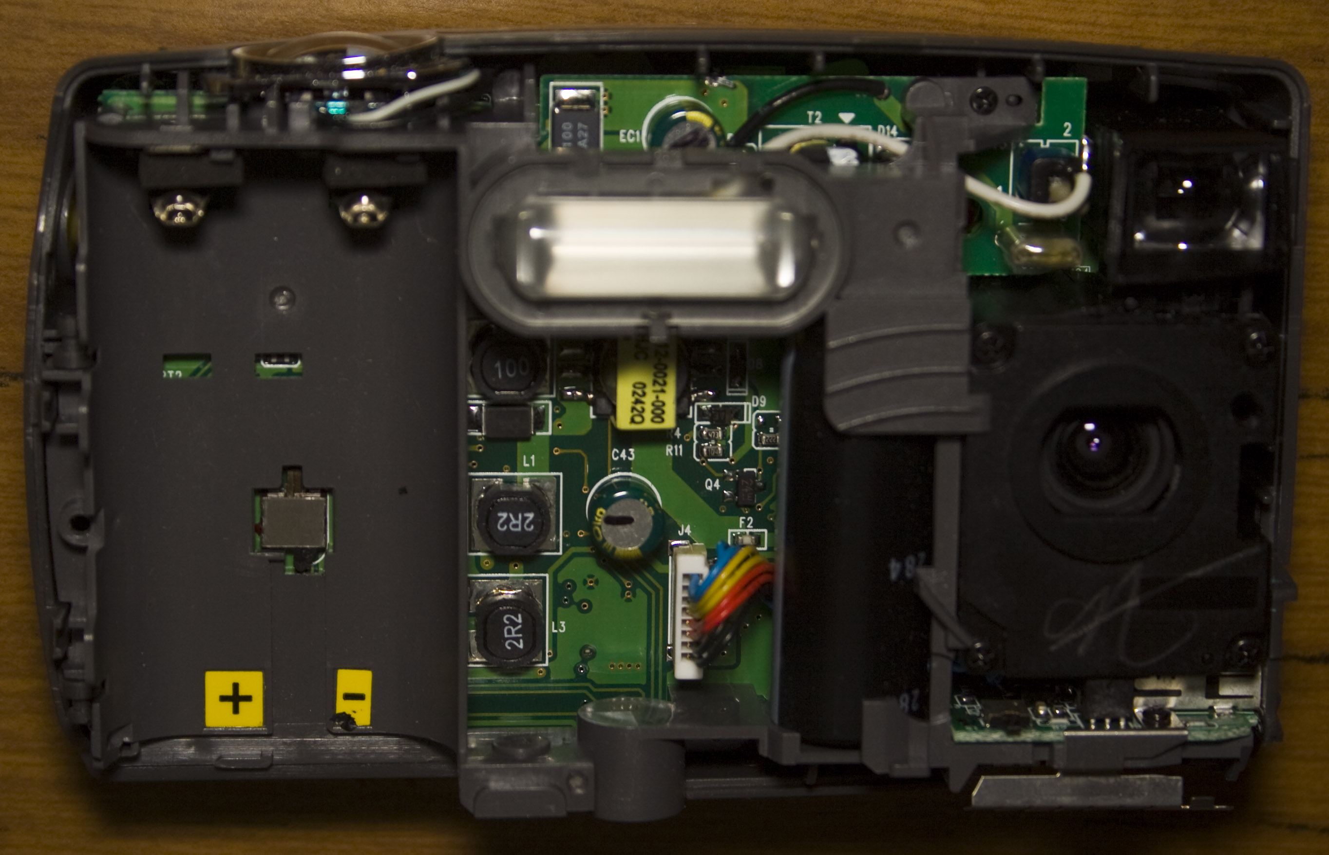
Power board – top side
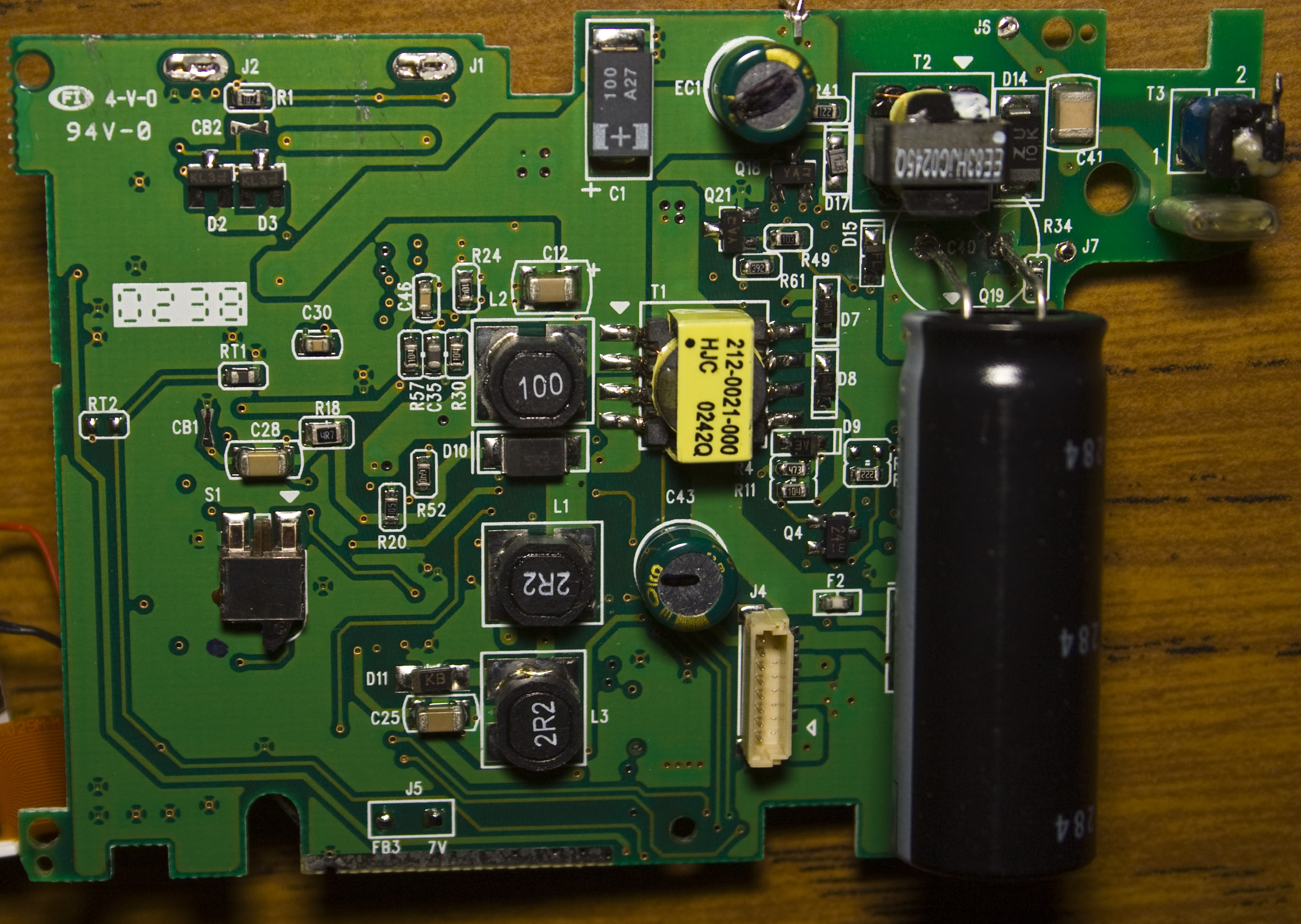
We’ve got the date code of 2002/38th week and we have 3 transformers for the flash, each stepping up the voltage for the flash. The capacitor is rated for 330V 160uF and after leaving the camera off for about 12 hours, the capacitor was still charged, so there’s no bleeder resistor. When I shorted it out I didn’t expect much but there was enough of a spark which surprised me and left a small mark on the small screwdriver I used.
Connector board
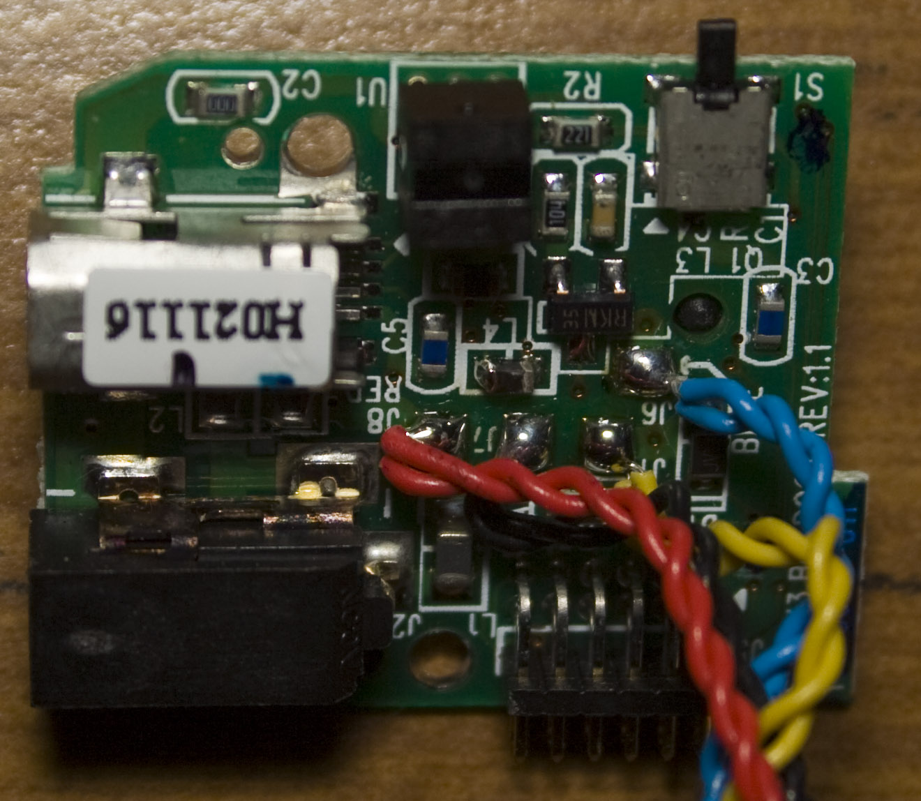
This board has a connector used for docking, it also contains the power on switch. Even though there are two wires of each colour, they all connect to the same point.
Lens Assembly
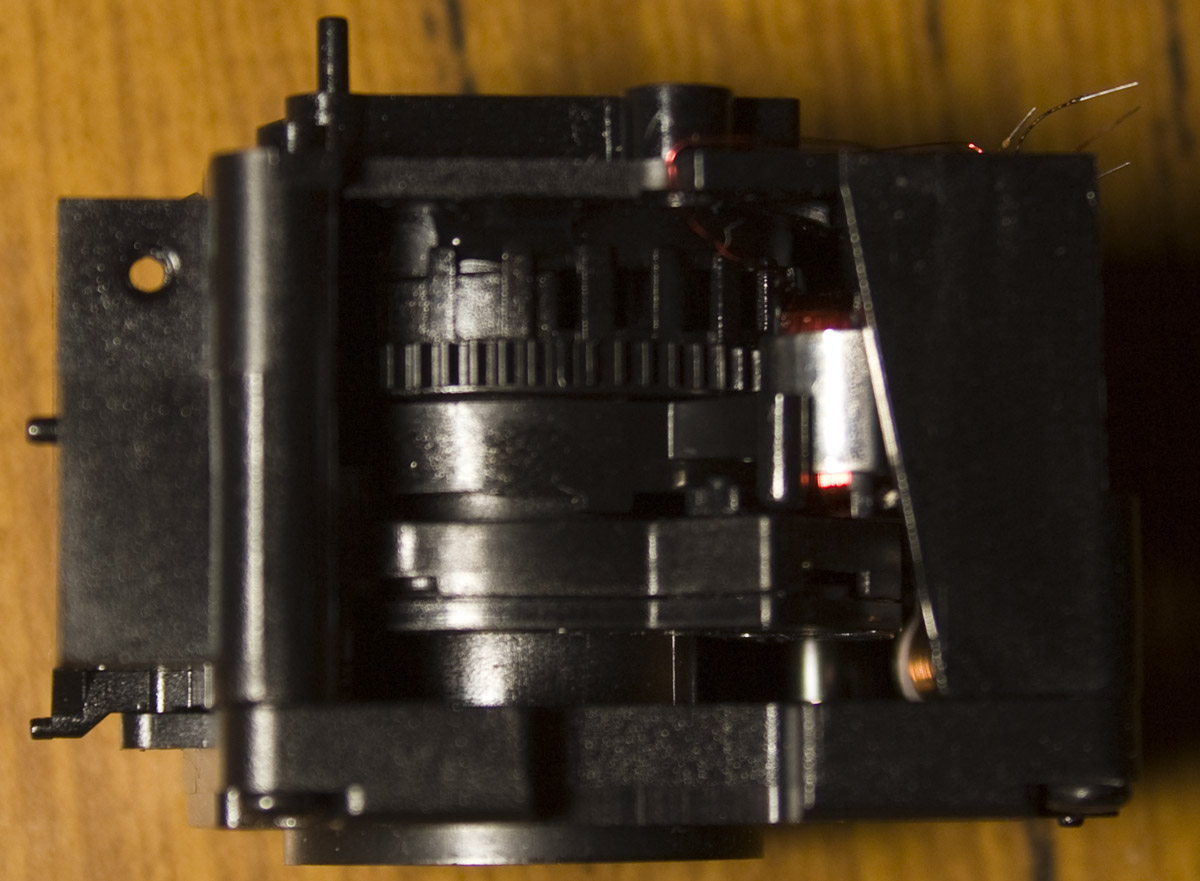
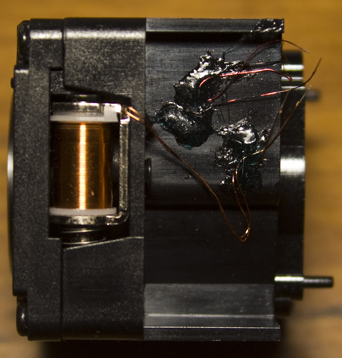
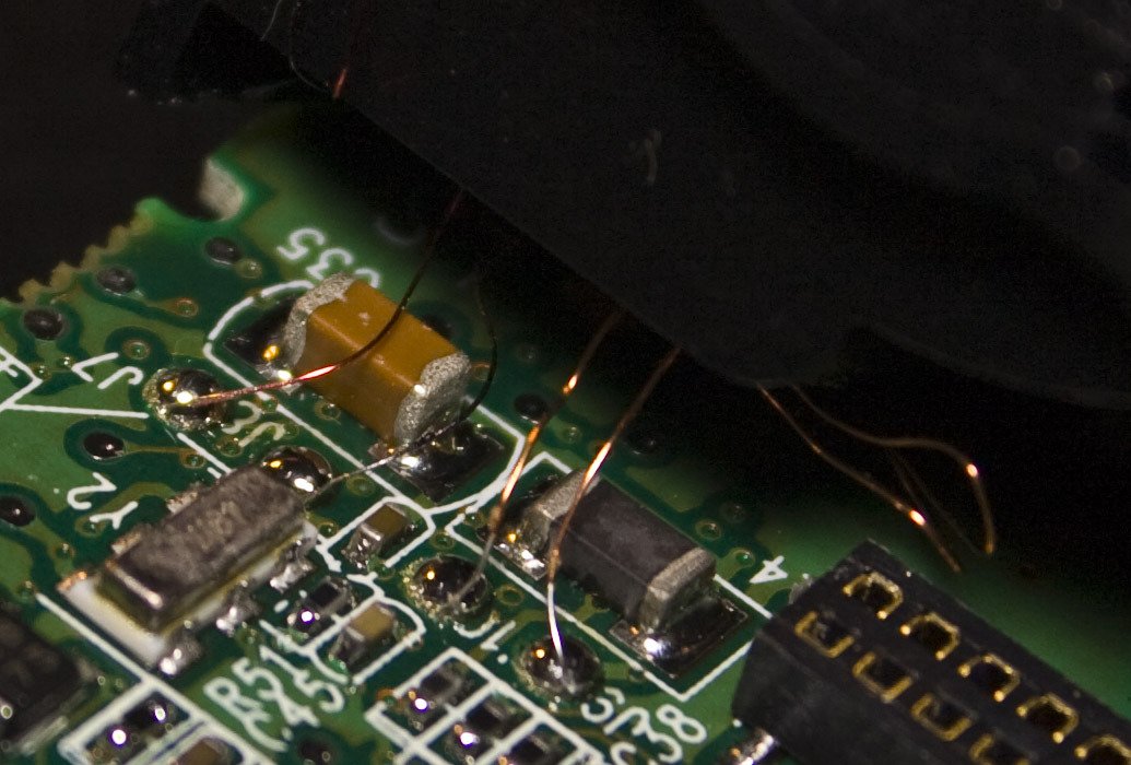
The lens assembly contains what looks like two motors presumably for adjusting the focus. They were connected to the main board by enamel wire.


