I have had a RC car for about 10+ years (15 years old according to the PCB date code) which I think cost $50 at the time and I thought it would be fun to replace the electronic control boards with an AVR and nRF. It used to run on 8AA batteries and the transmitter on a 9V battery. We’ll be having a look at how things were before and how things look now.
(sneak peak of the end result)
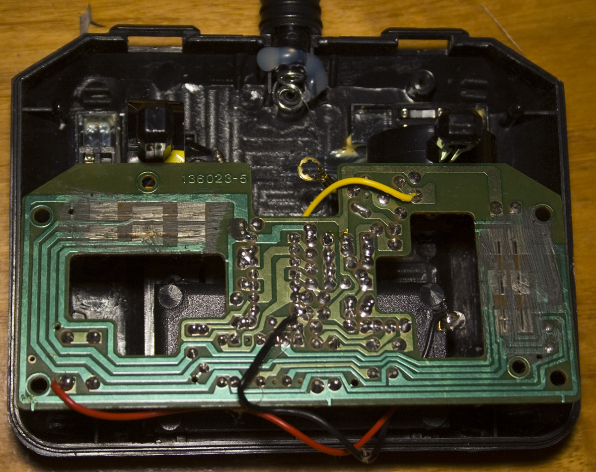
Before – Receiver
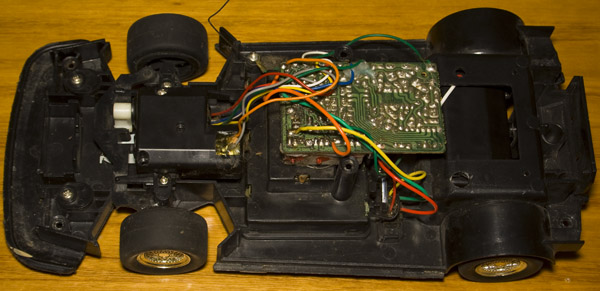
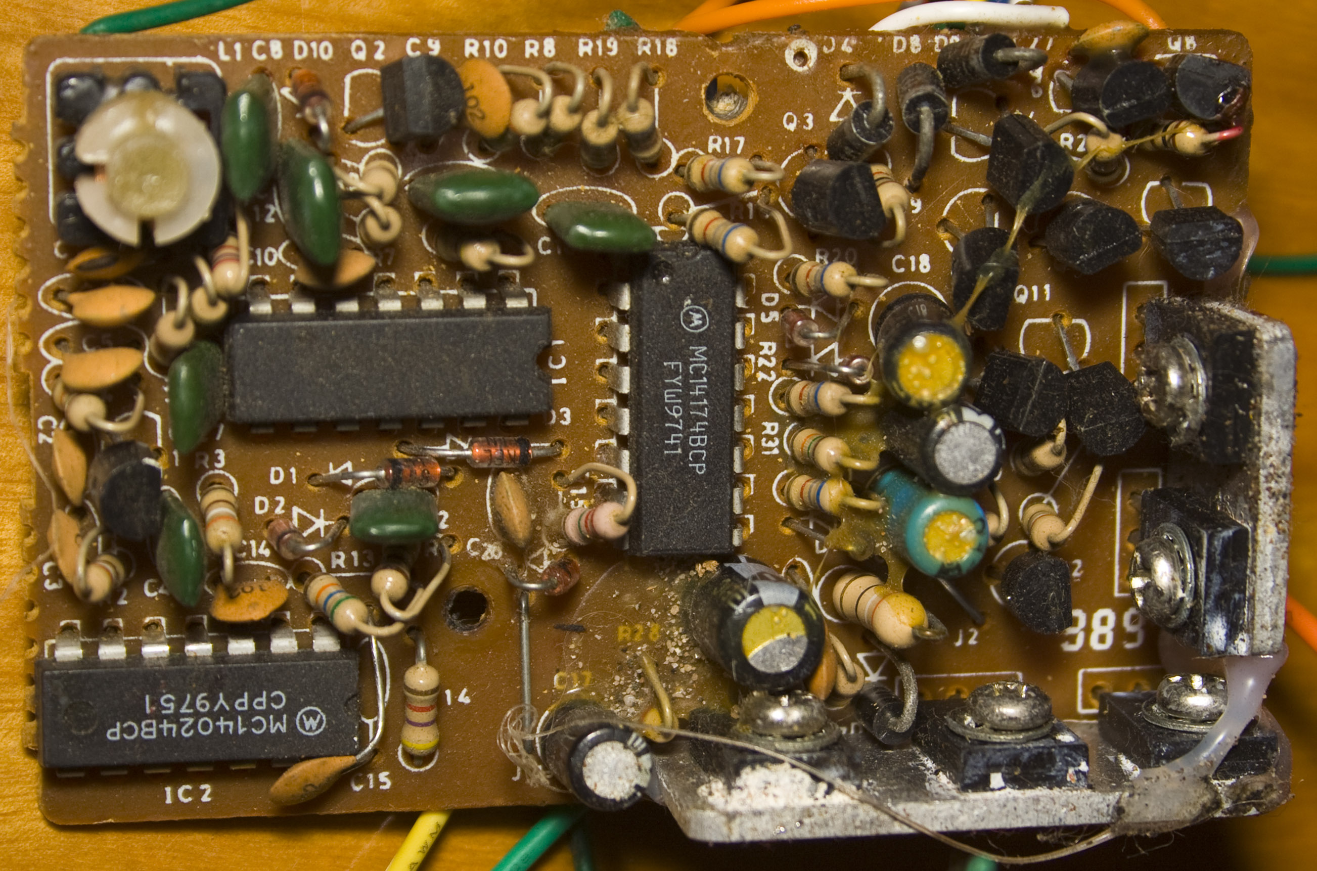
Here’s how the receiver looked before, lots of analog parts with a few IC parts like the MC14174 flip-flop, MC14024 ripple counter and power transistors on 2 heatsinks.
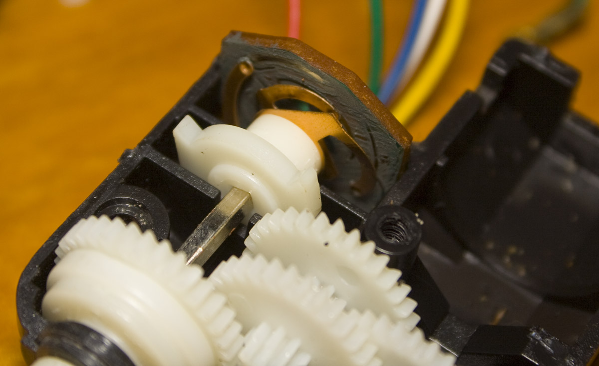
The left/right control is just a motor with what looks to be some form of feedback (with a few wires coming out of it) so it can detect how far to turn the motor.
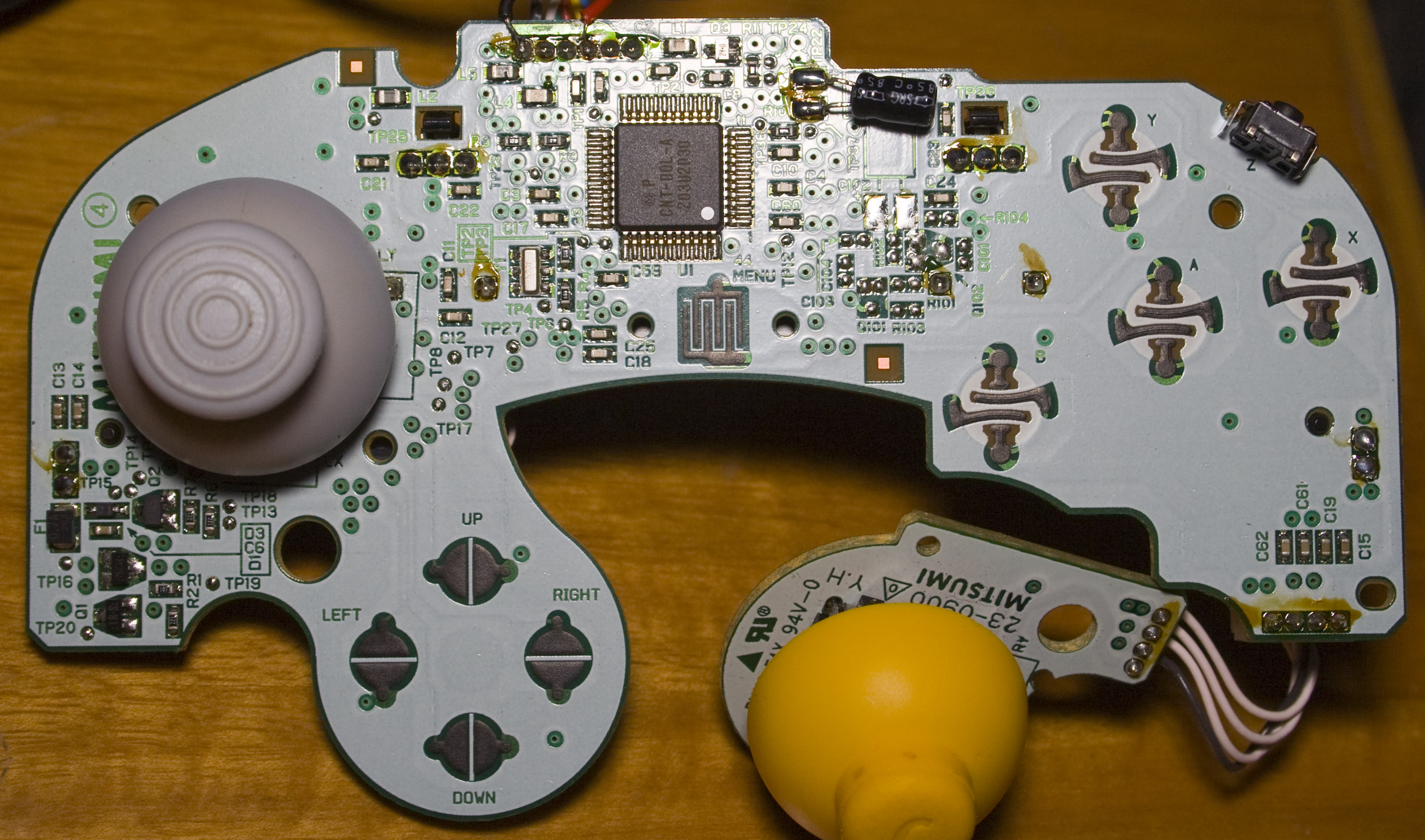
Before – Transmitter
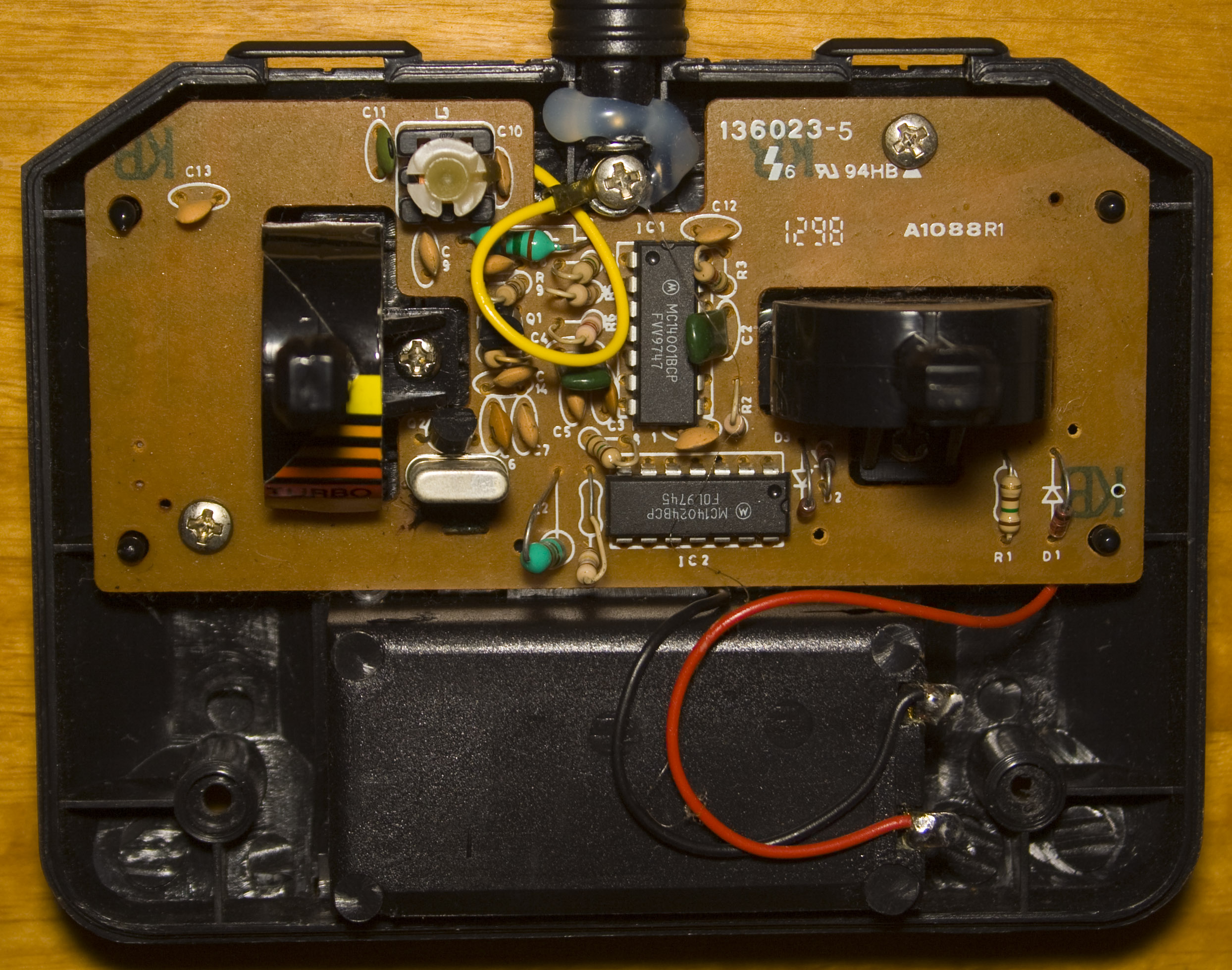
The controls aren’t pots, instead they just move a piece of metal on the PCB between contact points. We’ve got more analog components and two ICs, the MC14024 and MC14001 CMOS gate. PCB date code is 12th week of 1998.
.
After – Receiver
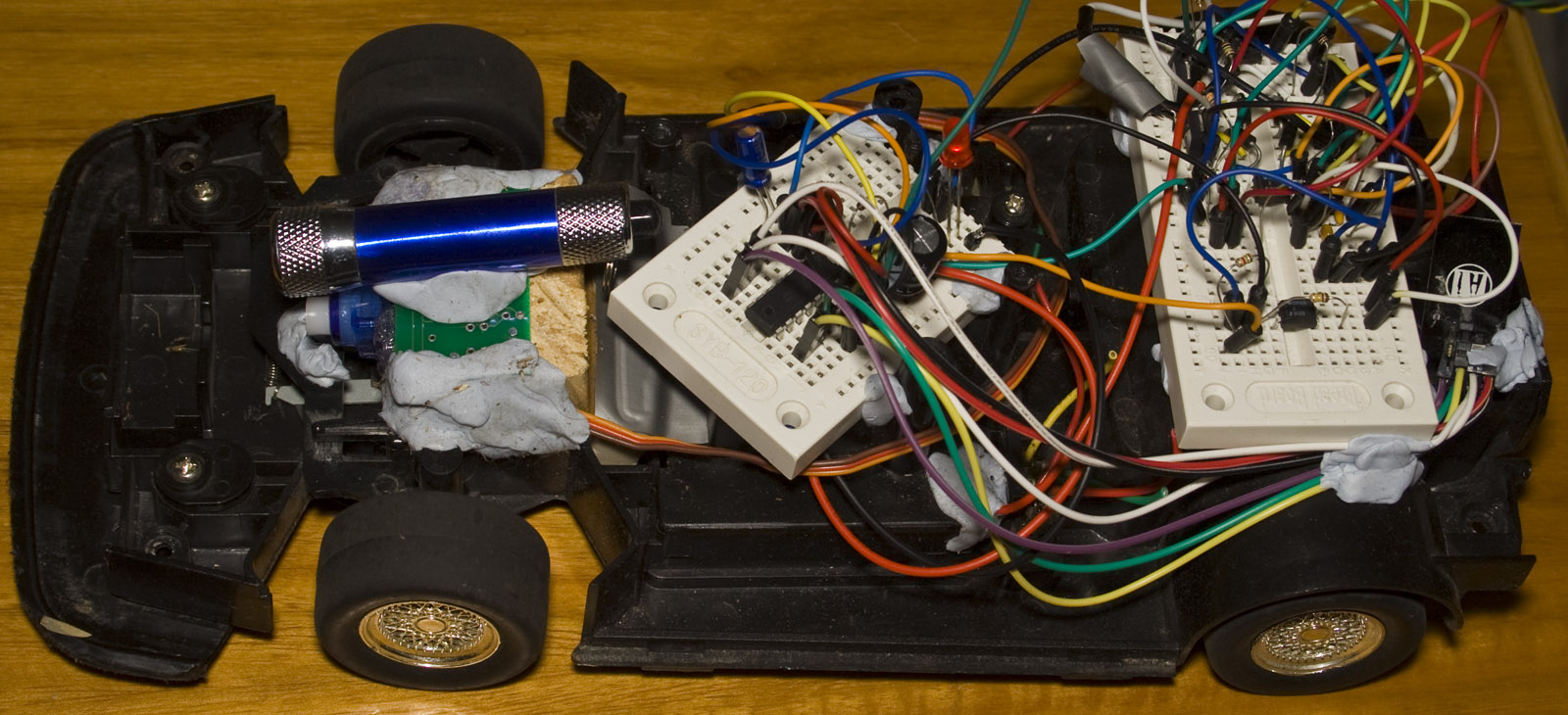
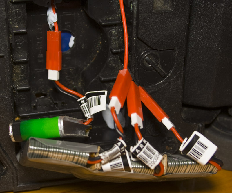
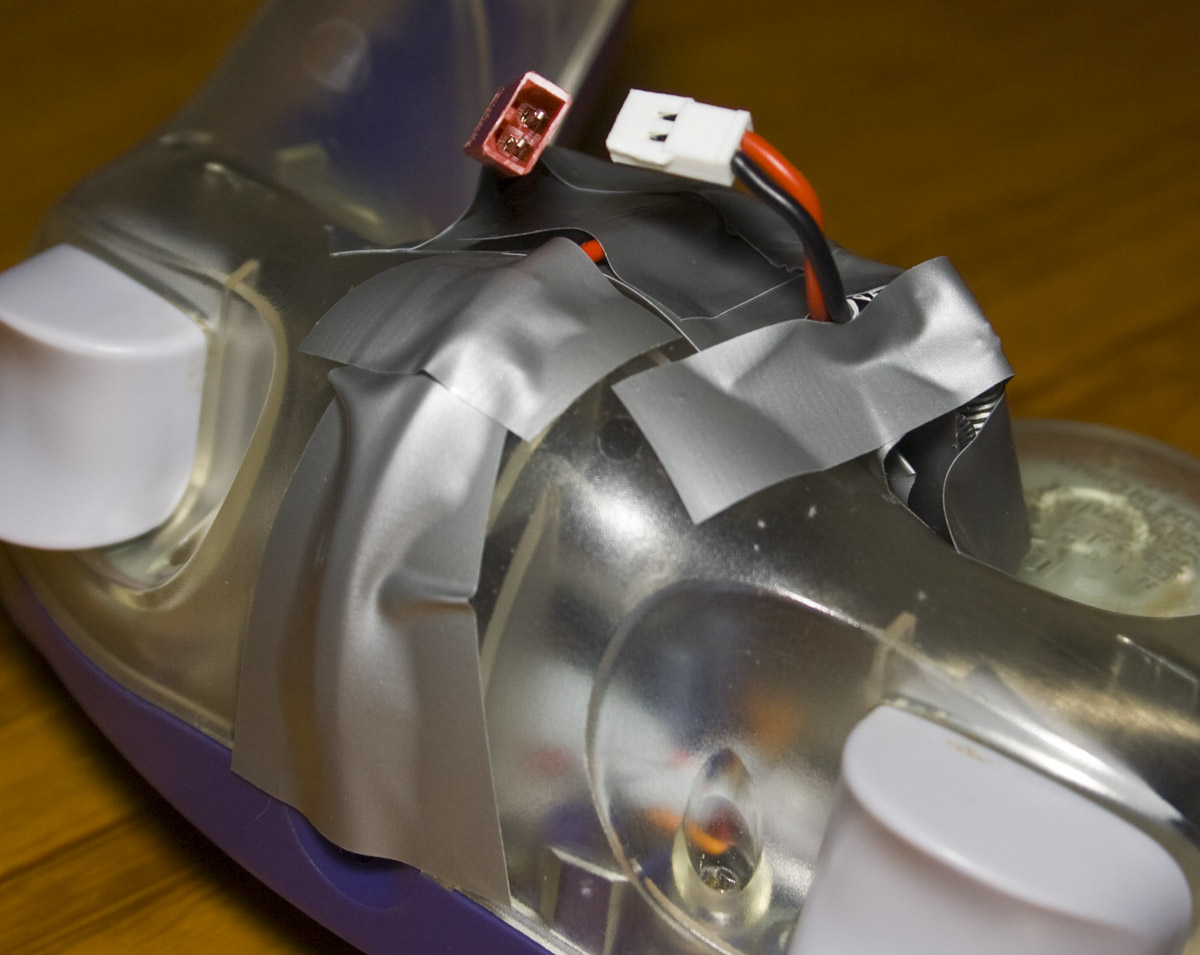
I purchased a few Turnigy single cell 750mAh Lipos from HobbyKing (was going to use them for another project) and I was able to fit in 4 Lipo batteries in the battery compartment; have 3 connected in series for the motor with the 3 Lipos in series to give ~11.7V, I tested out the motor which at no load took 250mA and at stall took 4A.
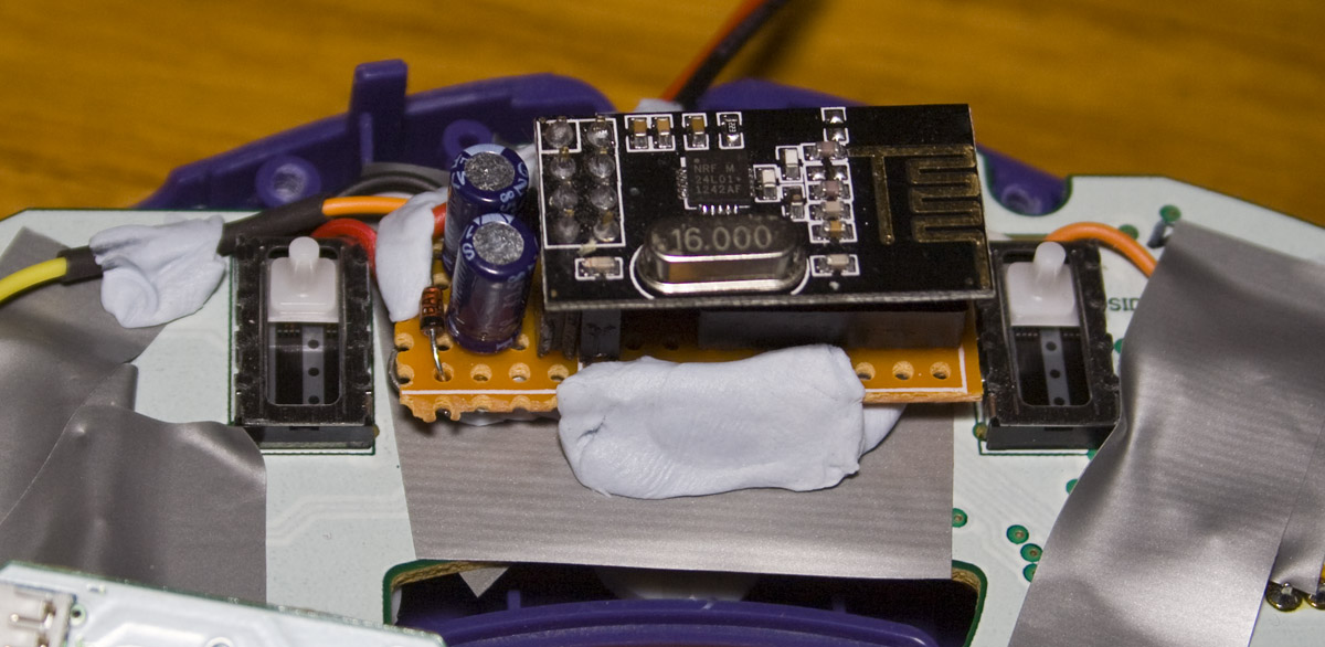
I’ll be replacing the left/right control with a servo which runs on a single Lipo battery, it has a 200-300mA draw. As you can see it’s all hacked together, firstly the servo is screwed into a small wooden block which just fits in, I mounted a PCB on top of the servo with a few nails and then blu-tacked it into place – I should take out the blu-tack and use super glue instead.
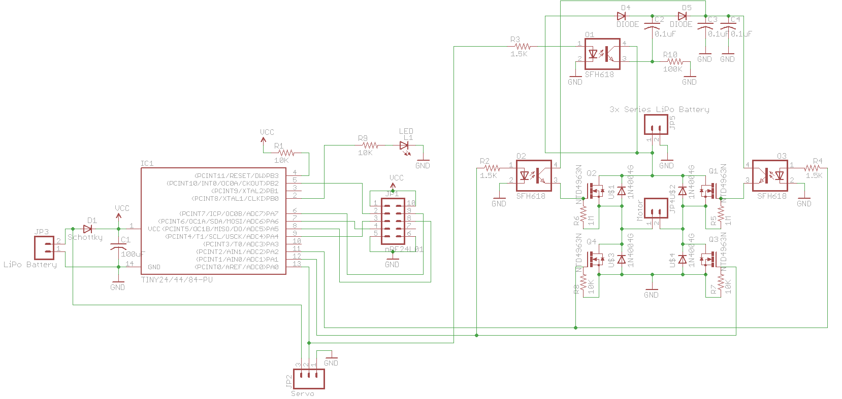
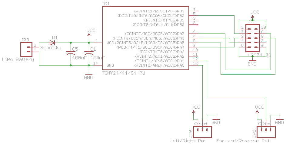
Here we’ve got the single Lipo battery going to the servo and then a schottky diode to power the AVR and nRF. The servo runs at 50Hz with a duty cycle between 0.5ms to 1.5ms using timer1. I have a H bridge using 4 N mosfets instead of going with 2 N and 2 mostly because of cost/size, I’m using the NTD4963N mosfets which can do 8A as a minimum. Since we we have high side N mosfets, the problem is that you can’t really have them fully switched on because of the load taking the voltage drop.
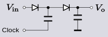
What we can do is hook up a dickson voltage doubler circuit which can double our 11.7V to about 20-22V after the diode drop losses, another resource on how this works is from Dave at the EEVBlog. Since we already have a 50Hz signal for the servo, I decided to connect that signal to the capacitor which we need to pulse and it works well. For the high side mosfets you can see I’ve used a 1M resistor, this is because the 100K resistors which I normal use were drawing too much current which made the doubled voltage decrease. I’ve used another two opto-isolators to select between the two mosfets.
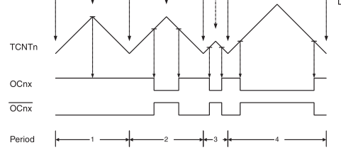
Initially it may seem that we are providing a 22V Vgs to these mosfets, but in reality it’s only about 11V due to the low side mosfet. Using timer0 we can switch the high side and low side mosfets on and off together. Initially I choose 2KHz but found that it was too fast because the temperatures of the mosfets rose very quickly, I settled with going 60Hz.
RX Code
wdt_disable_reset(); // Disable the watchdog reset

// Change 1 MHz to 8 MHz by changing clock prescaler to 1
CLKPR = (1<<CLKPCE); // Prescaler enable
CLKPR = 0; // Clock division factor 1 (0000)

// Blink LED to show we are turning on
...

// Enable watchdog reset for 4 seconds
wdt_enable(WDTO_4S);

spi_init(); // Initialise SPI

// Set up servo
DDRA |= (1<<PA0); // Servo connected to PA0
TCNT1 = 0;
TCCR1B = (1<<WGM13) | (1<<CS11); // PWM, Phase & Freq. Correct, 8 prescaler
ICR1 = 10000; // Sets frequency to 50Hz / 20ms
OCR1A = SERVO_CENTER; // Sets 1ms (servo centre)
sbi(TIMSK1, OCIE1A); // Output Compare A Match Interrupt Enable

// Set up motor
DDRA |= (1<<PA1); // Motor forward control (low N mosfet)
DDRA |= (1<<PA2); // Motor reverse control (low N mosfet)

sei(); // Turn on interrupts
Now we can have a look at the code. When testing the car out I found that sometimes I would lose control of it and I suspect this was due to the wires shaking around a bit as I didn’t have any problems when it was stationary, so I’m using a watchdog timeout to generate a reset after 4 seconds.
We use the 16bit timer1 to generate the 50Hz signal using phase and frequency correct PWM for the servo, divide the 8MHz by 8 to give 1MHz and because we are switching it on and off, we set it up as 10ms which will give a 20ms/50Hz and the center position of the servo was 1ms duty cycle. We can’t use the OCnx hardware port to switch the output high and low because we are using it for SPI, so we’ll use the interrupt instead to XOR another port.
if (mirf_status() & (1<<RX_DR)) { // Check if a packet arrived
// Reset the watchdog
wdt_reset();

// Read the packet
...

// Left/Right control
int leftrightReading = data_in[LEFT_RIGHT_CTRL] * 2;
if (leftrightReading > 300) { // Right
  leftrightReading += 18; // Fine tuning
}
else if (leftrightReading < 200) { // Left
  leftrightReading -= 30; // Fine tuning
}
OCR1A = 750 - leftrightReading;

// Motor control
int forwardreverseReading = data_in[FORWARD_REVERSE_CTRL];
if (forwardreverseReading > 150) { // Forward
  // Fine tune the motor control
  uint8_t calcOcr = 0;
  for (int x = 0; x < (forwardreverseReading-150); x++) {
    calcOcr += 2;
  }
  if (calcOcr > 170) {
    calcOcr = 250;
  }

  OCR0A = calcOcr;
  motorDirection = MOTOR_FORWARD;

  if (prepareMotorForStart == 1) { // Turn on timer once
    TCNT0 = 0;
    TCCR0A = (1<<WGM00); // PWM, Phase Correct
    TCCR0B = (1<<CS02);
    sbi(TIMSK0, OCIE0A); // Output Compare A Match Interrupt Enable
    prepareMotorForStart = 0;
  }
}
else if (forwardreverseReading < 100) { // Reverse
  ...
}
else { // Disable the timer/motor if no forward/reverse command is being issued
  prepareMotorForStart = true;
  TCNT0 = 0;
  TCCR0A = 0; // PWM, Phase Correct
  TCCR0B = 0;
  OCR0A = 0; // Sets duty cycle to 0%
  cbi(TIMSK0, OCIE0A); // Output Compare A Match Interrupt Enable
  PORTA &= ~(1<<PA1);
  PORTA &= ~(1<<PA2);
}

mirf_flush_rx_tx(); // Flush TX/RX
mirf_CE_hi; // Start listening
nrfTimeout = 0;
...

if (nrfTimeout == 255) { // Disable the timer/motor if we haven't heard from the transmitter in a while
  prepareMotorForStart = true;
  ...
}
...

// Servo control - left/right
ISR(TIM1_COMPA_vect) {
  PORTA ^= (1<<PA0);
}

// Motor control - forward/reverse
ISR(TIM0_COMPA_vect) {
  if (motorDirection == MOTOR_FORWARD) {
    PORTA &= ~(1<<PA2);
    PORTA ^= (1<<PA1);
  }
  else {
    PORTA &= ~(1<<PA1);
    PORTA ^= (1<<PA2);
  }
}
When a packet is received, we reset the watchdog timer, read the packet and then we check the first byte for the left/right control and after a bit of fine tuning we can have it range between 250 to 750. Next we check the motor control byte and also after some fine tuning we can set the OCR. If the motor isn’t running at the moment, we prepare it by turning on timer1 and do the same thing for the reverse. If the nRF has timed out or we receive no forward or reverse movement, we switch off the motor control.
.
After – Transmitter
I was hoping to re-use the original transmitter however when I found out they weren’t using pots I decided to go with something much better, a Gamecube controller. We could try to interface with the chip on board but I’ve taken the easy route and read the pot values directly.
There’s nothing special with the TX side, I attached it to the back of the Gamecube controller which was a snug fit.
I ended up duck tapping the battery on the back of the controller, it’s not in my way though not the best but it’ll do.
TX code
...
// ADC Left Adjust Result for 1MHz ADC
sbi(ADCSRB, ADLAR);

// Set ADC prescale factor to 8
// 8 MHz / 8 = 1 MHz, for only 8 bit reading
sbi(ADCSRA, ADPS1);
sbi(ADCSRA, ADPS0);

// Turn on ADC interrupt
sbi(ADCSRA, ADIE);

// Turn on ADC
sbi(ADCSRA, ADEN);

...
// Read the voltage of the pots
data_out[0] = analog_read_ADCH(leftrightPin);
data_out[1] = analog_read_ADCH(forwardreversePin);
mirf_transmit_data();
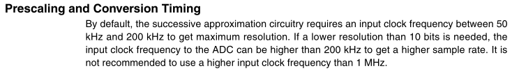
I decided to play around with using the ADC at 1MHz to get the result as fast as possible and therefore am only reading the first byte of the ADC to give us an 8 bit reading. All we do is read both pots and transmits the packet, easy.
.
Download / Improvements
Download nRF24_RC_Car_v0.1. I’ll be putting everything on the receiver into one board so I can fit the car shell cover back on.
Some features / improvements could be:
- Add headlights and tail lights on the car, selectable from the controller
- Have a battery low LED for the controller and another on the controller for the receiver’s battery
- Use the forth battery in series with the other 3 to boost the voltage on the motor to around 15.5V


I also have this radio control car LP5000QV88 model having same circuit, now it is not working correctly, i want to ask a question that, on which principle is it working, either FSK, ASK or PSK. (frequency modulation, amplitude modulation or phase modulation)?