Update 23 May 2017: There is an easier way to get Error rate in Betaflight, update your i6 transmitter with the 10Ch mod and specify Error as a channel , no soldering required – https://github.com/benb0jangles/FlySky-i6-Mod-/issues/17#issuecomment-278679083 (be aware, it will wipe your model memory)
Previously I was able to modify the Turnigy TGY-i6 transmitter to read the signal strength (RSSI) byte and illuminate an LED near the FPV display if the error rate was high so you could easily tell that it’s probably a good idea to turn around. There was a comment from Paul asking if there was a way to read the RSSI from the receiver itself and then pass this onto the flight controller or OSD. (This isn’t really RSSI but just error rate which is a good indicator when you are going to lose signal as you are too far away)
https://www.youtube.com/watch?v=uHnYfxDknrY
This sounded like a good idea so I went ahead and did just that with a spare iA6 receiver (I suspect the iA6B should be the same. Edit – it’s different, see end of post). Firstly lets do a quick teardown of the receiver.
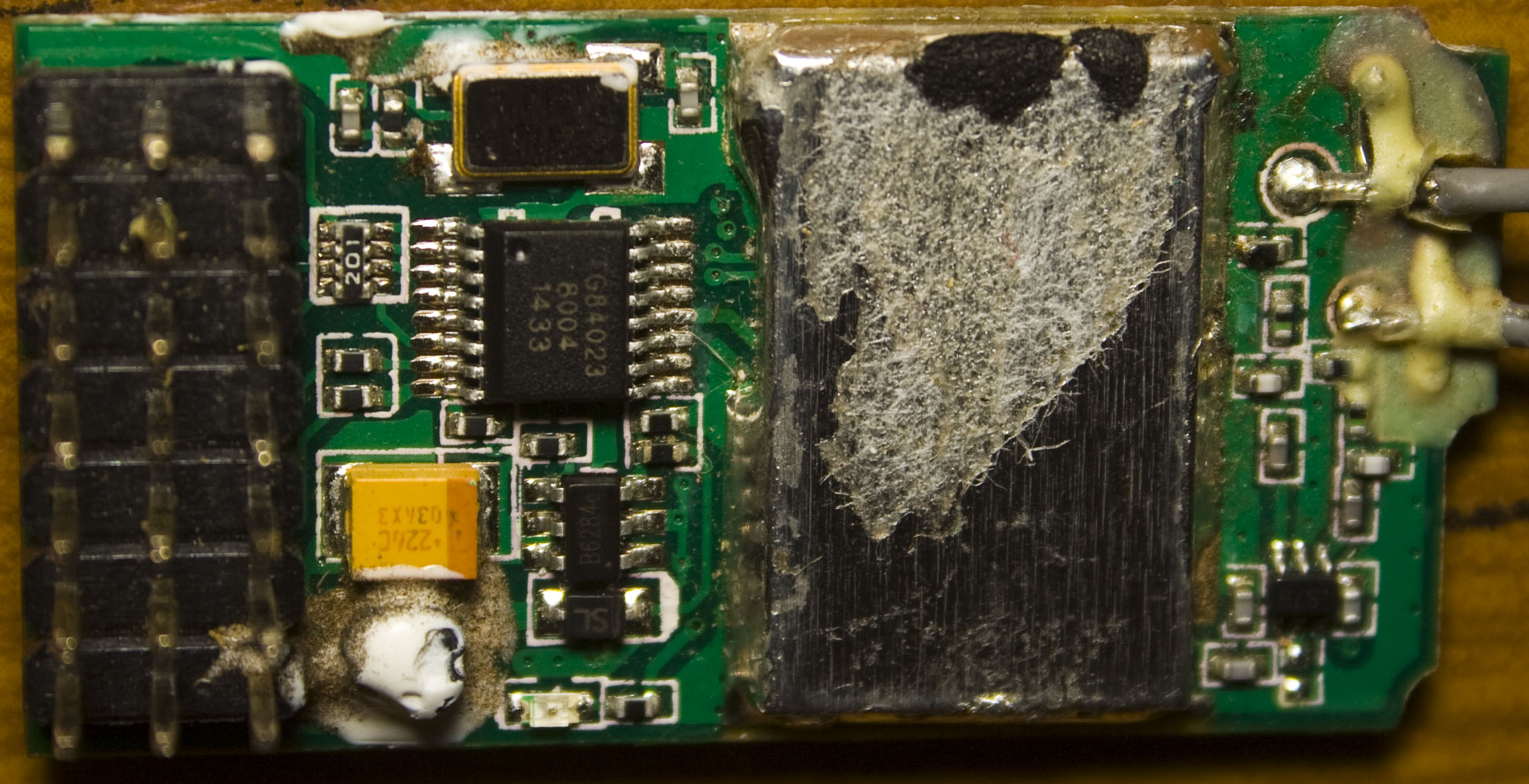
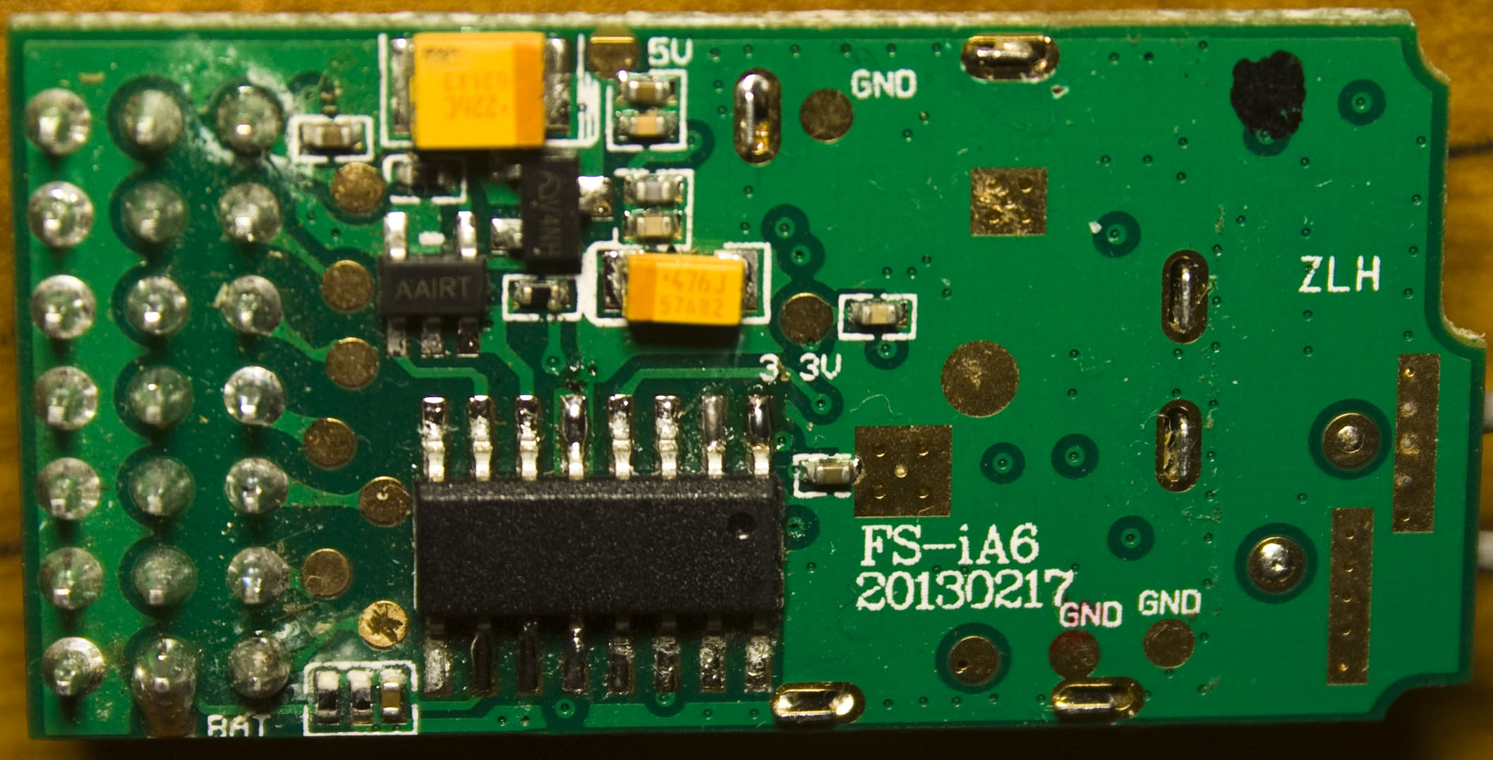
On the top we’ve got our 2 antennas going to the RF can with a microcontroller (TG84023) which would be converting the incoming data to the 6 channels, an 8MHz crystal/oscillator and on the bottom we have another MCU (no label). The PCB marking reads FS-iA6 (Flysky branded), 20130217 and it’s got 3.3V and 5V which I’ve verified so the little 3 or 6 pin packages would be an LDO for 3.3V and DC-DC boost/buck for the 5V and I think the inductor is under the white potting compound.
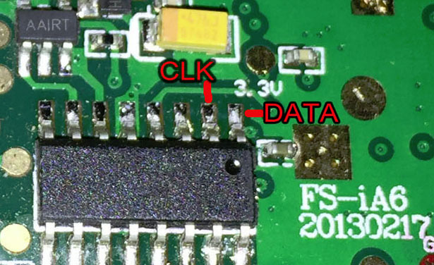
After a bit of probing around, the MCU on the bottom looked to be producing a clock output of 1MHz and some serial data. One initial problem that I thought might be an issue is with syncing the serial data to the clock pulses as at the start and near the middle there is a 4 clock block but it turns out there is an even number of them so it works out just fine.
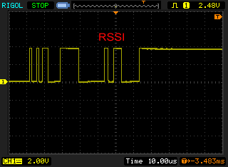
I checked near the end of the serial data and it turns out that the RSSI byte is found in the same location as on the transmitter which means we can re-use some of our existing code. At the start I wasn’t having much luck with recognising the RSSI byte but it just turns out it’s all negative clock edge instead of positive clock edge, problem solved.
// Enable USI with negative clock edge
USICR = (1<<USIWM0) | (1<<USICS1) | (1<<USICS0);

uint8_t usiResyncCounter = 0;
while(1) {
	while (!(USISR & (1<<USIOIF))); // Wait until new serial data received
	USISR |= (1<<USIOIF); // Clear received flag

	// Wait for FE and 00 sequence, then RSSI byte is next
	if (USIBR == 0xFE) {
		...
			// RSSI byte
			if (USIBR == 255) {
				rssiByte = 1; // Minimum of 1 required for shortest high period
			}
			else if (USIBR <= 84) {
				rssiByte = 255 - (USIBR * 3); // The higher error rate, the lower the RSSI signal goes
			}
		}
	}
	else if (USIBR == 0xFF) { // If receiving 8+ FFs in a row then we're near the end and can re-sync the USI to the proper clocks (if we ever started out of sync)
		usiResyncCounter++;
		if (usiResyncCounter >= 8) {
			_delay_us(500);
			USISR = (1<<USIOIF); // Clear received flag and clock counter bits
		}
	}
	else {
		usiResyncCounter = 0;
	}
}
For our MCU I went with the ATtiny25/45/85 like last time and the SMD version should be small enough to place on bottom of the PCB if you wanted to. We wait for the FE and 00 sequence of bytes (like the previous project) then capture the RSSI byte which it turns out not to give as high range of values as the transmitter did, so I timed it by 3 to give us our full range use of the byte (used for a timer compare later on).
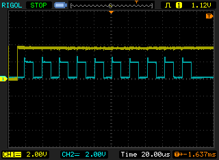
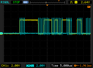
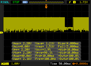
(Yellow is data when it gives us FF’s, blue is my FF checking code)
I found that near the end of the serial data there was 10-15 or so FF’s at the end and then it all goes quiet, this would be a good time to resync our serial clock just in case we ever got out of sync at start up. So we wait for 8 FF’s in a row, wait 500uS and reset the USI clock counter bits.
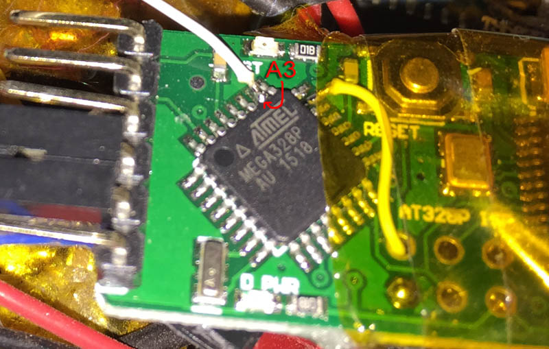
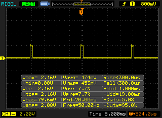
Now that we can get the RSSI byte we’ll need to feed into our flight controller or OSD, I’m going with feeding it into MinimOSD but that either requires a analog signal or a 50Hz PWM servo like signal, I’m going for the latter so what’s required is a 10-20ms delay with a 1-2ms high period. We connect to the A3 (PC3) pin on the ATmega328 to the ATtiny PB4 pin.
With the ATtiny25/45/85 we have 8 bit counters however if we used them to generate the 50Hz signal we could only have a resolution of ~13 steps per millisecond (255 / 20ms) and the OSD would only care about the 1ms high period so we could have it go up or down in 7% increments. I wanted something a bit better to give us full range so I used both timers to do this.
void setup(void) {
	...
	// Setup timers for RSSI 50Hz PWM output
	TIMSK = (1<<OCIE0A) | (1<<TOIE1) | (1<<OCIE1A);
	OCR1A = 150; // Pulse start (~100us resolution)
	OCR1C = 158; // Overflow timer for timer end and hand over to timer 0
	TCCR1 = (1<<CTC1) | (1<<PWM1A) | (1<<CS13) | (1<<CS12); // CTC

	OCR0A = 1; // Pulse end (minimum of 1), (~4us resolution)
	TCCR0A = (1<<WGM01); // CTC for 1ms
	...
}
...
// Pulse start for 1ms
ISR(TIMER1_COMPA_vect) {
	PORTB |= (1<<rssiPWMout);
}

// Turn off timer 1 and turn on timer 0 for pulse width (1ms max generation to give us 1-2ms high period)
ISR(TIMER1_OVF_vect) {
	TCCR1 = 0;

	OCR0A = rssiByte; // Update OCR0A from RSSI byte

	TCNT0 = 0;
	TCCR0B = (1<<CS01) | (1<<CS00);
}

// Turn off timer 0 and turn on timer 1 for ~50Hz PWM generation
ISR(TIMER0_COMPA_vect) {
	TCCR0B = 0;
	PORTB &= ~(1<<rssiPWMout);

	TCNT1 = 0;
	TCCR1 = (1<<CTC1) | (1<<PWM1A) | (1<<CS13) | (1<<CS12);
}
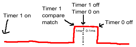
We switch on timer 1 and enable it’s overflow to generate the 50Hz signal and use the compare register to turn on the output for 1 ms (minimum pulse) right at the end so it lines up with the end of the 50Hz cycle. Once the overflow interrupt is reached, we turn off timer 1, update the compare register to be the RSSI byte for timer 0 and turn on timer 0 which has the compare match interrupt with appropriate clock to give us full range of 1 ms. Once the compare match interrupt it reached it turns off the output, turns off timer 0 and turns on timer 1 again.
It seems complex but it generates the 50Hz very well.
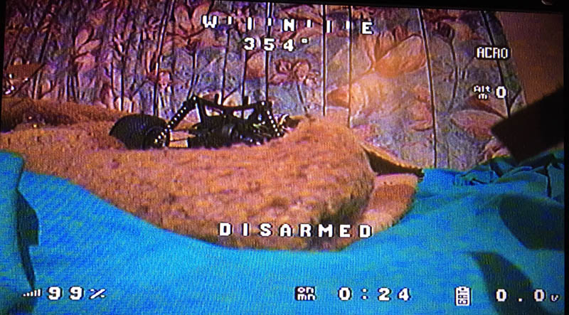
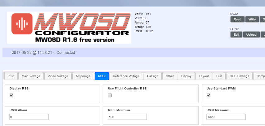
All that we need to do now is enable RSSI on MW OSD and I found that setting the RSSI Min as 126 and RSSI Max as 255 work best. And that’s it, we’re done, we now have RSSI on our OSD.
Edit: For the iA6Bv2 receiver, there is a RSSI pin which you can tap into (RCgroups). Although when I tried to tap into mine and use MWOSD to process, I could only have about 5 points of RSSI.
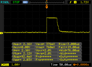
Looking at it on the scope, it looks to have a 76uS pulse when no transmitter is present and a 2.2ms pulse when it had full strength. When the signal is breaking up, the 76uS pulse shows up before the 2.2ms pulse which gets reduced to 2 ms and sometimes you can large chunks where no pulse is shown.
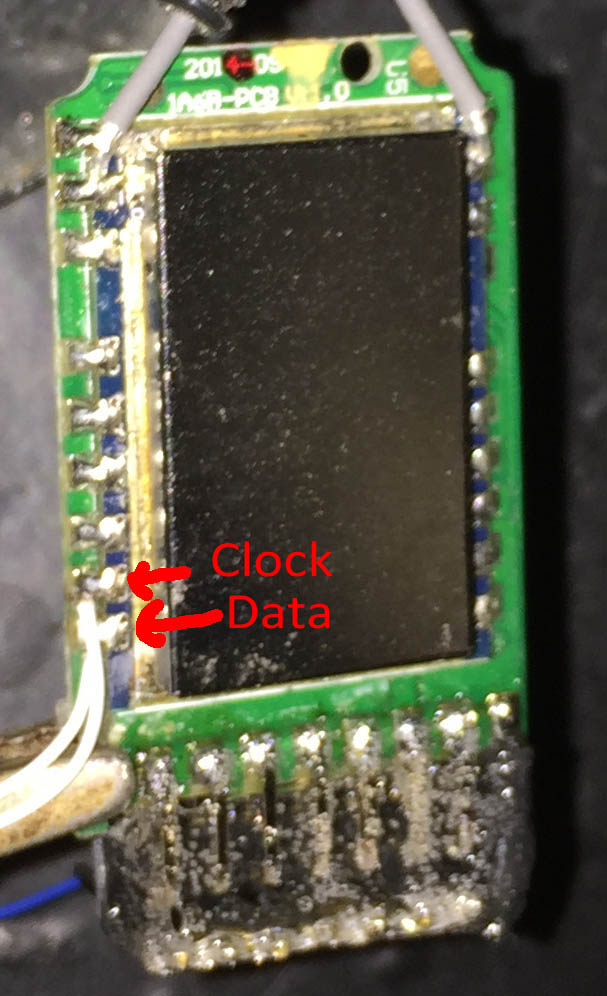
There seems to be a clock and data port on the iA6B just like the iA6 and the RF module looks exactly the same as on the TGY-i6 transmitter which we could use our same code on. I’ve tested it and it works on the iA6B though the RSSI jumps around a little bit more than the iA6 does.
Download
Download iA6_Receiver_RSSI_PWM_v1.0 (works with iA6/iA6B/iA6Bv2), recommended download for Minimosd and any other board that runs on 5V. Not suitable to hook up directly to a 3.3V flight controller unless you use a resistor divider such as 1K/2K.
If your flight controller doesn’t accept digital PWM (like an APM), we can generate an analog output at 50Hz PWM with 0% to 100% duty cycle up to 3.3V when filtered with 10K resistor and 4.7uF capacitor, you can download iA6_Receiver_RSSI_3.3V_Analog_v1.1
MWOSD R1.6 has changed the RSSI settings, please use similar settings as below:
ATtiny wiring diagram
Remember to change your fuse bits so the ATtiny85 uses 16MHz PLL and divide clock by 1
avrdude -p ATtiny85 -c usbtiny -U lfuse:w:0xe1:m -U hfuse:w:0xdf:m -U efuse:w:0xff:m
// ATtiny25/45/85 Pin map
//
//                             +-\/-+
//                 Reset PB5  1|o   |8  VCC
//                       PB3  2|    |7  PB2 iA6 Clock
//   RSSI PWM to Miniosd PB4  3|    |6  PB1
//                       GND  4|    |5  PB0 iA6 Data
//                             +----+


Hello Alex,
do you know if this work with the FlySky iA10 too ?
I try to find some Contact Data on this Page to send you a Email, but i failed.
Maybe you can mail me please ?
So i can buy one from you, if you sell a ready made one 🙂
Thank you,
Adrian
Hi Adrian,
I’m not 100% on the iA10, I haven’t been able to see any pictures of the PCB. If you have one or can find someone willing to open it up and post a picture of both sides; if the chip I connect clock/data to matches the iA6, then yes it should support it.
Alex,
I’m interested in reducing bulk and weight on my quad. Would you recommend opening the plastic case on my iA6B receiver and just putting some heat shrink around it?
Regards,
Rob
Hi Rob,
Yes I’ve done a similar thing to have it fit under my FC (I wrapped mine in kapton tape), just be careful with the little button that’s on the board, when pressed it doesn’t allow the TX to connect, not sure of it’s purpose. The case on the iA6B itself is 5 grams.
Hello Alex,
I really want to have the RSSI display on my OSD but I do not know what to with the code. I know it may seem really basic to you but could you please make a video or a tutorial on this? I think this will help a lot of people who want this function on their aircraft.
Thanks so much for your work,
Peter.
Hi Peter,
You’ll need a few things and also assuming that you will be able to solder to the iA6 receiver ok, there isn’t code that needs to be changed, you just need to flash the ATtiny fuses (as the main.c file says), compile it and program the ATtiny25 or 45 or 85 which you’ll need an AVR programmer like USBASP, some hookup wire and breadboard, all of which can be gotten from Ebay if need be and should be connected up like here – http://3.bp.blogspot.com/-q8MLBaqRpbM/UZvykr8Sh1I/AAAAAAAAAuk/BX4vFsS3DF8/s1600/tiny13isp.png
Here’s a little tutorial to help get started with Programmers Notepad – https://www.insidegadgets.com/2011/04/30/move-from-arduino-software-to-winavr-with-programmers-notepad/
Let me know how you go and if you have any additional questions.
Hey Alex,
Thanks for replying, I will let you know if this works or not soon…!
Alex,
Thanks for the great tutorial! I’m interested in getting my FS-ia6bv2 ready to output some telemetry for me for eventual use with an OSD.
Can we get more data from the ia6bv2 other than error rate/RSSI? Just curious.
For an AVR Programmer, I have the Turnigy 9xr USBASP programmer like this:
http://www.altitudehobbies.com/usbasp-avr-programming-device-for-atmel-proccessors
These are the ATTiny85 units I’m looking at on eBay:
http://www.ebay.com/sch/i.html?_from=R40&_sacat=0&_nkw=ATTiny85&LH_PrefLoc=1&rt=nc&LH_BIN=1&_trksid=p2045573.m1684
What one should I get? Do I need a new cable/wire harness to go from my USBASP to the ATTiny? If so, do you know where I can get one?
Sorry for the stupid questions, and thanks for your help.
Hi Saijin_Naib,
Yes we should be able to grab just about everything that the transmitter sends to the receiver etc, I only really checked for the control sticks values. I was thinking this could be used to re-configure things like the FPV camera’s that just use those simple button keypads like the survilzone ones so you could re-configure it in the field but I never really had the need.
The AVR programmer is fine and for the ATtiny85, you can grab the one for $2 the DIP version so you can stick it on a breadboard to program it, buy some male to male jumper cable (like http://www.ebay.com/itm/65Pcs-Male-to-Male-Solderless-Flexible-Breadboard-Jumper-Cable-Wires-For-Arduino-/252107574004) to connect the AVR Programmer’s 6 pin cable to the ATtiny and then you can cut and re-use that wire to connect it to the receiver.
Hi, if i use the pin posted on RCGroups for the iA6B reciever to recieve RSSI on my OSD, it will not work?
Sry my inglish. Hope you unnderstand.
Thanks.
Hi Facundo,
If you are just referring to that 1 pin when you open up the RF shield, it will give you a very low resolution of RSSI so I don’t recommend it.
Hello Alex,
I tried to get RSSI out of the ia6b receiver using your tutorial, but for some reason i can’t get it to work.
I got an ATtiny45. To make sure the entire process works, before flashing with your code i uploaded the sample led blink program and it in fact worked. So i changed the MCU name in Makefile to attiny45, flashed its fuses, compiled and uploaded the hex file successfuly.
The ATtiny is connected to the 2 receiver pins as on your last picture.
I got a Micro MinimOSD, its RSSI pin is connected to the PB4 on ATtiny, the osd board itself is also providing 5V power to the MCU.
Now, in the OSD itself i set the RSSI FC option to off, as we get the signal directly via the RSSI pin, and analog to off, since it’s a PWM signal. As you suggested i set the min to 126 and max to 255.
Unfortunately it doesn’t seem to work, it displays 0% RSSI no matter what. Changing the RSSI min and max values doesn’t seem to have much effect, as in the RSSI indicator displays different values, but it’s not affected by the error rate as shown on the transmitter.
I don’t have a logic analyzer so i can’t check if the ATtiny is outputting any PWM signal.
I checked every single wire 10 times, everything appears to be connected correctly.
The only thing that’s somewhat strange to me is that the receiver outputs 3.3V on the Data and Clock pins, but i assume this is normal, my knowledge here is pretty limited.
I’d welcome any suggestions.
Thanks.
Hi Jeff,
Sorry for the delay, for some reason I wasn’t notified about this message. Could you try hooking up an 220 ohm to 10K resistor and LED to the PWM output and see if it turns on at all when the receiver is on? If it doesn’t try swapping the data/clock pins around. Are you able to re-program the ATtiny45 back to the blink program ok?
The minimum logic high when running at 5V is 3V so it’s just enough to detect the 3.3V high.
Please send me an email at alex@insidegadgets.com so we can troubleshooting more.
Hello,
Any luck to get working with IA6B?
“Download iA6_Receiver_RSSI_PWM_v1.0
For an analog output at 50Hz PWM with 0% to 100% duty cycle up to 3.3V when filtered with 10K resistor and 4.7uF capacitor, you can download iA6_Receiver_RSSI_3.3V_Analog_v1.1”
I’m a little bit confused which files above are correct? And another question Attiny I connect to 5V, GND and PB4 yes?
Hi Kamil,
Both files are correct and will work with the iA6B, it just depends on your needs. Most people will just use the first file iA6_Receiver_RSSI_PWM_v1.0 for it to work with Miniosd and the like, it outputs a PWM servo like signal which most boards will accept (where the digital signal is only transmitted between a 1-2ms block, 50 times a second).
However for some boards like the APM that may require a voltage from 0V to 3.3V or similar, you can use the second download and configure the resistor/capacitor to act as a smoothing filter for the output voltage which can quickly change.
For the ATtiny, you connect the power – 5V, GND; the data and clock signal wires from the RF module to PB2 and PB0; the PB4 pin is the PWM output which you connect to Miniosd or similar or your flight controller if it supports it.
So reasuming On Attiny VCC-5V GND-GND DATA-PB2 CLOCK-PB0 PWM-PB4.
I’ve planned to connect PWM to NAZE32 pin so I use file iA6_Receiver_RSSI_PWM_v1.0.
And last the hole package must open in Atmel Studio compile and upload to Attiny correct?
BTW Great Work, i think that whole RC World is reading this topic 🙂
Hi again,
I have some problems to compile in WinAvr, could You post .hex file to upload by USBasp?
Thanks in advance
Hi Kamil,
The .hex file is included in the zip file.
Also try changing the makefile contents: (I’ll update the zip with this change shortly)
From:
# Define programs and commands.SHELL = sh
CC = /c/WinAVR-20100110/bin/avr-gcc
OBJCOPY = /c/WinAVR-20100110/bin/avr-objcopy
OBJDUMP = /c/WinAVR-20100110/bin/avr-objdump
SIZE = /c/WinAVR-20100110/bin/avr-size
AR = /c/WinAVR-20100110/bin/avr-ar rcs
NM = /c/WinAVR-20100110/bin/avr-nm
AVRDUDE = /c/WinAVR-20100110/bin/avrdude
REMOVE = rm -f
REMOVEDIR = rm -rf
COPY = cp
WINSHELL = cmd
To:
# Define programs and commands.SHELL = sh
CC = c:/WinAVR-20100110/bin/avr-gcc
OBJCOPY = c:/WinAVR-20100110/bin/avr-objcopy
OBJDUMP = c:/WinAVR-20100110/bin/avr-objdump
SIZE = c:/WinAVR-20100110/bin/avr-size
AR = c:/WinAVR-20100110/bin/avr-ar rcs
NM = c:/WinAVR-20100110/bin/avr-nm
AVRDUDE = c:/WinAVR-20100110/bin/avrdude
REMOVE = rm -f
REMOVEDIR = rm -rf
COPY = cp
WINSHELL = cmd
Hello Alex,
can i use this Attiny85? It has integrated USB, so it seems to be handy if i dont want to use an ftdi programmer, but which programmer need to be chosen then in the arduino software.
http://www.aliexpress.com/item/2016-Newest-Micro-General-USB-Development-Board-For-Arduino-USB-with-ATTiny-85-20SU/32635942473.html
Thanks for your work on this!
Brgrds
Stefan
Hi Stefan,
That would work if you were writing code in Arduino IDE and going to use it for other things in the future, the ATtiny85 acts as a USB device so no programmer needed.
However for my code, it doesn’t use the Arduino IDE, it’s code without any bootloader so you would have to re-flash the chip with a programmer such as the USBASP and connect it up to the pins.
Hi Alex,
Sorry to said that but for me this mod insn’t working. I flash attiny with 3.3 V version, connected properly via RC filter but in cleanflight I have constant 100% not changing at all. Naze32 support RSSI_ADC to 3.3V. The voltage on rssi pin is constant 3.27 but i assume the voltage is not reffer to rssi level. Unfortunately I don’t have osciloscope to check pulses. Can you help me?
Hi Kamil,
Can you try switching off the TX and see if the voltage drops off?
If that works, then it sounds like it’s connected well. Can you then try placing the transmitter either far away until you see a lot of error rate (e.g. 40-50%) or place it in a microwave which should accomplish the same then, and then see if the voltage changes?
Hi,
I need help whith RSSI on ia6 receiver, from which chip pad in receiver I need to connect the RSSI plug?
Hi Aldis,
The data pin goes to PB0 of the ATtiny (pin 5) and the clock goes to PB2 (pin 7).
Yes I used MinimOSD and connected the RSSI PWM pin PB4 (pin 3) directly to it.
The Arduino can program the ATtiny, you will firstly need to flash the Arduino as an ISP sketch first and then connect it all up like here –
http://highlowtech.org/?p=1695
Once setup, you will need to flash the hex file I provided using avrdude program, here is how to setup Programmer notepad –
https://www.insidegadgets.com/2011/04/30/move-from-arduino-software-to-winavr-with-programmers-notepad/
You will need to modify the makefile that I included to say the programmer is “Arduino”
Can you do an arduino ide version ?
Thank you Alex.
hi
do you know ic eeprom on RX ia6b ? it is eeprom 5 pin . i want to replace it on RX ia6b because it broken when crashed .
Hi, I don’t know the exact one but looking at it on the scope they aren’t using it too much at start up, so I would estimate it’s likely a 1Kbit EEPROM. Microchip seem to make the 5 pins one a fair bit, so I would order a 1Kbit and 4Kbit to test with.
Hi Alex,
I’ve downloaded your archive for analog output, put .hex file into ATtiny 25 but it doesn’t work with iA6b. I guess it is compilied for 85 chip?
Vladimir
Hi Vladimir,
You can edit the makefile and change the attiny85 to 25 and recompile, or give this hex file a go:
https://www.insidegadgets.com/wp-content/uploads/2016/11/iA6_Receiver_RSSI_PWM_v1.0_ATtiny25.zip
Hi Alex,
thanks. Have got it to work with iA6b. With transmitter in close proximity to receiver I see with oscilloscope pulses ~60 Hz with duty cycle ~50%. But it jumps from time to time to 10-20%. Is it what you mentioned as “jumps around a little bit more than the iA6 does” ? It woulkd be nice to overocome that. What can you think about RSSI averaging of 4-8 samples?
Vladimir
Hi Vladimir,
Please give this version a try, it has 4 sample averaging, haven’t tested it yet –
https://www.insidegadgets.com/wp-content/uploads/2016/11/iA6_Receiver_RSSI_PWM_Avg.zip
Hi Alex,
thanks for new version.
I’ve got some experience with assembler programming but not with C/C++. Could you say which software do you use? I’ve installed WinAvr 20100110. It has 4.3.3 compiler but your projects point to 4.8.1 compiler. It is included in Atmel Studio 6.2 but it can’t open .pnproj projects.
And one more question. Does 00 byte always follow after RSSI byte as well as in front of it? If yes it could be used to discard capturing of possible FE-00-XX sequencies in other places of bit traffic and interpreting XX as RSSI.
Hi Vladimir,
I use WinAvr and use programmers notepad which is the .pnproj file but it’s nothing special, it’s just more light weight that Atmel Studio. What I did was copy over the AVR GCC Libs from Atmel Studio over to WinAVR so that I could use the latest versions 🙂 – https://www.insidegadgets.com/2014/05/27/update-winavr-to-the-latest-avr-gcc-avrdude/
Yes I there is a 00 before and after the RSSI byte, if you have Sigrok pulseview here is the file –
https://www.insidegadgets.com/wp-content/uploads/2016/11/2015-08-23_13-57-12.zip
What about reading the error rate directly from the TX and having a buzzer there. That way, keeping your quad clean and tidy.
Hi Ryan,
Yes that would be the best solution, if the firmware was modified to do that, I just haven’t worked with STM32 parts/firmware before myself.
The lcd shows the error rate so we would just need to find where it reads that then attach an atmega with a buzzer which can just alert you at a certain percentage.
Lol. Just found the previous article which is about doing exactly what I’ve asked.
How are you able to show the rssi but not activate the buzzer when rssi drops. Could you share how you are able to modify the screen. Do you have any idea or plans to enable the buzzer and set the rssi threshold.
Hi Ryan,
I was able to tap into the communication between the RF module and the MCU and find out where the RSSI value was, this works on both the TX and RX. On the TX, if you needed a solution with the buzzer, instead of the LED I have, you could hook to the buzzer on board or have a separate one and use PWM to drive the buzzer (or grab one of those 5V buzzers that just needs power to sound). The RSSI can jump around very quickly at times, so you might hear the buzzer or see the LED blink briefly.
I did upload a version which has averaging but haven’t tested it – https://www.insidegadgets.com/2015/11/25/extracting-ia6-receiver-rssi-and-outputting-to-osd-for-fpv-display/#comment-184498
For this one to show on the FPV display, I just use Minimosd to display the RSSI signal %, you can turn it on or off via Minimosd configuration.
Hi,
Would you be able to hack x6b receiver same way?
Hi Jacob,
Possibly though the RF module looks like it might be different, the RF pins aren’t showing as they are with the iA6/B/C, would need a picture of the RF can removed to see how it looks.
Here you go:
https://darmach.ovh/screen/20170312005544.png
Thanks, it looks like they are using both the same chips as before. On the iA6B I traced the clock and data lines which go to a resistor network right next to the STM32 chip. It looks like the same resistor network and the pin mapping to the STM32 is the same on the X6B, so give these pins a go:
I ordered myself an X6B and can confirm it works as per the picture.
Edit: There appears to be an easier way – https://github.com/benb0jangles/FlySky-i6-Mod-/issues/17#issuecomment-278679083
So are your saying that we can assign the error rate on an aux channel using x6b? Will try this once i get home.
Yes you can use an aux channel but you have to update your i6 transmitter with the 10Ch mod as per the github link to make it work. Please note that it will wipe your model memory and transmitter configuration.
So I this won’t apply as I am using an i6x TX.
From what I’ve quickly read and seen, the i6x has a different MCU so this i6 software mod won’t work.
Hello dear!
i have tgy ia6c, and micro minimosd,
can i run rssi to micro minimosd?
what and how i can do it, the easy way if possible?
full noob in programming, but good at soldering
THANKS a LOT!
Hi Vladimir,
Yes you should be able to hook up the wires to the RF module like in the iA6B. You will just need to purchase the MCU with the AVR programmer.
What is the ic number of fs ia6 recevier?
I have binding issue with fsia6 recevier.
I think my ic dnt work ?please guide me?
Hi Ahmed,
Which transmitter are you trying to bind up with?
Is AFHDS2A on? (should be by default)
hi Alex,
i was setting up my receiver FS IA10B with the cc3d fc and maybe i reversed polarity or something, now it doesnt power up no led light up.
i checked the led separately and it works. i also tried to check continuity and wasn’t able to get any where. checking voltage i found most of the test pads showing .74-.76 while a couple of them show .94-.96 could you help me try to identify it or what i should be looking for or guide me to a resource where i can learn as much as being able to fix component faults.
im quite desperate right now .
thanks for helping.
centaur31@gmail.com