From the last part, we looked at how to use the Atmel ATSHA204A device for random numbers / HMAC with a private key so that the client could verify what the server sends and vice versa. Today we’ll test the client/server interaction, have the server talk to the ESP8266, add an EEPROM to keep an event log/sensor names, RTC plus I’ll briefly touch on FHSS for the Si4432.
For the client, we can stick with the ATtiny84 (or ATtiny841 which I have a few spare) and for the server I’ve gone with an ATmega168, both the client and server have an ATSHA204A device with the same private key as each other. In terms of security, it’s not the best if physical access is obtained, a client could be taken away and still have access to the system and act as a server, the best thing to do in that case would be to re-key the private key.
Client side
// Generate random number
atsha204a_command_random_number(DELAY_WDT);

// Check in
RH_RF22_resetFifos();
RH_RF22_txHeaderRequestType = CHECK_IN;
RH_RF22_send(randomNumber, 32); // Send 32 byte random number ([0] will be changed by the server)
RH_RF22_clearInterrupts(); // Must be cleared here as it goes low before the packet is sent
RH_RF22_wait_for_transmit();
RH_RF22_sleep();

// Wait for server to do nonce and HMAC
watchdog_sleep(T128MS);
watchdog_sleep(T32MS);
watchdog_sleep(T16MS);

// Wait for packet to match our address
if (wait_for_valid_packet()) {
After combining the ATSHA and Si4432 code, we can have a look at the client check in. We run the random number command function for which I’ve added the option of using _delay_ms or the watchdog timer for low power consumption. We do the usual clearing of FIFOs and interrupts, set the request type as check in and send the random number to the server.
Strangely enough if you clear the interrupts before you load the packet and turn the transmit mode on, the Si4432 will set the interrupt low straight away so it will seem like an interrupt occurred before the packet was even sent. Turns out you have to set it right after you turn the transmit mode on and it works fine. Edit: This is because we need to reset Register 06h. Interrupt Enable 2 to 0, default is 0x03 (Enable Chip Ready and Enable POR)
I’m now using Si4432 interrupts when receiving or sending a packet which allows the ATtiny to sleep during that time and wake up on a pin change however we don’t want to keep the Si4432 listening for too long. After some trial and error I found that using the watchdog to sleep for 128ms + 32ms + 16ms gives us just the right delay for the server to generate the HMAC and for us go into receive mode when its close to sending us the HMAC. I measured that it takes about 9ms after the packet is loaded for the packet to be sent (i.e enpksent is 1).
The Si4432 interrupt goes low when an interrupt occurs and we have to read the interrupt status registers to set the pin back high. When the Si4432 is put to sleep, the interrupt pin remains high, so if you had a 1M resistor pulling it to ground, that would be 3.3uA being used, so I’ve gone with no resistor.
Speaking of low current consumption, I tested the Si4432 and was getting about 1.5mA when I put it to sleep. Using the shutdown pin allowed it to jump down to a 1uA but would mean you had to re-configure it like you were powering it up for the first time. After looking around a bit I recalled that there was some GPIO ports, perhaps we need a pull up resistor on those unused pins like I know you do with AVRs.
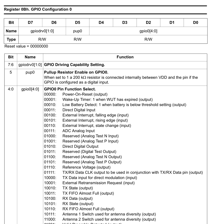
// Set GPIO 0-2 as input and pull up resistor for lower power consumption
spi_write_reg(RH_RF22_REG_0B_GPIO_CONFIGURATION0, 0x20 | 0x03);
spi_write_reg(RH_RF22_REG_0C_GPIO_CONFIGURATION1, 0x20 | 0x03);
spi_write_reg(RH_RF22_REG_0D_GPIO_CONFIGURATION2, 0x20 | 0x03);
After setting the pin as Direct Digital Input plus the internal pull up resistor of 200K, the current is now reduced to 1uA when sleeping. There are lots of other functions you could use the 3 GPIO pins for.
// Set alarm state given to us by server to our random number
randomNumber[0] = dataIn[0];

// Generate HMAC from the random number we generated and the alarm state
atsha204a_command_nonce(DELAY_WDT);
atsha204a_command_hmac(DELAY_WDT);

// Compare HMACs (31 bytes, elements 1 to 31)
uint8_t compareMatched = true;
for (uint8_t c = 1; c < 31; c++) {
	if (dataBuffer != dataIn) {
		compareMatched = false;
	}
}

// Update alarm state if compare matched
if (compareMatched == true) {
	systemStateReceived = dataIn[0];
	...
}
Back to the client, once we receive a valid packet to our address (we only listen for 32ms and wake up as soon as the packet arrives with the interrupt). The server changes the first byte of the HMAC it sends back with the system state, it also does this to the random number we sent. We replace the first byte of our random number with this byte, run nonce and HMAC. Once we have the HMAC, we compare the 31 bytes of the HMAC (1 to 31) and if it matches, we can now copy the system state (byte 0) to be the new system state and perform an action with this new state.
Server side
wait_for_valid_packet(); // Wait for packet to match our address

// Client check in
if (RH_RF22_requestType == CHECK_IN) {
	dataIn[0] = systemState; // Set state
	for (uint8_t x = 0; x < 32; x++) {
		randomNumber[x] = dataIn[x];
	}

	// Generate HMAC from random number received
	atsha204a_command_nonce(DELAY_STD); // 60 ms max wait
	atsha204a_command_hmac(DELAY_STD); // 69 ms max wait
	dataBuffer[1] = systemState; // Set state again

	// Transmit HMAC
	RH_RF22_resetFifos();
	RH_RF22_txHeaderTo = RH_RF22_fromAddress;
	RH_RF22_txHeaderRequestType = CHECK_IN_REPLY;
	RH_RF22_send(&dataBuffer[1], 32); // Starts at [1] as ignoring packet length [0]
	RH_RF22_wait_for_transmit();
For the server side, we could use interrupts too but at the moment I’m not, as the server is kept awake all the time there isn’t too much of a need. Once a valid packet arrives, we set the system state, copy the received data to the random number variable and run nonce/HMAC. Once complete, we re-set the system state in byte 1 (as the data is raw from the ATSHA, byte 0 contains the count), and then we transmit this data back to the client.
I left the server and client on for a few minutes and so far there are no problems, I’ll have to leave them on for a few days to see how it goes.
Server communication with ESP8266
I already had some dynamic content on the ESP8266 web server which allowed me on the Arduino serial port to send “S-1-Kitchen-3.5V-53-s-” and it would parse that and store it in an array, now the server just needs to send that information as well as the log, lets say the past 50 events. I’ll stick with the the default 115200 bps that the 8266 is set to.
while (USART_Receive() != 'W');
The 8266 takes a few seconds to boot and connect to the Wifi, so once it’s ready we’ll have it send a ‘W’ (for wake) so we know when it’s ready to receive serial data.
ISR(USART_RX_vect) {
	usartRxBuffer[0] = USART_Receive();
	usartRxBuffer[1] = USART_Receive();
	usartRxBuffer[2] = USART_Receive();

	// Check alarm state
	if (usartRxBuffer[0] == 'A' && usartRxBuffer[1] == '-') {
		if (usartRxBuffer[2] == '1') { // Turn on alarm
			systemState = SYSTEM_ON;
			stateChanged = true;
		}
		else if (usartRxBuffer[2] == '2') { // Turn off alarm
		...
	}
}
The server needs to be ready to accept any other commands from the 8266 such as turning the alarm on or off, so we’ll set up a USART interrupt and we expect 3 bytes in the format ‘A-1’, for example, to turn on the alarm.
// Check for post
if (server.arg(0) == "Turn On") {
  system_state = SYSTEM_ON;
  Serial.print("A-1");
}
On the 8266 side, once the Alarm on button is pressed, we read the POST data and just serial print out the command.
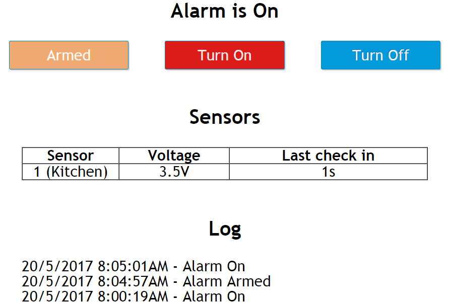
In summary, the ATmega will be sending sensor check in information, event logs and alarm triggered events to the 8266 whilst it will only send back alarm on/off/armed states.
Event log/Sensor name to EEPROM
I’m using a 128Kbit EEPROM that I had laying around which should be more than enough to store our event log/sensor names which would contain when the alarm state changed, which sensor triggered the alarm, if a sensor voltage is low, etc, I will just have it keep the last 50 events in a rotating log. The EEPROM supports page writing 64 bytes at a time so to keep it all simple each event will be 64 bytes max.
uint8_t logCounter = systemLogCount;
for (uint8_t x = 0; x < MAX_LOG; x++) {
	if (strlen(systemLog[logCounter]) >= 2) {
		temp += systemLog[logCounter];
		temp += "<br/>";
	}
	if (logCounter == 0) {
		logCounter = MAX_LOG-1;
	}
	else {
		logCounter--;
	}
}
In terms of the log rotation, we’ll have the 8266 store 50×64 bytes in an array and a variable to keep track of where the start of the log is. We read the log back to front so that the latest event is at the top and once we reach 0, we are set back to 49 (MAX_LOG-1).
// Load log current number
logCurrentNo = eeprom_read_byte((uint8_t*) logCurrentNoLocation);
...
uint8_t logCounter = logCurrentNo;
for (uint8_t x = 0; x < MAX_LOG; x++) {
	uint16_t eepromLocation = (logCounter * 64);

	// Read i2c EEPROM
	soft_i2c_eeprom_read_x_bytes(EEPROM_ADDR, eepromLocation, 64);
	if (eepromBuffer[0] != blankEeprombyte) {
		for (uint8_t e = 0; e < 64; e++) {
			if (eepromBuffer[e] != 0) {
				USART_Transmit(eepromBuffer[e]);
			}
			else {
				break;
			}
		}
		USART_Transmit(0);
	}
	else {
		break;
	}
	...
On the server side, we send all the logs after the 8266 gives us the wake command. We read the data in 64 byte chunks, if the first byte of the read is blank then we have reached the end of the event log, this will be the case when we are below 50 events. The current log number is kept in the ATmega’s internal EEPROM and is updated when an event occurs. It’s the ATmega’s job to also add this to the EEPROM and to send the new log to the 8266.
// Sensor name
soft_i2c_eeprom_read_x_bytes(EEPROM_ADDR, ((RH_RF22_fromAddress-1) * 64) + sensorNameLocation, 20);
if (eepromBuffer[0] != blankEeprombyte) {
	strncat(usartBuffer, eepromBuffer, 21);
}
else {
	strncat(usartBuffer, "Unnamed", 7);
}
strncat(usartBuffer, "-", 2);
For the sensor names, we’ll just position them in 64 byte sections too and read it out when the sensor checks in. Speaking of which I’ll need to find a way to update the sensor names, zones, etc, either program the i2c EEPROM ahead of time or have another page on the 8266 to handle this.
Real Time Clock
Of course for the events to be of any use, we need to know what day/time they happened so we’ll be using the trusty Microchip MCP7940M RTC which I’ve used a few times before and I can re-use the code too. The ATmega will be in charge of setting up the RTC, trim and updating the time if need be.
I was thinking about how we would actually use the RTC to keep track of sensors, because for log events it’s easy to read the day/time, log it and send to the 8266. However for the sensors we need to remember when they last checked in and calculate the time since that check in. The AVR libraries I’m using don’t have any time functions (but I think the new ones might) so we could convert the current time into the unix timestamp and that would make things real easy. Alternatively we could make our own unix timestamp at start it at some arbitrary date but then we need to keep track of the year, month, day and make calculations based on that.
attachInterrupt(digitalPinToInterrupt(rtcInterruptPin), uptimeUpdate, RISING);
...

void uptimeUpdate(void) {
  rtcUptime++;
}

...
// Update last seen time
sensorList[sensorNo].lastseen = rtcUptime;
But the easiest way is to use the MFP pin like done in the MiniTempLogger to output 1Hz and then increment a 32bit counter, now we can easily calculate when the sensor checked in and also tell our uptime, data/time doesn’t matter here. The ATmega doesn’t need to know the uptime so lets hook it up to an 8266 pin, enabled the interrupt and we’re done. When a sensor checks in, the 8266 just updates the check in time with the uptime.
Here’s how it’s all looking at the moment, it’s coming together. Download AlarmSM_v3.0_Test (schematic included)
Si4432 FHSS
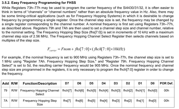
RH_RF22_setFrequency(434.0, 0.05);
RH_RF22_setModemConfig(FSK_Rb57_6Fd28_8);

spi_write_reg(RH_RF22_REG_7A_FREQUENCY_HOPPING_STEP_SIZE, 5); // Set FHSS step size as 50KHz
spi_write_reg(RH_RF22_REG_79_FREQUENCY_HOPPING_CHANNEL_SELECT, hoppingchannel); // Set channel
The Si4432 allows us to perform fast frequency switching by firstly setting our base frequency (e.g 434 MHz) and then adjusting a channel register which changes our frequency in 10KHz steps (by default), simple as that; you can change the step size from 10KHz to 2.56MHz. The step size would be determined by the modem configuration you set (28.8KHz bandwidth for me) and also the AFC pull-in (50KHz).
When testing with 10KHz steps, my receiver at 434.00 MHz would still be able to listen to packets that were sent at 434.40 MHz, it was only at 434.50 MHz that the packet wasn’t being received so we need to set our step size to 50KHz (5). If you were in the USA, you have access to the 902 – 928 MHz band, so at 50KHz per step you could cover 902 to 914.75MHz. There are various regulations to using this band, this PDF by Semtech gives a good explanation.
So how would you do FHSS if you had 50 channels you were required to switch through? I think it’s hard if the client side had to be very low power. If there wasn’t many clients, you could have each one sync up to the server which would always be switching frequencies and when the client would transmit, it could also transmit which random channel it would be on next when it woke up in x seconds. The server could reply back to the device acknowledging this, keep track of this and switch to the right frequency in time for each client.
The good news for me is I don’t need to do this as in Australia we can transmit up to 25mW on the 433MHz band for “non-specific applications”, if you did anything arbitrary that would likely be under this classification. I think I’m getting there this project, I’ll need to do more testing, find an easy way to update the date/time, sensor information and zones from the ESP8266 and finish up a few other bits and pieces such as how the server will be powered / battery backup then look at designing the server PCB; I’ve already sent the PIR/Door sensor boards out to production.


