With the LiPo battery fires I hear from time to time, I thought it might be a good idea to build a temperature monitor when charging LiPo batteries. Ideally you would put a little case over the battery with the temperature sensor inside (a low cost thermistor would do) and then if the temperature rises by approximately 15C from when you switch it on then it should alarm you.
Whether the batteries get noticeably hot when they are about to pop is something I will need to test one day (I’m sure they would to some degree) but if they do pop, I have heard that pieces can potentially go everywhere so it’s best to contain the batteries when charging.
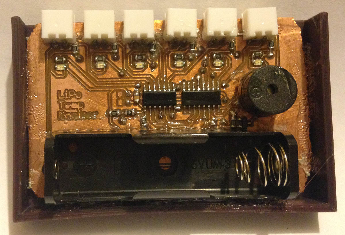
(sneak peak)
I decided to go with an ATtiny24A which would have enough pins for 6 thermistors, a buzzer, a shift register to control the LEDs and it will be powered by a LiFe 14500 battery.
Once the battery is inserted, it should read all thermistors to check if they are connected, get the base line temperature and then begin to monitor the connected thermistors. If no thermistors are connected at the start, any thermistor that was connected becomes disconnected or the temperature rises by about 15C, it should indicate which one it was and turn the buzzer on.
double thermistorTemp(int RawADC) {
  double Temp;
  Temp = log((double) ((10240000/RawADC) - 10000) / 10000); // We divide by our thermistor's resistance at 25C, in this case 10K
  Temp = 1 / (0.003354016 + (0.0002569850 * Temp) + (0.000002620131 * Temp * Temp) + (0.00000006383091 * Temp * Temp * Temp));
  Temp = Temp - 273.15; // Convert Kelvin to Celsius
  return Temp;
}
At first I thought I could get away with using the thermistorTemp function that I’ve used in the SATVL however that won’t fit in the ATtiny24A.
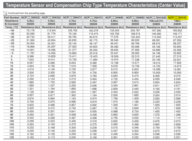
It looks like I’ll be doing this by hand which means using an array of resistance values depending on the temperature the thermistor is at. I’m using the NCPXH103 10K thermistor which gives us these values in the datasheet.
// NCPXH103 10K thermistor resistance values, from -40C to 125C in 5C steps
const float resistanceMap[34] PROGMEM = {195.652, 148.171, 113.347, 87.559, 68.237, 53.650, 42.506, 33.892, 27.219, 22.021,
	17.926, 14.674, 12.081, 10.000, 8.315, 6.948, 5.834, 4.917, 4.161, 3.535, 3.014,
	2.586, 2.228, 1.925, 1.669, 1.452, 1.268, 1.110, 0.974, 0.858, 0.758, 0.672,
	0.596, 0.531};
We’ll store it as floats using PROGMEM to save our limited SRAM space but even so it was a bit of a hassle to fit everything into the ATtiny24A 2K flash, I had to go over all the code multiple times to see what I could shave off just to make it fit.
uint8_t firstBoot = true;
uint8_t thermistorsActive = 0x3F;

while (1) {
	// Read battery voltage
	batteryVoltage = (double) adc_read(batteryAdcPin, REF_1_1V) * (double) 0.00107421875 * (double) 11;
We have a thermistors active variable, each bit represents each thermistor. As I have the thermistors connected to battery directly, the battery voltage could play a little bit into getting accurate readings rather than assuming 3.2V from our battery so we’ll need to read it with the ADC with divider resistors and 1.1V reference selected.
for (uint8_t x = 0; x < 6; x++) {
	if (firstBoot == true) { // First boot, store the starting temperatures
		int adcResult = adc_read(x, REF_VCC);
		if (adcResult <= 20) { // No thermistor connected
			thermistorsActive &= ~(1<<x);
		}
		else {
			thermStartValues[x] = resistance_to_temperature(adcResult);
		}

		shift_out(1<<(x+2));
		_delay_ms(100);

		// No thermistors active?
		if (thermistorsActive == 0) {
			shift_out(0xFF);
			PORTA |= (1<<BUZZER);
			while (1);
		}
	}
At first boot, we will read all the thermistors, if any read less than a 20 ADC value, it means that they aren’t connected as the 10K resistor would be pulling the ADC pin low, so we turn that thermistor’s bit off. Otherwise we convert the ADC result into a temperature and store that initial value. If no thermistors are connected, we sound the buzzer.
double calculateResistance(double adcResult) {
	double adcResolution = (double) batteryVoltage / (double) 1024;
	double resistanceCalc = ((double) (batteryVoltage * (double) 10) / (double) (adcResult * adcResolution)) - (double) 10;

	return resistanceCalc;
}

uint8_t resistance_to_temperature(double resistance) {
	double thermistorResistance = calculateResistance(resistance);

	// Find the closest temperature from the resistance
	for (uint8_t t = 0; t < 34; t++) {
		if (thermistorResistance >= pgm_read_float(&(resistanceMap[t]))) {
			return t;
		}
	}

	return OVER_MAX_TEMP; // Over 125C
}
To calculate the temperature, we first need to calculate the resistance of the thermistor. We have the battery voltage which will give us our ADC resolution (as we use VCC for the ADC for the thermistors), the ADC reading which would give us the voltage after the thermistor and we have to account for the 10K resistor pulling it to ground.
We take the battery voltage say 3.3V and times it by 10 for the 10K resistor to give 33. The ADC resolution would be 3.3V / 1024 = 0.00322265625 which we times our ADC result by let’s say it was 558, so 558 x 0.003222 gives us a voltage of 1.79V.
There are a few ways you could calculate the thermistor resistance, firstly by using using V = IxR, using the values we have we can do, I = 1.79V / 10K which gives 0.179 mA (179uA) that would also be flowing through the thermistor and the thermistor voltage drop would be 3.3V – 1.79V gives 1.51V. Using the formula again, R = 1.51V / 0.179mA gives 8.43K for the thermistor which is correct.
The second less complicated way is just to take the 10K out of the equation from both sides and it works too which is the way I went with: ((3.3V x 10K) / (558 x 0.003222)) – 10 = 8.43K. Another way would be ((3.3V / (558 x 0.003222)) * 10) – 10.
Now that we have the resistance we just loop through the resistance array values trying to find if our value is greater than or equal to the array value, this lets us find the closest resistance we can. The array element number gives us the temperature, it starts from -40 and goes in 5C increments so if we landed on element 13, it would be -40C + (13 x 5) = 25C. Though we don’t even need to record the temperature, we only need to record the element number as we will just check if that element number rises by 3 (5C x 3 = 15C rise).
if (thermistorsActive & (1<<x)) {
	int adcResult = adc_read(x, REF_VCC);
	shift_out(1<<(x+2));

	uint8_t currentResistance = resistance_to_temperature(adcResult);

	int tempCalc = currentResistance - thermStartValues[x];
	if (tempCalc >= 3 || adcResult <= 20 || currentResistance >= OVER_MAX_TEMP) { // Sound buzzer and light up LED
		PORTA |= (1<<BUZZER);
		while (1); // Don't do anything else until battery is removed
	}

	_delay_ms(100);
}
We can now loop for the active thermistors, check if the temperature rises by approximately 15C (worst case is it would activate at a rise of 10-20C) or if the thermistor is disconnected (say one of the wires break off) or if we are over 125C max temperature.
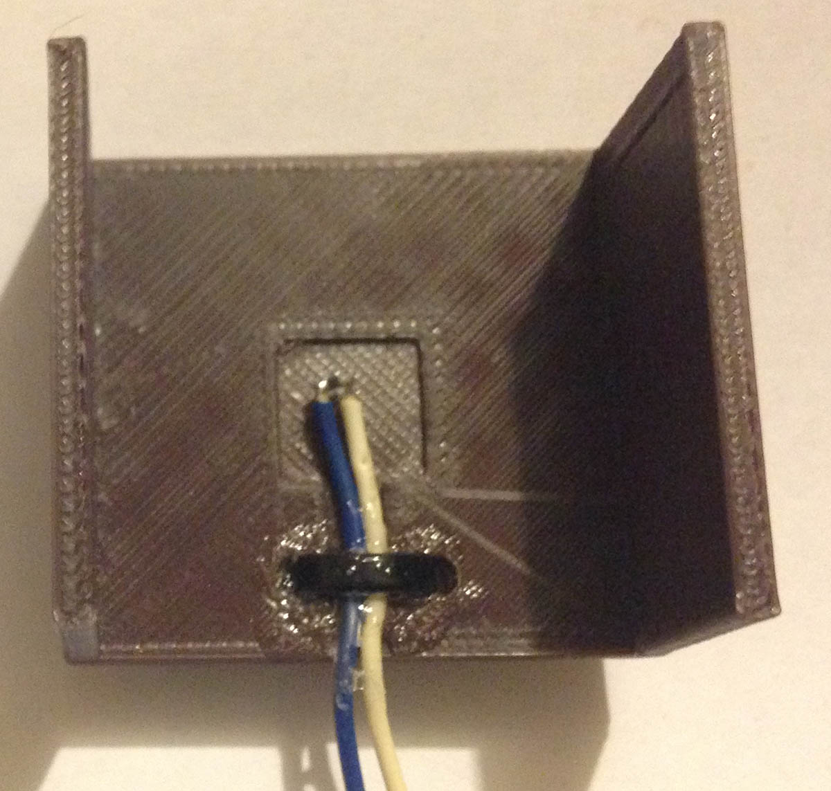
Just 3D printer a cover to wrap around the top of the battery, wire up and glue the thermistor, add in a scrolling LED animation to show which thermistor is currently been queried and we’re done.
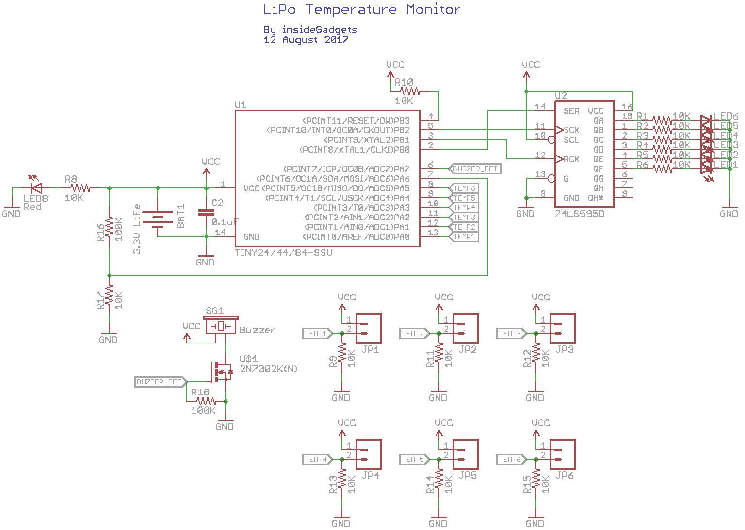
Download the Eagle schematic, board layout (for milling) and code: LiPo_Temp_Monitor_v0.1
I wonder if you didn’t have a container to store the LiPos when charging if a 3D printed case that the battery slides into would be adequate protection to contain some of it if it explodes / pops. Maybe a flexible material with some sort of force gauge could see if the battery started swelling.


